Page 3233 of 4555

TROUBLE DIAGNOSIS
ATC-55
C
D
E
F
G
H
I
K
L
MA
B
AT C
Auto Amp. Terminals and Reference ValueEJS004GS
Measure voltage between each terminal and ground by following ter-
minals and reference value for auto amp.
PIN CONNECTOR TERMINAL LAYOUT
TERMINALS AND REFERENCE VALUE FOR AUTO AMP.
RJIA2824E
RJIA0489E
Te r m i -
nal No.Wire
colorItemIgnition
switchConditionVoltage
(V)
1 BR/Y Power supply for IGN ON - Battery voltage
2 L Power supply for BAT OFF - Battery voltage
3 B Ground ON - Approx. 0
4 L/R A/C (Compressor ON) signal ONCompressor: ON Approx. 0
Compressor: OFF Approx. 5
5WPower supply for each door
motorON - Battery voltage
8 P In-vehicle sensor - - -
9 R/B Ambient sensor - - -
10 OR Sunload sensor - - -
11 B Illumination ground ON Light switch: ON Approx. 0
12 R/L Power supply for illumination ON Light switch: ON Approx. 12
15 G LAN signal ON -Approx. 5.5
17 L/YFan control amp. control sig-
nalONFan speed: 1-24th Approx. 2.5 - 3.5
Fan speed: 25th Approx. 9.0
18 R Blower motor feed back ON Fan speed: 1st Approx. 8.0
19 LG/BFan ON signal (With gasoline
engine)ONBlower fan: ON Approx. 0
Blower fan: OFF Approx. 5
HAK0652D
Page 3234 of 4555
ATC-56
TROUBLE DIAGNOSIS
20 L/W Power supply for IGN2 ON - Battery voltage
21 GY Water temperature sensor ONAt idle [after warming up,
approx. 80°C (176°F)]
CAUTION:
The waveforms vary depend-
ing on coolant temperature
22 LG/BRear window defogger ON
signalONRear window defogger: ON Approx. 0
Rear window defogger: OFF Approx. 12
23 B/WRear window defogger feed
back signalONRear window defogger: ON Approx. 12
Rear window defogger: OFF Approx. 0
24 B/Y Sensor ground ON - Approx. 0
25 BR/Y Intake sensor - - -
28 YPower supply for ambient
temperature displayON - Approx. 5
30 PU Compressor feed back signal ON-Approx. 0
When refrigerant pressure sen-
sor connector is disconnectedApprox. 5 Te r m i -
nal No.Wire
colorItemIgnition
switchConditionVoltage
(V)
SKIA0056J
Page 3235 of 4555

TROUBLE DIAGNOSIS
ATC-57
C
D
E
F
G
H
I
K
L
MA
B
AT C
Self-diagnosis FunctionEJS004GT
DESCRIPTION
The self-diagnostic system diagnoses sensors, door motors, blower motor, etc. by system line.
Self-diagnosis is step-1 to 7. There are two ways of changing method during self-diagnosis.
�Switching to self-diagnosis step-1 to 4.
Shifting from usual control to the self-diagnostic system is accomplished by starting the engine (turning
the ignition switch from OFF to ON) and pressing A/C switch for at least 5 seconds. The A/C switch must
be pressed within 10 seconds after starting the engine (ignition switch is turned ON). This system will be
canceled by either pressing intake switch or turning the ignition switch OFF. Shifting from one step to
another is accomplished be means of turning fan control dial, as required.
�Switching to self-diagnosis step-5 to 7 (Auxiliary mechanism).
Shifting from usual control to the self-diagnostic system is accomplished by starting the engine (turning
the ignition switch from OFF to ON) and pressing intake switch for at least 5 seconds. The intake switch
must be pressed within 10 seconds after starting the engine (ignition switch is turned ON). This system
will be canceled by either pressing A/C switch or turning the ignition switch OFF. Shifting from one step to
another is accomplished by means of turning fan control dial, as required.
Page 3238 of 4555
ATC-60
TROUBLE DIAGNOSIS
5. STEP-2: SENSOR CIRCUITS ARE CHECKED FOR OPEN OR SHORT CIRCUIT
1. Turn fan control dial to AUTO position.
2. Turn mode control dial to AUTO position.
CAUTION:
When switched to STEP-2, LED of REC position blinks for
approximately 25 seconds.
3. Check A/C switch LED is illuminate.
OK or NG
OK >> GO TO 6.
NG >> GO TO 9.
6. STEP-3: MODE DOOR AND INTAKE DOOR POSITIONS ARE CHECKED
1. Turn fan control dial to 1st–12th speed.
2. Check A/C switch LED is illuminate.
CAUTION:
When switched to STEP-3, LED of REC position blinks for
approximately 50 seconds.
OK or NG
OK >> GO TO 7.
NG >> GO TO 10.
7. STEP-4: OPERATION OF EACH ACTUATOR IS CHECKED
1. Turn fan control dial to 13th–25th speed.
2. Change operation status of air conditioner by changing mode control dial position.
>> GO TO 8.
SJIA0391E
SJIA0392E
Page 3240 of 4555
 at sunloa")
ATC-62
TROUBLE DIAGNOSIS
9. CHECK MALFUNCTIONING SENSOR
Refer to the following chart.
*1: Perform self-diagnosis STEP-2 under sunshine.
When performing indoors, aim a light (more than 60W) at sunload
sensor, otherwise LED of A/C switch will not indicate despite that
sunload sensor is functioning properly.
CAUTION:
When switched to STEP-2, LED of REC position blinks for
approximately 25 seconds.
*2: ATC-109, "
DIAGNOSTIC PROCEDURE FOR AMBIENT SENSOR" .
*3: AT C - 11 2 , "
DIAGNOSTIC PROCEDURE FOR IN-VEHICLE SENSOR" .
*4: AT C - 11 4 , "
DIAGNOSTIC PROCEDURE FOR SUNLOAD SENSOR" .
*5: AT C - 11 7 , "
DIAGNOSTIC PROCEDURE FOR INTAKE SENSOR" .
*6: AT C - 6 9 , "
DIAGNOSTIC PROCEDURE FOR LAN CIRCUIT" .
>> INSPECTION END
10. CHECK MALFUNCTIONING DOOR MOTOR POSITION SWITCH
Mode and/or intake door motor position switch(es) is/are malfunc-
tioning.
CAUTION:
When switched to STEP-3, LED of REC position blinks for
approximately 50 seconds.
*1: AT C - 7 5 , "
DIAGNOSTIC PROCEDURE FOR MODE DOOR
MOTOR" .
*2: AT C - 8 1 , "
DIAGNOSTIC PROCEDURE FOR INTAKE DOOR MOTOR" .
>> INSPECTION END
SJIA0393E
Mode control dial position Unusual Malfunctioning sensor (Including circuits) Reference page
VENT
A/C LED: OFFAmbient sensor *2
B/L In-vehicle sensor *3
FOOT or FOOT2
Sunload sensor
*1*4
D/F or D/F2 Intake sensor *5
DEF Air mix door motor (LCU) PBR *6
Unusual Mode or intake door position Reference page
REC LED: ON Mode door motor *1
FRE LED: ON Intake door motor *2
SJIA0394E
Page 3245 of 4555
TROUBLE DIAGNOSIS
ATC-67
C
D
E
F
G
H
I
K
L
MA
B
AT C
Power Supply and Ground Circuit for Auto Amp.EJS004GV
SYMPTOM: A/C system does not come on.
INSPECTION FLOW
COMPONENT DESCRIPTION
Auto Amp. (Automatic Amplifier)
The auto amp. has a built-in microcomputer which processes infor-
mation sent from various sensors needed for air conditioner opera-
tion. The air mix door motor, mode door motor, intake door motor,
blower motor and compressor are then controlled.
The auto amp. is unitized with control mechanisms. Signals from
various switches and Potentio Temperature Control (PTC) are
directly entered into auto amp.
Self-diagnostic functions are also built into auto amp. to provide
quick check of malfunctions in the auto air conditioner system.
*1AT C - 6 5 , "Operational Check".*2ATC-68, "DIAGNOSTIC PROCE-
DURE FOR A/C SYSTEM".
RJIA2826E
RJIA2824E
Page 3251 of 4555
TROUBLE DIAGNOSIS
ATC-73
C
D
E
F
G
H
I
K
L
MA
B
AT C
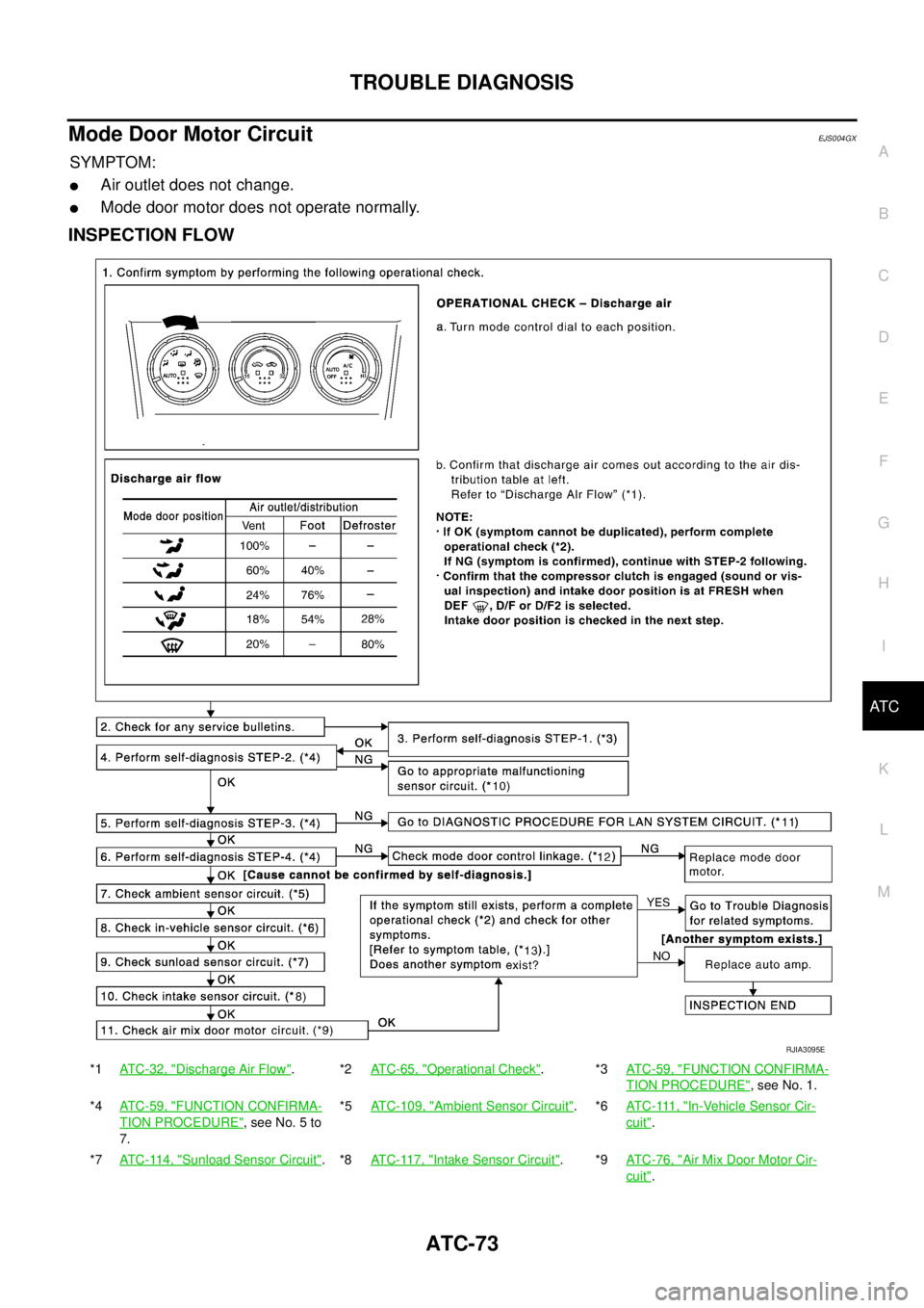
Mode Door Motor CircuitEJS004GX
SYMPTOM:
�Air outlet does not change.
�Mode door motor does not operate normally.
INSPECTION FLOW
*1ATC-32, "Discharge Air Flow".*2ATC-65, "Operational Check".*3ATC-59, "FUNCTION CONFIRMA-
TION PROCEDURE", see No. 1.
*4ATC-59, "
FUNCTION CONFIRMA-
TION PROCEDURE", see No. 5 to
7.*5ATC-109, "
Ambient Sensor Circuit".*6AT C - 111 , "In-Vehicle Sensor Cir-
cuit".
*7ATC-114, "
Sunload Sensor Circuit".*8ATC-117, "Intake Sensor Circuit".*9ATC-76, "Air Mix Door Motor Cir-
cuit".
RJIA3095E
Page 3252 of 4555

�A/C LAN system (PBR built-in air mix door motor, mode door mot")
ATC-74
TROUBLE DIAGNOSIS
SYSTEM DESCRIPTION
Component Parts
Mode door control system components are:
�Auto amp.
�Mode door motor (LCU)
�A/C LAN system (PBR built-in air mix door motor, mode door motor and intake door motor)
�In-vehicle sensor
�Ambient sensor
�Sunload sensor
�Intake sensor
System Operation
The auto amp. receives data from each of the sensors. The auto amp. sends air mix door, mode door and
intake door opening angle data to the air mix door motor LCU, mode door motor LCU and intake door motor
LCU.
The air mix door motor, mode door motor and intake door motor read their respective signals according to the
address signal. Opening angle indication signals received from the auto amp. and each of the motor position
sensors are compared by the LCUs in each motor with the existing decision and opening angles. Subse-
quently, HOT/COLD or DEF/VENT or FRESH/RECIRCULATION operation is selected. The new selection
data is returned to the auto amp.
Mode Door Control Specification
*10ATC-59, "FUNCTION CONFIRMA-
TION PROCEDURE", see No. 9.*11AT C - 6 9 , "
LAN System Circuit".*12ATC-134, "MODE DOOR MOTOR".
*13ATC-34, "
SYMPTOM TABLE".
RJIA2828E
RHA384HA
![NISSAN X-TRAIL 2005 Service Repair Manual ATC-56
TROUBLE DIAGNOSIS
20 L/W Power supply for IGN2 ON - Battery voltage
21 GY Water temperature sensor ONAt idle [after warming up,
approx. 80°C (176°F)]
CAUTION:
The waveforms vary depend-
in](/manual-img/5/57403/w960_57403-3233.png "NISSAN X-TRAIL 2005 Service Repair Manual ATC-56
TROUBLE DIAGNOSIS
20 L/W Power supply for IGN2 ON - Battery voltage
21 GY Water temperature sensor ONAt idle [after warming up,
approx. 80°C (176°F)]
CAUTION:
The waveforms vary depend-
in")