Page 3254 of 4555
ATC-76
TROUBLE DIAGNOSIS
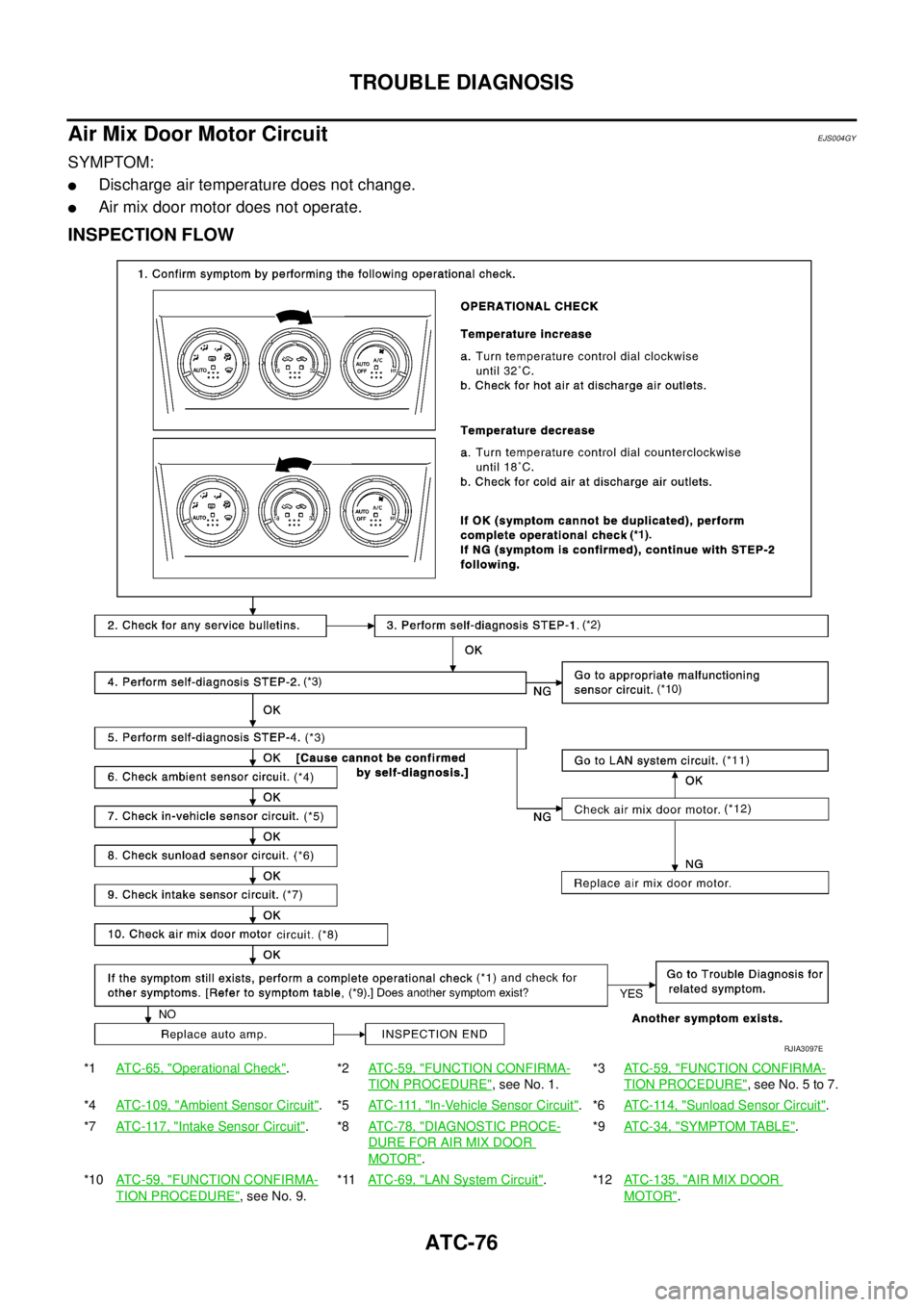
Air Mix Door Motor CircuitEJS004GY
SYMPTOM:
�Discharge air temperature does not change.
�Air mix door motor does not operate.
INSPECTION FLOW
*1AT C - 6 5 , "Operational Check".*2AT C - 5 9 , "FUNCTION CONFIRMA-
TION PROCEDURE", see No. 1.*3ATC-59, "
FUNCTION CONFIRMA-
TION PROCEDURE", see No. 5 to 7.
*4ATC-109, "
Ambient Sensor Circuit".*5AT C - 111 , "In-Vehicle Sensor Circuit".*6ATC-114, "Sunload Sensor Circuit".
*7AT C - 11 7 , "
Intake Sensor Circuit".*8AT C - 7 8 , "DIAGNOSTIC PROCE-
DURE FOR AIR MIX DOOR
MOTOR".*9ATC-34, "
SYMPTOM TABLE".
*10AT C - 5 9 , "
FUNCTION CONFIRMA-
TION PROCEDURE", see No. 9.*11AT C - 6 9 , "
LAN System Circuit".*12ATC-135, "AIR MIX DOOR
MOTOR".
RJIA3097E
Page 3255 of 4555

�A/C LAN system (PBR built-in")
TROUBLE DIAGNOSIS
ATC-77
C
D
E
F
G
H
I
K
L
MA
B
AT C
SYSTEM DESCRIPTION
Component Parts
Air mix door control system components are:
�Auto amp.
�Air mix door motor (LCU)
�A/C LAN system (PBR built-in air mix door motor, mode door motor and intake door motor)
�In-vehicle sensor
�Ambient sensor
�Sunload sensor
�Intake sensor
System Operation
The auto amp. receives data from each of the sensors. The auto amp sends air mix door, mode door and
intake door opening angle data to the air mix door motor LCU, mode door motor LCU and intake door motor
LCU.
The air mix door motor, mode door motor and intake door motor read their respective signals according to the
address signal. Opening angle indication signals received from the auto amp. and each of the motor position
sensors are compared by the LCUs in each motor with the existing decision and opening angles. Subse-
quently, HOT/COLD or DEF/VENT or FRESH/RECIRCULATION operation is selected. The new selection
data is returned to the auto amp.
Air Mix Door Control Specification
RHA424GB
RHA457H
Page 3257 of 4555
TROUBLE DIAGNOSIS
ATC-79
C
D
E
F
G
H
I
K
L
MA
B
AT C
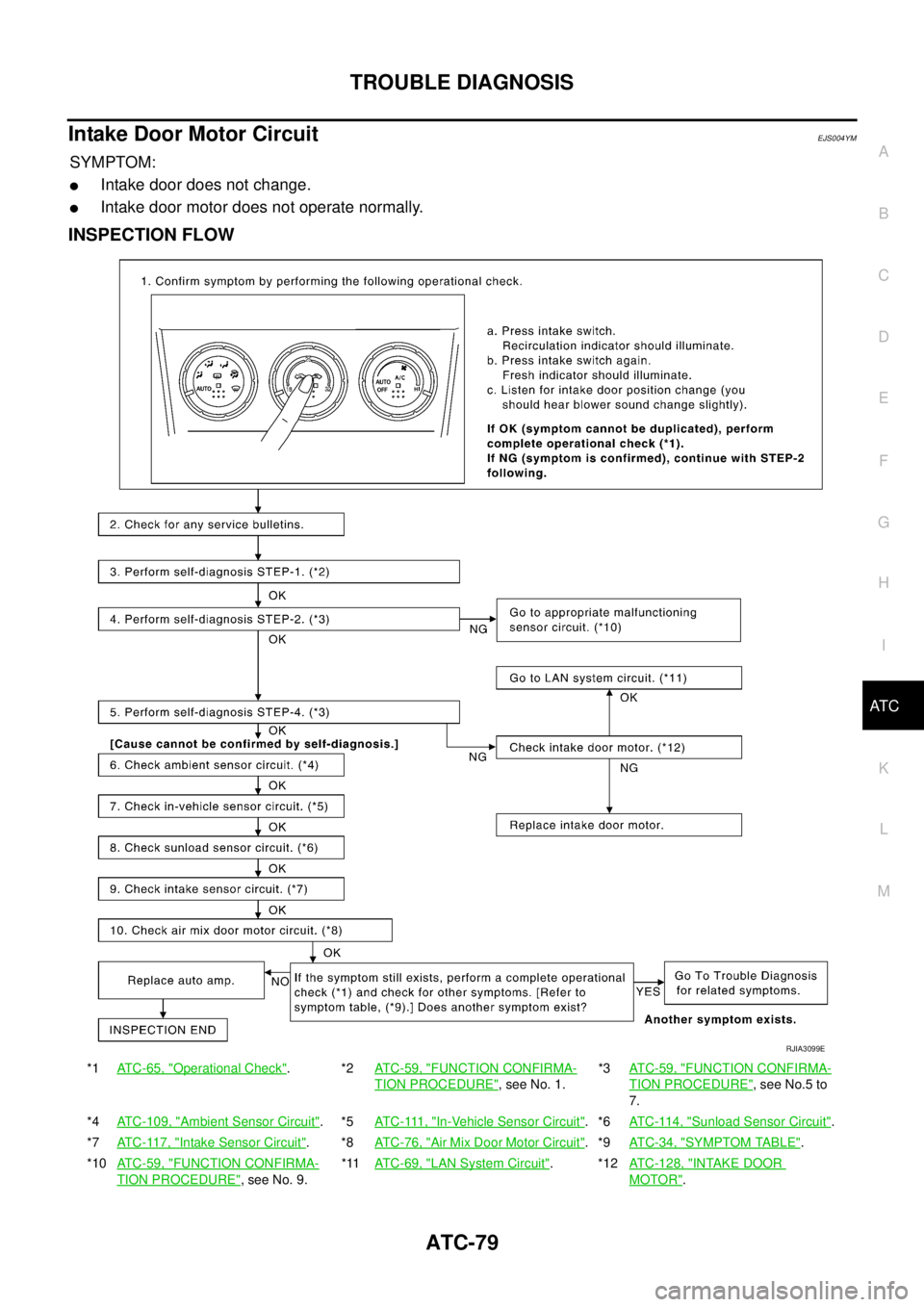
Intake Door Motor CircuitEJS004YM
SYMPTOM:
�Intake door does not change.
�Intake door motor does not operate normally.
INSPECTION FLOW
*1ATC-65, "Operational Check".*2ATC-59, "FUNCTION CONFIRMA-
TION PROCEDURE", see No. 1.*3AT C - 5 9 , "
FUNCTION CONFIRMA-
TION PROCEDURE", see No.5 to
7.
*4ATC-109, "
Ambient Sensor Circuit".*5AT C - 111 , "In-Vehicle Sensor Circuit".*6AT C - 11 4 , "Sunload Sensor Circuit".
*7ATC-117, "
Intake Sensor Circuit".*8ATC-76, "Air Mix Door Motor Circuit".*9AT C - 3 4 , "SYMPTOM TABLE".
*10ATC-59, "
FUNCTION CONFIRMA-
TION PROCEDURE", see No. 9.*11ATC-69, "
LAN System Circuit".*12ATC-128, "INTAKE DOOR
MOTOR".
RJIA3099E
Page 3258 of 4555
ATC-80
TROUBLE DIAGNOSIS
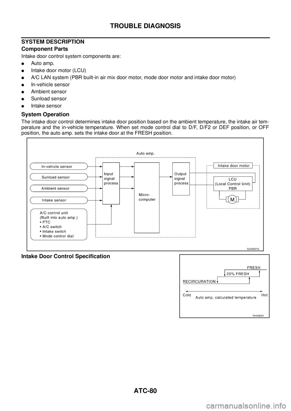
SYSTEM DESCRIPTION
Component Parts
Intake door control system components are:
�Auto amp.
�Intake door motor (LCU)
�A/C LAN system (PBR built-in air mix door motor, mode door motor and intake door motor)
�In-vehicle sensor
�Ambient sensor
�Sunload sensor
�Intake sensor
System Operation
The intake door control determines intake door position based on the ambient temperature, the intake air tem-
perature and the in-vehicle temperature. When set mode control dial to D/F, D/F2 or DEF position, or OFF
position, the auto amp. sets the intake door at the FRESH position.
Intake Door Control Specification
RJIA2831E
RHA383H
Page 3260 of 4555
ATC-82
TROUBLE DIAGNOSIS
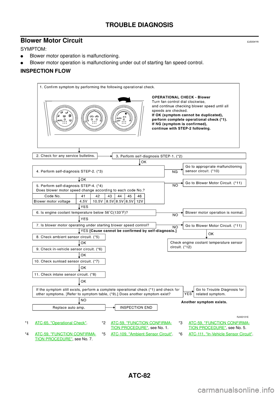
Blower Motor CircuitEJS004YN
SYMPTOM:
�Blower motor operation is malfunctioning.
�Blower motor operation is malfunctioning under out of starting fan speed control.
INSPECTION FLOW
*1ATC-65, "Operational Check".*2ATC-59, "FUNCTION CONFIRMA-
TION PROCEDURE", see No. 1.*3ATC-59, "
FUNCTION CONFIRMA-
TION PROCEDURE", see No. 5.
*4ATC-59, "
FUNCTION CONFIRMA-
TION PROCEDURE", see No. 7.*5ATC-109, "
Ambient Sensor Circuit".*6AT C - 111 , "In-Vehicle Sensor Circuit".
RJIA3101E
Page 3261 of 4555

TROUBLE DIAGNOSIS
ATC-83
C
D
E
F
G
H
I
K
L
MA
B
AT C
SYSTEM DESCRIPTION
Component Parts
Fan speed control system components are:
�Auto amp.
�A/C LAN system (PBR built-in air mix door motor, mode door motor and intake door motor)
�Fan control amp.
�In-vehicle sensor
�Ambient sensor
�Sunload sensor
�Intake sensor
System Operation
Automatic Mode
In the automatic mode, the blower motor speed is calculated by the auto amp. based on input from the PBR,
in-vehicle sensor, sunload sensor, intake sensor and ambient sensor.
The blower motor applied voltage ranges from approximately 4 volts (lowest speed) to 12 volts (highest
speed).
The control blower speed (in the range of 4 to 12V), the auto amp. supplies a gate voltage to the fan control
amp. Based on this voltage, the fan control amp. controls the voltage supplied to the blower motor.
*7AT C - 11 4 , "Sunload Sensor Circuit".*8ATC-117, "Intake Sensor Circuit".*9AT C - 3 4 , "SYMPTOM TABLE".
*10AT C - 5 9 , "
FUNCTION CONFIRMA-
TION PROCEDURE", see No. 9.*11ATC-84, "
DIAGNOSTIC PROCE-
DURE FOR BLOWER MOTOR".*12 QR engine; (WITH EURO-OBD) EC-165, "DTC P0117, P0118 ECT SEN-
SOR" .
QR engine; (WITHOUT EURO-OBD)
EC-652, "
DTC P0117, P0118 ECT
SENSOR" .
YD engine; (WITH EURO-OBD) EC-
1093, "DTC P0117, P0118 ECT
SENSOR" .
YD engine; (WITHOUT EURO-OBD)
EC-1449, "
DTC P0117, P0118 ECT
SENSOR" .
RJIA2833E
Page 3266 of 4555
ATC-88
TROUBLE DIAGNOSIS
Magnet Clutch CircuitEJS004YO
SYMPTOM: Magnet clutch does not engage.
INSPECTION FLOW
*1AT C - 6 5 , "Operational Check".*2ATC-59, "FUNCTION CONFIRMA-
TION PROCEDURE", see No. 1.*3ATC-59, "
FUNCTION CONFIRMA-
TION PROCEDURE", see No. 5 to
7.
*4ATC-109, "
Ambient Sensor Circuit".*5ATC-117, "Intake Sensor Circuit".*6ATC-34, "SYMPTOM TABLE".
*7AT C - 5 9 , "
FUNCTION CONFIRMA-
TION PROCEDURE", see No. 9.*8ATC-89, "
DIAGNOSTIC PROCE-
DURE FOR MAGNET CLUTCH".*9ATC-102, "
TROUBLE DIAGNOSIS
FOR UNUSUAL PRESSURE".
RJIA3103E
Page 3267 of 4555
TROUBLE DIAGNOSIS
ATC-89
C
D
E
F
G
H
I
K
L
MA
B
AT C
SYSTEM DESCRIPTION
Auto amp. controls compressor operation by ambient temperature, intake air temperature (with diesel engine)
and signal from ECM.
Low Temperature Protection Control (With Gasoline Engine)
Auto amp. will turn compressor ON or OFF as determined by a sig-
nal detected by ambient sensor.
When ambient temperatures are higher than −2°C (28°F), compres-
sor turns ON. Compressor turns OFF when ambient temperatures
are lower than −5°C (23°F).
Evaporator Freeze Protection Control (With Diesel Engine)
Auto amp. will turn compressor ON or OFF as determined by a sig-
nal detected by intake sensor.
When intake air temperatures are higher than 4°C (39°F), compres-
sor turns ON. Compressor turns OFF when intake temperatures are
lower than 2.5°C (37°F).
DIAGNOSTIC PROCEDURE FOR MAGNET CLUTCH
SYMPTOM: Magnet clutch does not engage when A/C switch is ON.
RHA094GB
RHA094GD
RJIA2835E


and signal from EC")