Page 3157 of 4555
![NISSAN X-TRAIL 2005 Service Repair Manual TROUBLE DIAGNOSIS
BRC-109
[ESP/TCS/ABS]
C
D
E
G
H
I
J
K
L
MA
B
BRC
Inspection 15 CAN Communication Circuit, ESP/TCS/ABS Control Unit and
Steering Angle Sensor
EFS005WK
INSPECTION PROCEDURE
1. CHECK](/manual-img/5/57403/w960_57403-3156.png "NISSAN X-TRAIL 2005 Service Repair Manual TROUBLE DIAGNOSIS
BRC-109
[ESP/TCS/ABS]
C
D
E
G
H
I
J
K
L
MA
B
BRC
Inspection 15 CAN Communication Circuit, ESP/TCS/ABS Control Unit and
Steering Angle Sensor
EFS005WK
INSPECTION PROCEDURE
1. CHECK")
TROUBLE DIAGNOSIS
BRC-109
[ESP/TCS/ABS]
C
D
E
G
H
I
J
K
L
MA
B
BRC
Inspection 15 CAN Communication Circuit, ESP/TCS/ABS Control Unit and
Steering Angle Sensor
EFS005WK
INSPECTION PROCEDURE
1. CHECK CONNECTOR
1. Turn ignition switch OFF, disconnect the ESP/TCS/ABS control unit connector, and check the terminal for
deformation, disconnection, looseness, and so on. If there is a malfunction, repair or replace the terminal.
2. Reconnect connector to perform self-diagnosis.
Is
“CAN COMM CIRCUIT” or “ST ANG SEN COM CIR” displayed in the self-diagnosis display items?
YES >> Print out the self-diagnostic results, and refer to BRC-56, "CAN COMMUNICATION" .
NO >> Connector terminal connection is loose, damaged, open, or shorted.
Component CheckEFS005WL
ESP OFF SWITCH
�Disconnect the ESP OFF switch connector. Check for continuity
between the terminal No. 1 and No. 2.
ESP RELAY BOX
Disconnect the relay box connectors. Check for continuity, resis-
tance value, and insulation between any pair of terminals in the relay
box. 1 - 2 : Pressing the switch will make a continu-
ity, and releasing it will stop the continuity.
SFIA1822E
SFIA1823E
Page 3160 of 4555
![NISSAN X-TRAIL 2005 Service Repair Manual BRC-112
[ESP/TCS/ABS]
TROUBLE DIAGNOSIS
Actuator operation check
1. Connect 9 and 10 terminals of actuator to 40 and 41 terminals of
relay box.
2. Measure the motor voltage (No.4 terminal to body ea](/manual-img/5/57403/w960_57403-3159.png "NISSAN X-TRAIL 2005 Service Repair Manual BRC-112
[ESP/TCS/ABS]
TROUBLE DIAGNOSIS
Actuator operation check
1. Connect 9 and 10 terminals of actuator to 40 and 41 terminals of
relay box.
2. Measure the motor voltage (No.4 terminal to body ea")
BRC-112
[ESP/TCS/ABS]
TROUBLE DIAGNOSIS
Actuator operation check
1. Connect 9 and 10 terminals of actuator to 40 and 41 terminals of
relay box.
2. Measure the motor voltage (No.4 terminal to body earth) with
oscilloscope. Then check the motor reverse voltage occasioned
time.
The motor reverse voltage occasioned time is more than 0.1
sec.
CAUTION:
�Perform checking of motor relay unit. Then confirm that
relay functions.
�Driving actuator motor is with in 4 sec. to prevent heating
up.
�Standard condition of the motor reverse voltage occa-
sioned time is: Battery voltage is 12V. Temperature 20°.
when the battery voltage or temperature is lower than the
standard, the motor reverse voltage occasioned time
becomes slightly shorter.
Symptom 1: ABS Works FrequentlyEFS005WM
1. CHECK START
Check longitudinal brake force distribution using a brake tester.
OK or NG
OK >> GO TO 2.
NG >> Check brake system.
2. CHECK FRONT AND REAR AXLE
Check to make sure that there is no excessive play in the front and rear axles. Refer to Front: FAX-7, "
On-
Vehicle Inspection" , Rear: RAX-6, "WHEEL BEARING INSPECTION" (2WD), RAX-10, "REAR WHEEL
BEARING" (4WD).
OK or NG
OK >> GO TO 3.
NG >> Repair.
3. CHECK WHEEL SENSOR AND SENSOR ROTOR
Check wheel sensor and sensor rotor for the following.
�Sensor installation for damage
�Sensor rotor installation for damage
�Sensor connector engagement
�Sensor harness
OK or NG
OK >> GO TO 4.
NG >>
�Replace wheel sensor or sensor rotor.
�Repair harness.
SFIA1824E
Page 3161 of 4555
![NISSAN X-TRAIL 2005 Service Repair Manual TROUBLE DIAGNOSIS
BRC-113
[ESP/TCS/ABS]
C
D
E
G
H
I
J
K
L
MA
B
BRC
4. CHECK ABS WARNING LAMP DISPLAY
Make sure that the warning lamp turns off approximately 2 second after the key switch is turned o](/manual-img/5/57403/w960_57403-3160.png "NISSAN X-TRAIL 2005 Service Repair Manual TROUBLE DIAGNOSIS
BRC-113
[ESP/TCS/ABS]
C
D
E
G
H
I
J
K
L
MA
B
BRC
4. CHECK ABS WARNING LAMP DISPLAY
Make sure that the warning lamp turns off approximately 2 second after the key switch is turned o")
TROUBLE DIAGNOSIS
BRC-113
[ESP/TCS/ABS]
C
D
E
G
H
I
J
K
L
MA
B
BRC
4. CHECK ABS WARNING LAMP DISPLAY
Make sure that the warning lamp turns off approximately 2 second after the key switch is turned on or when
driving.
OK or NG
OK >> Normal
NG >> Perform self-diagnosis. Refer to BRC-81, "
SELF-DIAGNOSIS" .
Symptom 2: Unexpected Pedal ReactionEFS005WN
1. CHECK BRAKE PEDAL STROKE
Check brake pedal stroke. Refer to BR-6, "
On-Vehicle Inspection and Adjustment" .
Is the stroke too large?
YES >>�Bleed air from the brake piping. Refer to BR-9, "Bleeding Brake System" .
�Check brake pedal, brake booster, and master cylinder for mount play, looseness, brake sys-
tem fluid leakage, etc. Repair if necessary. Refer to Brake pedal: BR-6, "
BRAKE PEDAL" ,
brake booster and master cylinder: BR-23, "
BRAKE BOOSTER" .
NO >> GO TO 2.
2. PERFORMANCE CHECK
Disconnect ESP/TCS/ABS control unit connector to deactivate ABS. Check if braking force is normal in this
condition. Connect connector after inspection.
OK or NG
OK >> GO TO 3. Wheel Sensor Inspection in Refer to BRC-91, "Inspection 1 Wheel Sensor System" .
NG >> Check brake system.
Symptom 3: Longer Stopping DistanceEFS005WO
CAUTION:
The stopping distance on slippery road surfaces might be longer with the ABS operating than when
the ABS is not operating.
1. PERFORMANCE CHECK
Turn ignition switch OFF. Disconnect ESP/TCS/ABS control unit connector to deactivate ABS. In this condi-
tion, check stopping distance. After inspection, connect connector.
OK or NG
OK >> GO TO BRC-112, "Symptom 1: ABS Works Frequently" .
NG >>
�Bleed air from the brake piping. Refer to BR-9, "Bleeding Brake System" .
�Check brake system.
Symptom 4: ABS Does Not WorkEFS005WP
CAUTION:
ABS does not operate when speed is 10 km/h or lower.
1. CHECK ABS WARNING LAMP DISPLAY
Make sure that the warning lamp turns off approximately 2 second after the key switch is turned on or when
driving.
OK or NG
OK >> GO TO 3. Check wheel sensor and sensor rotor in Refer to BRC-91, "Inspection 1 Wheel Sensor
System" .
NG >> Perform self-diagnosis. Refer to BRC-81, "
SELF-DIAGNOSIS" .
Symptom 5: Pedal Vibration and ABS Operation NoiseEFS005WQ
CAUTION:
Under the following conditions, ABS is activated and vibration is felt when brake pedal is lightly
depressed (just place a foot on it). However, this is normal.
Page 3162 of 4555
![NISSAN X-TRAIL 2005 Service Repair Manual BRC-114
[ESP/TCS/ABS]
TROUBLE DIAGNOSIS
�When shifting gears
�When driving on slippery road
�During cornering at high speed
�When passing over bumps or grooves (Approx. 50 mm or more)
�When pulling](/manual-img/5/57403/w960_57403-3161.png "NISSAN X-TRAIL 2005 Service Repair Manual BRC-114
[ESP/TCS/ABS]
TROUBLE DIAGNOSIS
�When shifting gears
�When driving on slippery road
�During cornering at high speed
�When passing over bumps or grooves (Approx. 50 mm or more)
�When pulling")
BRC-114
[ESP/TCS/ABS]
TROUBLE DIAGNOSIS
�When shifting gears
�When driving on slippery road
�During cornering at high speed
�When passing over bumps or grooves (Approx. 50 mm or more)
�When pulling away just after starting engine (Approx. 10 km/h or more)
1. SYMPTOM CHECK 1
Check if pedal vibration or operation sounds occur when the engine is started.
OK or NG
OK >> GO TO 2.
NG >> Perform self-diagnosis. Refer to BRC-81, "
SELF-DIAGNOSIS" .
2. SYMPTOM CHECK 2
Check symptoms when electrical component (headlamps, etc.) Switches are operated.
Do symptoms occur?
YES >> Check if there is a radio, antenna, antenna lead wire, or wiring close to the control unit. If there is,
move it farther away.
NG >> GO TO 3. Check wheel sensor and sensor rotor in Refer to BRC-91, "
Inspection 1 Wheel Sensor
System" .
Symptom 6: ESP OFF Indicator Lamp Does Not IlluminateEFS005WR
INSPECTION PROCEDURE
1. ESP OFF INDICATOR LAMP INSPECTION
Disconnect ESP/TCS/ABS control unit connector.
Does ABS warning lamp and ESP OFF indicator lamp illuminate?
YES >> ESP/TCS/ABS control unit malfunction. Repair or replace the control unit.
NO >> Combination meter system malfunction. Check the combination meter.
Symptom 7: SLIP Indicator Lamp Does Not IlluminateEFS005WS
INSPECTION PROCEDURE
1. SLIP INDICATOR LAMP CONNECTOR INSPECTION
Check connectors for ESP/TCS/ABS control unit and meter vehicle-side harness.
Is inspection result OK?
YES >> GO TO 2.
NO >> Repair or replace the disconnected connector.
2. SLIP INDICATOR LAMP POWER CIRCUIT INSPECTION
Disconnect the meter connector. Check that the voltage between the
vehicle-side harness terminal and body ground is battery voltage
(Approx. 12V).
Is inspection result OK?
YES >> GO TO Refer to BRC-109, "Inspection 15 CAN Commu-
nication Circuit, ESP/TCS/ABS Control Unit and Steer-
ing Angle Sensor" .
NO >>
�Fuse inspection
�Inspection for harness and connectors between fuse
block and meter
�Check the power supply circuit (battery and ignition
switch circuit).SFIA2207E
Page 3164 of 4555
![NISSAN X-TRAIL 2005 Service Repair Manual BRC-116
[ESP/TCS/ABS]
WHEEL SENSORS
WHEEL SENSORSPFP:47910
Removal and InstallationEFS001CD
REMOVAL
Pay attention to the following when removing sensor.
CAUTION:
�As much as possible, avoid rotating](/manual-img/5/57403/w960_57403-3163.png "NISSAN X-TRAIL 2005 Service Repair Manual BRC-116
[ESP/TCS/ABS]
WHEEL SENSORS
WHEEL SENSORSPFP:47910
Removal and InstallationEFS001CD
REMOVAL
Pay attention to the following when removing sensor.
CAUTION:
�As much as possible, avoid rotating")
BRC-116
[ESP/TCS/ABS]
WHEEL SENSORS
WHEEL SENSORSPFP:47910
Removal and InstallationEFS001CD
REMOVAL
Pay attention to the following when removing sensor.
CAUTION:
�As much as possible, avoid rotating sensor when removing it. Pull sensors out without pulling on
sensor harness.
�Take care to avoid damaging sensor edges or rotor teeth. Remove wheel sensor first before
removing front or rear wheel hub. This is to avoid damage to sensor wiring and loss of sensor
function.
INSTALLATION
Pay attention to the following when installing sensor. Tighten installation bolts to specified torques.
�When installing, check that there is no foreign material such as iron chips on pick-up and mounting hole of
the sensor. Check that no foreign material has been caught in the sensor rotor. Remove any foreign mate-
rial and clean the mount.
�When installing front sensor, be sure to press rubber grommets in until they lock at the three locations
shown in the figure (2 at strut and 1 at body panel). When installed, harness must not be twisted.
SFIA2203E
Page 3165 of 4555
![NISSAN X-TRAIL 2005 Service Repair Manual SENSOR ROTOR
BRC-117
[ESP/TCS/ABS]
C
D
E
G
H
I
J
K
L
MA
B
BRC
SENSOR ROTORPFP:47970
Removal and InstallationEFS001CE
REMOVAL
Front
1. Remove drive shaft. Refer to FA X - 11 , "REMOVAL" in “FAX F](/manual-img/5/57403/w960_57403-3164.png "NISSAN X-TRAIL 2005 Service Repair Manual SENSOR ROTOR
BRC-117
[ESP/TCS/ABS]
C
D
E
G
H
I
J
K
L
MA
B
BRC
SENSOR ROTORPFP:47970
Removal and InstallationEFS001CE
REMOVAL
Front
1. Remove drive shaft. Refer to FA X - 11 , \"REMOVAL\" in “FAX F")
SENSOR ROTOR
BRC-117
[ESP/TCS/ABS]
C
D
E
G
H
I
J
K
L
MA
B
BRC
SENSOR ROTORPFP:47970
Removal and InstallationEFS001CE
REMOVAL
Front
1. Remove drive shaft. Refer to FA X - 11 , "REMOVAL" in “FAX Front axle/Drive Shaft”.
2. Remove sensor rotor from drive shaft. Refer to “FAX Front axle/Drive shaft ” FAX-13, "
DISASSEMBLY"
Rear (2WD Model)
1. Remove wheel hub. Refer to RAX-6, "Removal and Installation" .
2. Remove sensor rotor from wheel hub. Refer to RAX-7, "
Disassembly and Assembly" .
Rear (4WD Model)
1. Remove drive shaft. Refer to RAX-14, "REMOVAL" in “RAX Rear Axle/Drive Shaft”.
2. Remove sensor rotor from drive shaft. Refer to “RAX Rear axle/Drive shaft” RAX-15, "
DISASSEMBLY" .
INSTALLATION
Front
1. Install sensor rotor to drive shaft. Refer to “FAX Front axle/Drive shaft” FA X - 1 5 , "ASSEMBLY"
2. Connect drive shaft. Refer to FAX-12, "INSTALLATION" in “FAX Front Axle/Drive Shaft”.
Rear (2WD Model)
1. Install sensor rotor to wheel hub. Refer to RAX-7, "Disassembly and Assembly" .
2. Install wheel hub. Refer to RAX-14, "
Removal and Installation" .
Rear (4WD Model)
1. Install sensor rotor to drive shaft. Refer to “RAX Rear axle/Drive shaft” RAX-16, "ASSEMBLY" .
2. Connect drive shaft. Refer to RAX-14, "
INSTALLATION" in “RAX Rear Axle/Drive Shaft”.
Page 3168 of 4555
BRC-120
[ESP/TCS/ABS]
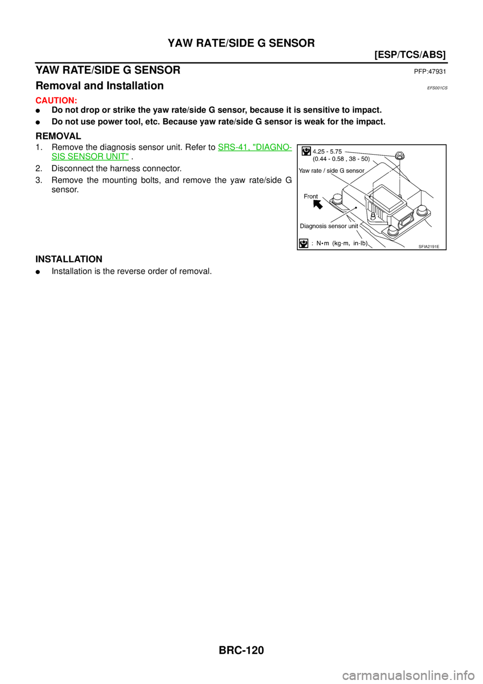
YAW RATE/SIDE G SENSOR
YAW RATE/SIDE G SENSORPFP:47931
Removal and InstallationEFS001CS
CAUTION:
�Do not drop or strike the yaw rate/side G sensor, because it is sensitive to impact.
�Do not use power tool, etc. Because yaw rate/side G sensor is weak for the impact.
REMOVAL
1. Remove the diagnosis sensor unit. Refer to SRS-41, "DIAGNO-
SIS SENSOR UNIT" .
2. Disconnect the harness connector.
3. Remove the mounting bolts, and remove the yaw rate/side G
sensor.
INSTALLATION
�Installation is the reverse order of removal.
SFIA2191E
Page 3170 of 4555
BRC-122
[ESP/TCS/ABS]
STEERING ANGLE SENSOR
STEERING ANGLE SENSORPFP:25554
Removal and InstallationEFS004HA
REMOVAL
1. Remove spiral cable assembly. Refer to SRS-33, "SPIRAL CABLE" .
2. Remove steering angle sensor from spiral cable assembly.
INSTALLATION
Install in the reverse order of removal.
NOTE:
After work, make sure to adjust neutral position of steering angle sensor. Refer to BRC-52, "
Adjustment of
Steering Angle Sensor Neutral Position" .
SFIA1404E
![NISSAN X-TRAIL 2005 Service Repair Manual BRC-122
[ESP/TCS/ABS]
STEERING ANGLE SENSOR
STEERING ANGLE SENSORPFP:25554
Removal and InstallationEFS004HA
REMOVAL
1. Remove spiral cable assembly. Refer to SRS-33, "SPIRAL CABLE" .
2. Remove steer](/manual-img/5/57403/w960_57403-3169.png "NISSAN X-TRAIL 2005 Service Repair Manual BRC-122
[ESP/TCS/ABS]
STEERING ANGLE SENSOR
STEERING ANGLE SENSORPFP:25554
Removal and InstallationEFS004HA
REMOVAL
1. Remove spiral cable assembly. Refer to SRS-33, \"SPIRAL CABLE\" .
2. Remove steer")