Page 3085 of 4555
![NISSAN X-TRAIL 2005 Service Repair Manual TROUBLE DIAGNOSIS
BRC-37
[ABS]
C
D
E
G
H
I
J
K
L
MA
B
BRC
5. CHECK WHEEL SENSOR HARNESS
1. Turn ignition switch OFF and disconnect malfunctioning wheel
sensor connector and ABS actuator and electric](/manual-img/5/57403/w960_57403-3084.png "NISSAN X-TRAIL 2005 Service Repair Manual TROUBLE DIAGNOSIS
BRC-37
[ABS]
C
D
E
G
H
I
J
K
L
MA
B
BRC
5. CHECK WHEEL SENSOR HARNESS
1. Turn ignition switch OFF and disconnect malfunctioning wheel
sensor connector and ABS actuator and electric")
TROUBLE DIAGNOSIS
BRC-37
[ABS]
C
D
E
G
H
I
J
K
L
MA
B
BRC
5. CHECK WHEEL SENSOR HARNESS
1. Turn ignition switch OFF and disconnect malfunctioning wheel
sensor connector and ABS actuator and electric unit (control
unit) connector.
2. Check continuity between terminals. (Also check continuity
when the steering wheel is turned right and left and when the
sensor harness inside the wheel house is moved.)
OK or NG
OK >> GO TO 6.
NG >> Repair or replace harness and connector that have malfunction.
6. CHECK WHEEL SENSOR
1. Replace wheel sensor that resulted in malfunction by self-diagnosis.
2. Reconnect connectors, drive vehicle at 30 km/h (19 MPH) or more for approximately 1 minute, and then
perform self-diagnosis.
Is above displayed on self-diagnosis display?
OK >> Wheel sensor has malfunction.
NG >>
�Replace ABS actuator and electric unit (control unit).
�Perform to self-diagnosis again, and make sure that the result shows “NO DTC IS DETECTED.
FURTHER TESTING MAY BE REQUIRED”.
SFIA2015E
Power supply circuit Signal circuit Ground circuit
WheelABS actua-
tor and
electric unit
(control
unit) har-
ness con-
nector E69Wheel sen-
sor har-
ness
connectorABS actua-
tor and
electric unit
(control
unit) har-
ness con-
nector E69Wheel sen-
sor har-
ness
connectorABS actuator and
electric unit (con-
trol unit) harness
connector E69
(Signal)Ground
Front RH
(E17)24 (W) 1 (W) 9 (B) 2 (B) 9 (B), 24 (W)
— Front LH
(E59)22 (L/W) 1 (L/W) 7 (L/Y) 2 (L/Y) 7 (L/Y), 22 (L/W)
Rear RH
(B130)28 (B/W) 1 (B/W) 13 (L/R) 2 (L/R) 13 (L/R), 28 (B/W)
Rear LH
(B126)26 (BR) 1 (BR) 11 (BR/W) 2 (BR/W) 11 (BR/W), 26 (BR)
Power supply circuit : Continuity should exist.
Signal circuit : Continuity should exist.
Ground circuit : Continuity should not exist.
Page 3089 of 4555
![NISSAN X-TRAIL 2005 Service Repair Manual TROUBLE DIAGNOSIS
BRC-41
[ABS]
C
D
E
G
H
I
J
K
L
MA
B
BRC
Inspection 6: G Sensor SystemEFS004HH
INSPECTION PROCEDURE
1. CHECK SELF-DIAGNOSIS RESULTS
Check the self-diagnostic results.
Is above displ](/manual-img/5/57403/w960_57403-3088.png "NISSAN X-TRAIL 2005 Service Repair Manual TROUBLE DIAGNOSIS
BRC-41
[ABS]
C
D
E
G
H
I
J
K
L
MA
B
BRC
Inspection 6: G Sensor SystemEFS004HH
INSPECTION PROCEDURE
1. CHECK SELF-DIAGNOSIS RESULTS
Check the self-diagnostic results.
Is above displ")
TROUBLE DIAGNOSIS
BRC-41
[ABS]
C
D
E
G
H
I
J
K
L
MA
B
BRC
Inspection 6: G Sensor SystemEFS004HH
INSPECTION PROCEDURE
1. CHECK SELF-DIAGNOSIS RESULTS
Check the self-diagnostic results.
Is above displayed on self-diagnosis display?
YES >> GO TO 2.
NO >> INSPECTION END
2. CHECK CONNECTOR
1. Turn ignition switch OFF, disconnect the ABS actuator and electric unit (control unit) and G sensor con-
nector, and check the terminal for deformation, disconnection, looseness, and so on. If there is a malfunc-
tion, repair or replace the terminal.
2. Reconnect connector securely, and perform self-diagnosis.
OK or NG
OK >> Poor connection of connector terminal
NG >> GO TO 3.
3. CHECK CIRCUIT BETWEEN G SENSOR AND ABS ACTUATOR AND ELECTRIC UNIT
1. Turn ignition switch OFF and disconnect G sensor and ABS actuator and electric unit (control unit) con-
nectors.
2. Check continuity between G sensor harness connector M57 and ABS actuator and electric unit (control
unit) harness connector E69.
OK or NG
OK >> GO TO 4.
NG >> Circuit malfunction of G sensor. Repair harness.
Self-diagnostic results
G - SENSOR
G sensor harness
connector M57ABS actuator and
electric unit (control
unit) harness con-
nector E69Measured
value
1 (B/W) 21 (B)
Continuity
should
exist. 2 (R/L) 12 (R/L)
3 (PU/W) 10 (PU/W)
4 (SB) 25 (SB)
SFIA2024E
Page 3090 of 4555
BRC-42
[ABS]
TROUBLE DIAGNOSIS
4. CHECK G SENSOR POWER SUPPLY CIRCUIT
1. Turn ignition switch ON.
2. Check voltage between G sensor harness connector M57 termi-
nal 5 (L) and ground.
OK or NG
OK >> GO TO 5.
NG >> G sensor power supply circuit malfunction. Repair circuit.
5. CHECK G SENSOR
1. Remove G sensor from the vehicle. Refer to BRC-47, "
G SENSOR" .
2. Connect the following terminals between G sensor and connec-
tor.
3. Check voltage between the following G sensor terminals when
ignition switch turns ON and G sensor is in the following condi-
tion.Voltage : Battery voltage (Approx. 12V)
SFIA2025E
G sensor connector Harness connector M57
11 (B)
2 2 (R/L)
5 5 (L)
SFIA2026E
G sensor statusG sensor har-
ness connector
M57 terminals 5
(L) - 4 (SB)G sensor har-
ness connector
M57 terminals 5
(L) - 3 (PU/W)
Horizontal Approx. 5V Approx. 5V
Longitudinally
tilt by 20°Approx. 10V Approx. 10V
Longitudinally
tilt by 40°Approx. 5V Approx. 10V
SFIA2027E
Page 3091 of 4555
![NISSAN X-TRAIL 2005 Service Repair Manual TROUBLE DIAGNOSIS
BRC-43
[ABS]
C
D
E
G
H
I
J
K
L
MA
B
BRC
OK or NG
OK >> ABS actuator and electric unit (control unit) malfunction. Replace ABS actuator and electric unit
(control unit).
NG >> G sen](/manual-img/5/57403/w960_57403-3090.png "NISSAN X-TRAIL 2005 Service Repair Manual TROUBLE DIAGNOSIS
BRC-43
[ABS]
C
D
E
G
H
I
J
K
L
MA
B
BRC
OK or NG
OK >> ABS actuator and electric unit (control unit) malfunction. Replace ABS actuator and electric unit
(control unit).
NG >> G sen")
TROUBLE DIAGNOSIS
BRC-43
[ABS]
C
D
E
G
H
I
J
K
L
MA
B
BRC
OK or NG
OK >> ABS actuator and electric unit (control unit) malfunction. Replace ABS actuator and electric unit
(control unit).
NG >> G sensor malfunction. Replace G sensor.
Inspection 7: CAN Communication SystemEFS004HI
INSPECTION PROCEDURE
1. CHECK CONNECTOR
1. Turn ignition switch OFF, disconnect the ABS actuator and electric unit (control unit) connector, and check
the terminal for deformation, disconnection, looseness, and so on. If there is a malfunction, repair or
replace the terminal.
2. Reconnect connector to perform self-diagnosis.
Is
“CAN COMM CIRCUIT” displayed in the self-diagnosis display items?
YES >> Print out the self-diagnostic results, and refer to BRC-8, "CAN COMMUNICATION" .
NO >> Connector terminal connector is loose, damaged, open, or shorted.
Symptom 1: ABS Works FrequentlyEFS004HJ
1. CHECK START
Check longitudinal brake force distribution using a brake tester.
OK or NG
OK >> GO TO 2.
NG >> Check brake system.
2. CHECK FRONT AND REAR AXLE
Check to make sure that there is no excessive play in the front and rear axles. Refer to Front: FAX-7, "
On-
Vehicle Inspection" , Rear: RAX-6, "WHEEL BEARING INSPECTION" (2WD), RAX-10, "REAR WHEEL
BEARING" (4WD).
OK or NG
OK >> GO TO 3.
NG >> Repair.
3. CHECK WHEEL SENSOR AND SENSOR ROTOR
Check wheel sensor and sensor rotor for the following.
�Sensor installation for damage
�Sensor rotor installation for damage
�Sensor connector engagement
�Sensor harness
OK or NG
OK >> GO TO 4.
NG >>
�Replace wheel sensor or sensor rotor.
�Repair harness.
4. CHECK ABS WARNING LAMP DISPLAY
Make sure that the warning lamp turns off approximately 1 second after the key switch is turned on or when
driving.
OK or NG
OK >> Normal
NG >> Perform self-diagnosis. Refer to BRC-28, "
SELF-DIAGNOSIS" .
Page 3092 of 4555
![NISSAN X-TRAIL 2005 Service Repair Manual BRC-44
[ABS]
TROUBLE DIAGNOSIS
Symptom 2: Unexpected Pedal ReactionEFS004HK
1. CHECK BRAKE PEDAL STROKE
Check brake pedal stroke. Refer to BR-6, "
On-Vehicle Inspection and Adjustment" .
Is the stro](/manual-img/5/57403/w960_57403-3091.png "NISSAN X-TRAIL 2005 Service Repair Manual BRC-44
[ABS]
TROUBLE DIAGNOSIS
Symptom 2: Unexpected Pedal ReactionEFS004HK
1. CHECK BRAKE PEDAL STROKE
Check brake pedal stroke. Refer to BR-6, \"
On-Vehicle Inspection and Adjustment\" .
Is the stro")
BRC-44
[ABS]
TROUBLE DIAGNOSIS
Symptom 2: Unexpected Pedal ReactionEFS004HK
1. CHECK BRAKE PEDAL STROKE
Check brake pedal stroke. Refer to BR-6, "
On-Vehicle Inspection and Adjustment" .
Is the stroke too large?
YES >>�Bleed air from the brake piping. Refer to BR-9, "Bleeding Brake System" .
�Check brake pedal, brake booster, and master cylinder for mount play, looseness, brake sys-
tem fluid leakage, etc. Repair if necessary. Refer to Brake pedal: BR-7, "
Components" , brake
booster and master cylinder: BR-23, "
Removal and Installation" .
NO >> GO TO 2.
2. PERFORMANCE CHECK
Disconnect ABS actuator and electric unit (control unit) connector to deactivate ABS. Check if braking force is
normal in this condition. Connect connector after inspection.
OK or NG
OK >> GO TO 3. Wheel Sensor Inspection in BRC-43, "Symptom 1: ABS Works Frequently" .
NG >> Check brake system.
Symptom 3: Longer Stopping DistanceEFS004HL
CAUTION:
The stopping distance on slippery road surfaces might be longer with the ABS operating than when
the ABS is not operating.
1. PERFORMANCE CHECK
Turn ignition switch OFF. Disconnect ABS actuator and electric unit (control unit) connector to deactivate ABS.
In this condition, check stopping distance. After inspection, connect connector.
OK or NG
OK >> GO TO BRC-43, "Symptom 1: ABS Works Frequently" .
NG >>
�Bleed air from the brake piping. Refer to BR-9, "Bleeding Brake System" .
�Check brake system.
Page 3093 of 4555
![NISSAN X-TRAIL 2005 Service Repair Manual TROUBLE DIAGNOSIS
BRC-45
[ABS]
C
D
E
G
H
I
J
K
L
MA
B
BRC
Symptom 4: ABS Does Not WorkEFS004HM
CAUTION:
ABS does not operate when speed is 10 km/h or lower.
1. CHECK ABS WARNING LAMP DISPLAY
Make su](/manual-img/5/57403/w960_57403-3092.png "NISSAN X-TRAIL 2005 Service Repair Manual TROUBLE DIAGNOSIS
BRC-45
[ABS]
C
D
E
G
H
I
J
K
L
MA
B
BRC
Symptom 4: ABS Does Not WorkEFS004HM
CAUTION:
ABS does not operate when speed is 10 km/h or lower.
1. CHECK ABS WARNING LAMP DISPLAY
Make su")
TROUBLE DIAGNOSIS
BRC-45
[ABS]
C
D
E
G
H
I
J
K
L
MA
B
BRC
Symptom 4: ABS Does Not WorkEFS004HM
CAUTION:
ABS does not operate when speed is 10 km/h or lower.
1. CHECK ABS WARNING LAMP DISPLAY
Make sure that the warning lamp turns off approximately 1 second after the key switch is turned on or when
driving.
OK or NG
OK >> GO TO 3. Check wheel sensor and sensor rotor in BRC-43, "Symptom 1: ABS Works Frequently"
.
NG >> Perform self-diagnosis. Refer to BRC-28, "
SELF-DIAGNOSIS" .
Symptom 5: Pedal Vibration and ABS Operation NoiseEFS004HN
CAUTION:
Under the following conditions, ABS is activated and vibration is felt when brake pedal is lightly
depressed (just place a foot on it). However, this is normal.
�When shifting gears
�When driving on slippery road
�During cornering at high speed
�When passing over bumps or grooves (Approx. 50 mm or more)
�When pulling away just after starting engine (Approx. 10 km/h or more)
1. SYMPTOM CHECK 1
Check if pedal vibration or operation sounds occur when the engine is started.
OK or NG
OK >> GO TO 2.
NG >> Perform self-diagnosis. Refer to BRC-28, "
SELF-DIAGNOSIS" .
2. SYMPTOM CHECK 2
Check symptoms when electrical component (headlamps, etc.) Switches are operated.
Do symptoms occur?
YES >> Check if there is a radio, antenna, antenna lead wire, or wiring close to the control unit. If there is,
move it farther away.
NG >> GO TO 3. Check wheel sensor and sensor rotor in BRC-43, "
Symptom 1: ABS Works Frequently"
.
Page 3094 of 4555
![NISSAN X-TRAIL 2005 Service Repair Manual BRC-46
[ABS]
WHEEL SENSORS
WHEEL SENSORSPFP:47910
Removal and InstallationEFS004GR
REMOVAL
Pay attention to the following when removing sensor.
CAUTION:
�As much as possible, avoid rotating sensor w](/manual-img/5/57403/w960_57403-3093.png "NISSAN X-TRAIL 2005 Service Repair Manual BRC-46
[ABS]
WHEEL SENSORS
WHEEL SENSORSPFP:47910
Removal and InstallationEFS004GR
REMOVAL
Pay attention to the following when removing sensor.
CAUTION:
�As much as possible, avoid rotating sensor w")
BRC-46
[ABS]
WHEEL SENSORS
WHEEL SENSORSPFP:47910
Removal and InstallationEFS004GR
REMOVAL
Pay attention to the following when removing sensor.
CAUTION:
�As much as possible, avoid rotating sensor when removing it. Pull sensors out without pulling on
sensor harness.
�Take care to avoid damaging sensor edges or rotor teeth. Remove wheel sensor first before
removing front or rear wheel hub. This is to avoid damage to sensor wiring and loss of sensor
function.
INSTALLATION
Pay attention to the following when installing sensor. Tighten installation bolts to specified torques.
�When installing, check that there is no foreign material such as iron chips on pick-up and mounting hole of
the sensor. Check that no foreign material has been caught in the sensor rotor. Remove any foreign mate-
rial and clean the mount.
�When installing front sensor, be sure to press rubber grommets in until they lock at the three locations
shown in the figure (2 at strut and 1 at body panel). When installed, harness must not be twisted.
SFIA1100E
Page 3095 of 4555
G SENSOR
BRC-47
[ABS]
C
D
E
G
H
I
J
K
L
MA
B
BRC
G SENSORPFP:47930
Removal and InstallationEFS004GY
CAUTION:
�Do not drop or strike the G sensor, because it is sensitive to impact.
�Do not use power tool, etc. Because G sensor is weak for the impact.
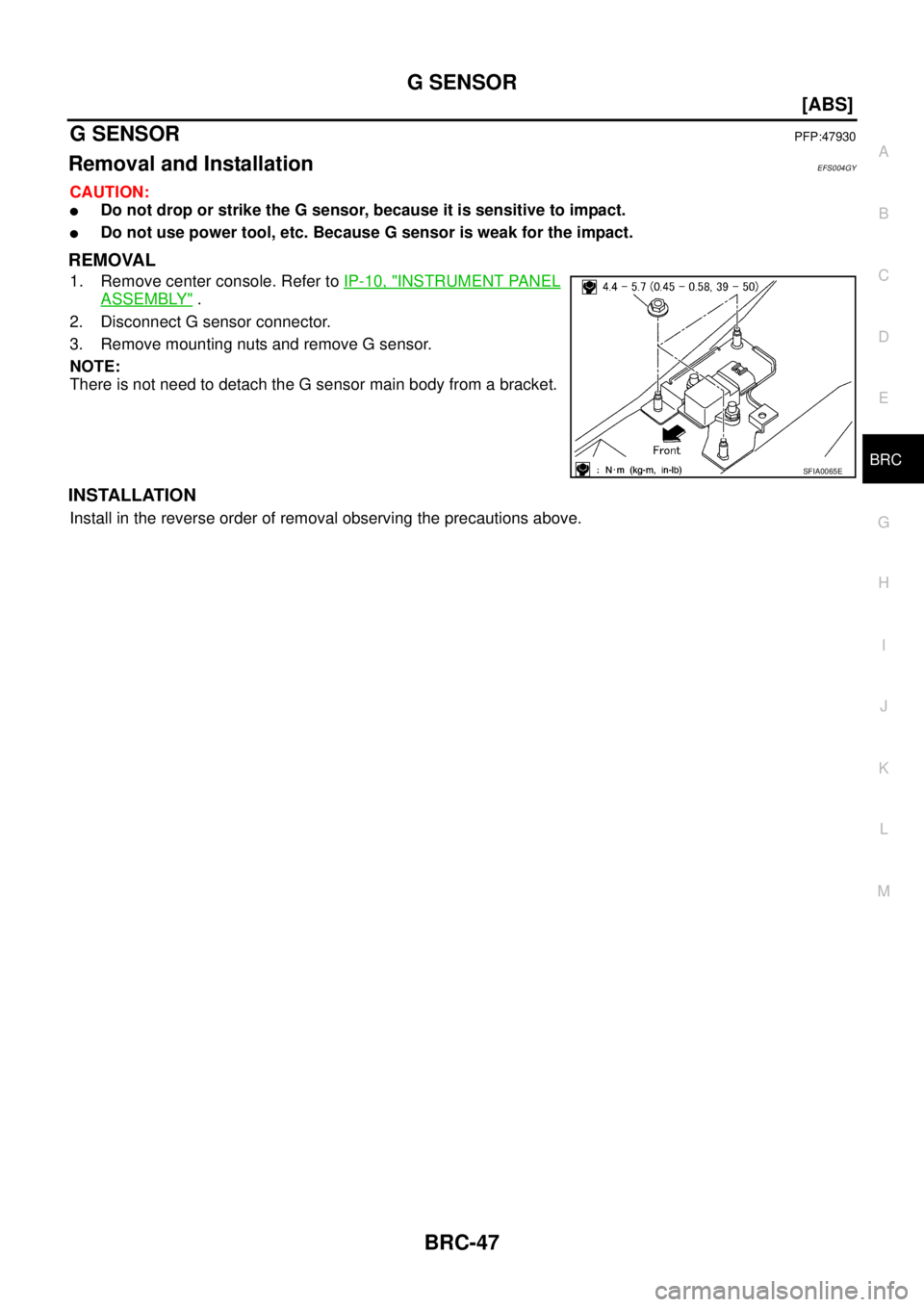
REMOVAL
1. Remove center console. Refer to IP-10, "INSTRUMENT PANEL
ASSEMBLY" .
2. Disconnect G sensor connector.
3. Remove mounting nuts and remove G sensor.
NOTE:
There is not need to detach the G sensor main body from a bracket.
INSTALLATION
Install in the reverse order of removal observing the precautions above.
SFIA0065E
![NISSAN X-TRAIL 2005 Service Repair Manual BRC-42
[ABS]
TROUBLE DIAGNOSIS
4. CHECK G SENSOR POWER SUPPLY CIRCUIT
1. Turn ignition switch ON.
2. Check voltage between G sensor harness connector M57 termi-
nal 5 (L) and ground.
OK or NG
OK >>](/manual-img/5/57403/w960_57403-3089.png "NISSAN X-TRAIL 2005 Service Repair Manual BRC-42
[ABS]
TROUBLE DIAGNOSIS
4. CHECK G SENSOR POWER SUPPLY CIRCUIT
1. Turn ignition switch ON.
2. Check voltage between G sensor harness connector M57 termi-
nal 5 (L) and ground.
OK or NG
OK >>")