2005 NISSAN NAVARA FL-
[x] Cancel search: FL-Page 257 of 3171

TRANSMISSION ASSEMBLY
AT-249
D
E
F
G
H
I
J
K
L
MA
B
AT
5. Remove front valance center, engine undercover front, engine under cover middle and engine under
coverrear.RefertoEI-15, "
FRONT BUMPER".
6. Remove front cross member.
7. Remove main muffler. Refer toEX-2, "
EXHAUST SYSTEM".
8. Remove rear propeller shaft. Refer toPR-8, "
Removal and Installation".
9. Remove front propeller shaft. Refer toPR-4, "
Removal and Installation".
10. Remove starter motor. Refer toSC-31, "
Removal and Installation".
11. Remove control cable and bracket. Refer toAT- 2 1 0 , "
Control Cable Removal and Installation".
12. Disconnect fluid cooler tube.
13. Remove A/T fluid charging pipe from A/T assembly.
14. Remove O-ring from A/T fluid charging pipe.
15. Plug up openings such as A/T fluid charging pipe hole, etc.
16. Remove rear plate cover from rear plate.
17. Turn crankshaft to access and remove the four bolts for drive
plate and torque converter.
CAUTION:
When turning crankshaft, turn it clockwise as viewed from
the front of engine.
18. Support A/T assembly using a transmission jack.
CAUTION:
When setting transmission jack, be careful not to allow it to
collide against drain plug.
19. Remove protector (fuel tube), and then disconnect fuel tubes.
Refer toFL-7, "
FUEL COOLER". (4WD models)
20. Remove A/T cross member.
21. Remove engine mounting insulator (rear) from A/T assembly.
22. Disconnect the following:
lA/T assembly harness connector
lATP switch connector
l4LO switch connector
lWait detection switch connector
lTransfer control device connector
23. Support transfer assembly using a transmission jack. (4WD models)
24. Remove the wiring harness from bracket.
25. Remove bolts fixing A/T assembly to engine assembly.
26. Remove A/T assembly from the vehicle.
CAUTION:
lSecure torque converter to prevent it from dropping.
lSecure A/T assembly to a transmission jack.
27. Remove A/T air breather hose. Refer toAT- 2 4 3 , "
AIR
BREATHER HOSE".
28. Remove transfer assembly from A/T assembly. Refer toT F - 111 ,
"Removal and Installation". (4WD models)
SCIA6828E
SCIA6927E
SCIA2203E
Page 932 of 3171
DI-22
COMBINATION METERS
Fuel Level Sensor Signal Inspection
EKS00L8U
Symptom:
lFuel gauge indication is malfunction.
lLow-fuel warning lamp indication is irregular.
NOTE:
The following symptoms are not malfunction.
Fuel level sensor unit
lDepending on vehicle incline or driving circumstance, the fuel level in the tank varies, and the pointer may
fluctuate.
lIf the vehicle is fueled with the ignition switch ON, the pointer moves slowly.
Low-fuel warning lamp
lDepending on vehicle incline or driving circumstance, the fuel in the tank flows and the warning lamp ON
timing may change.
1.CHECK COMBINATION METER INPUT SIGNAL
1. Select “METER” on CONSULT-II.
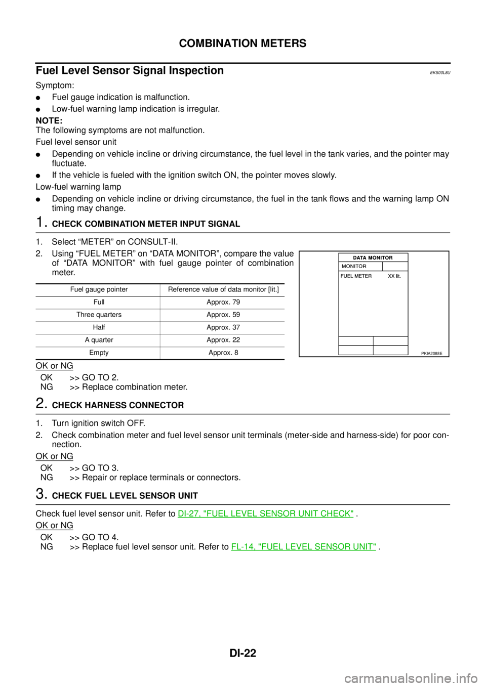
2. Using “FUEL METER” on “DATA MONITOR”, compare the value
of “DATA MONITOR” with fuel gauge pointer of combination
meter.
OK or NG
OK >> GO TO 2.
NG >> Replace combination meter.
2.CHECK HARNESS CONNECTOR
1. Turn ignition switch OFF.
2. Check combination meter and fuel level sensor unit terminals (meter-side and harness-side) for poor con-
nection.
OK or NG
OK >> GO TO 3.
NG >> Repair or replace terminals or connectors.
3.CHECK FUEL LEVEL SENSOR UNIT
Check fuel level sensor unit. Refer toDI-27, "
FUEL LEVEL SENSOR UNIT CHECK".
OK or NG
OK >> GO TO 4.
NG >> Replace fuel level sensor unit. Refer toFL-14, "
FUEL LEVEL SENSOR UNIT".
Fuel gauge pointer Reference value of data monitor [lit.]
Full Approx. 79
Three quarters Approx. 59
Half Approx. 37
A quarter Approx. 22
Empty Approx. 8
PKIA2088E
Page 937 of 3171
COMBINATION METERS
DI-27
C
D
E
F
G
H
I
J
L
MA
B
DI
Electrical Components InspectionEKS00L8Z
FUEL LEVEL SENSOR UNIT CHECK
For removal, refer toFL-14, "FUEL LEVEL SENSOR UNIT".
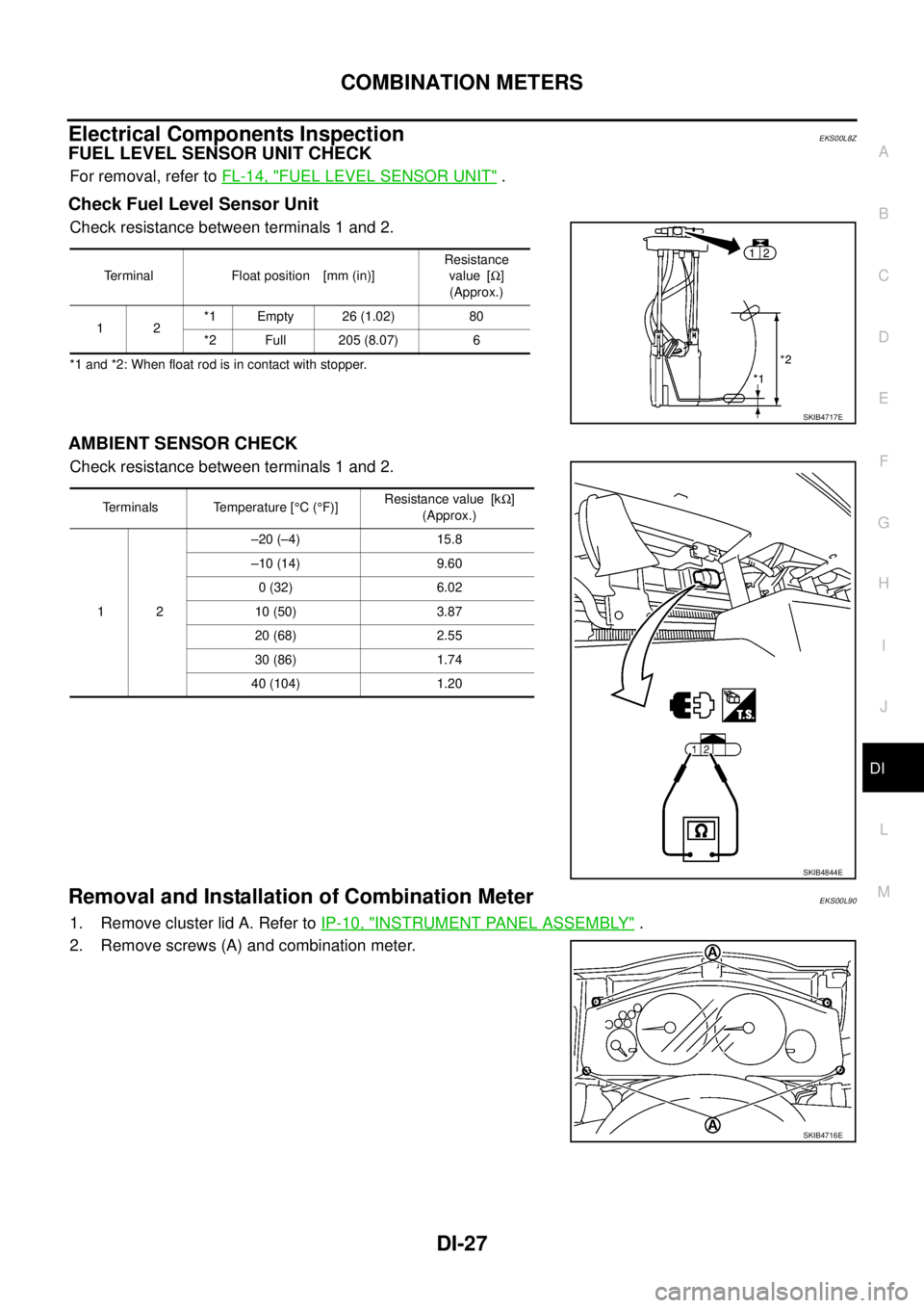
Check Fuel Level Sensor Unit
Check resistance between terminals 1 and 2.
*1 and *2: When float rod is in contact with stopper.
AMBIENT SENSOR CHECK
Check resistance between terminals 1 and 2.
Removal and Installation of Combination MeterEKS00L90
1. Remove cluster lid A. Refer toIP-10, "INSTRUMENT PANEL ASSEMBLY".
2. Remove screws (A) and combination meter.
Terminal Float position [mm (in)]Resistance
value [W]
(Approx.)
12*1 Empty 26 (1.02) 80
*2 Full 205 (8.07) 6
SKIB4717E
Terminals Temperature [°C(°F)]Resistance value [kW]
(Approx.)
12–20 (–4) 15.8
–10 (14) 9.60
0 (32) 6.02
10 (50) 3.87
20 (68) 2.55
30 (86) 1.74
40 (104) 1.20
SKIB4844E
SKIB4716E
Page 1403 of 3171
INTAKE MANIFOLD
EM-21
C
D
E
F
G
H
I
J
K
L
MA
EM
lRefer toGI-10, "Components"for symbol marks except in the above.
Removal and InstallationEBS01EJF
REMOVAL
WARNING:
To avoid the danger of being scalded, do not drain engine coolant when engine is hot.
1. Drain engine coolant. Refer toCO-7, "
Changing Engine Coolant".
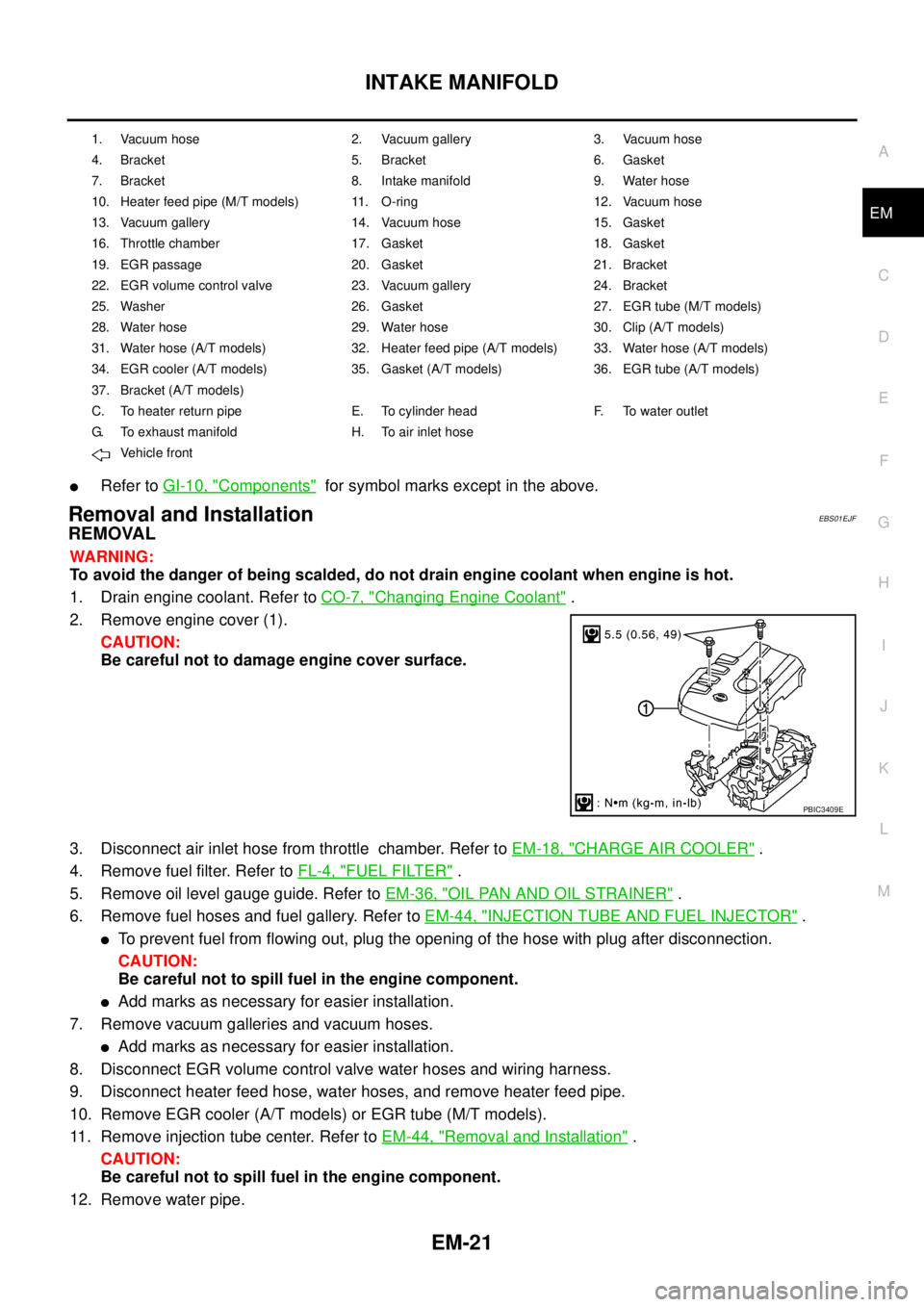
2. Remove engine cover (1).
CAUTION:
Be careful not to damage engine cover surface.
3. Disconnect air inlet hose from throttle chamber. Refer toEM-18, "
CHARGE AIR COOLER".
4. Remove fuel filter. Refer toFL-4, "
FUEL FILTER".
5. Remove oil level gauge guide. Refer toEM-36, "
OIL PAN AND OIL STRAINER".
6. Remove fuel hoses and fuel gallery. Refer toEM-44, "
INJECTION TUBE AND FUEL INJECTOR".
lTo prevent fuel from flowing out, plug the opening of the hose with plug after disconnection.
CAUTION:
Be careful not to spill fuel in the engine component.
lAdd marks as necessary for easier installation.
7. Remove vacuum galleries and vacuum hoses.
lAdd marks as necessary for easier installation.
8. Disconnect EGR volume control valve water hoses and wiring harness.
9. Disconnect heater feed hose, water hoses, and remove heater feed pipe.
10. Remove EGR cooler (A/T models) or EGR tube (M/T models).
11. Remove injection tube center. Refer toEM-44, "
Removal and Installation".
CAUTION:
Be careful not to spill fuel in the engine component.
12. Remove water pipe.
1. Vacuum hose 2. Vacuum gallery 3. Vacuum hose
4. Bracket 5. Bracket 6. Gasket
7. Bracket 8. Intake manifold 9. Water hose
10. Heater feed pipe (M/T models) 11. O-ring 12. Vacuum hose
13. Vacuum gallery 14. Vacuum hose 15. Gasket
16. Throttle chamber 17. Gasket 18. Gasket
19. EGR passage 20. Gasket 21. Bracket
22. EGR volume control valve 23. Vacuum gallery 24. Bracket
25. Washer 26. Gasket 27. EGR tube (M/T models)
28. Water hose 29. Water hose 30. Clip (A/T models)
31. Water hose (A/T models) 32. Heater feed pipe (A/T models) 33. Water hose (A/T models)
34. EGR cooler (A/T models) 35. Gasket (A/T models) 36. EGR tube (A/T models)
37. Bracket (A/T models)
C. To heater return pipe E. To cylinder head F. To water outlet
G. To exhaust manifold H. To air inlet hose
Vehicle front
PBIC3409E
Page 1407 of 3171
INTAKE MANIFOLD
EM-25
C
D
E
F
G
H
I
J
K
L
MA
EM
–When an insert stopper is not provided with the pipe, insert the hose up to dimension A. When the pipe is
shorter than dimension A, insert hose fully until it reaches the end.
–When an insert stopper is provided on the pipe side, insert the hose until it reaches the stopper.
lBefore starting engine, bleed air from fuel piping. Refer toFL-5, "Air Bleeding".
INSPECTION AFTER INSTALLATION
Start engine and increase engine speed to check for fuel leak.
CAUTION:
Do not touch the engine immediately after stopped as engine becomes extremely hot.
NOTE:
Use mirrors for checking at points out of clear sight.Dimension A : 15 – 20 mm (0.591 – 0.787 in)
Page 1426 of 3171
EM-44
INJECTION TUBE AND FUEL INJECTOR
INJECTION TUBE AND FUEL INJECTOR
PFP:00018
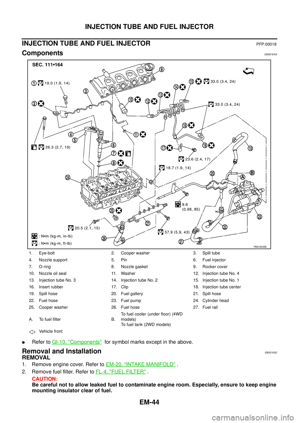
ComponentsEBS01EK6
lRefer toGI-10, "Components"for symbol marks except in the above.
Removal and InstallationEBS01E63
REMOVAL
1. Remove engine cover. Refer toEM-20, "INTAKE MANIFOLD".
2. Remove fuel filter. Refer toFL-4, "
FUEL FILTER".
CAUTION:
Be careful not to allow leaked fuel to contaminate engine room. Especially, ensure to keep engine
mounting insulator clear of fuel.
1. Eye-bolt 2. Cooper washer 3. Spill tube
4. Nozzle support 5. Pin 6. Fuel injector
7. O-ring 8. Nozzle gasket 9. Rocker cover
10. Nozzle oil seal 11. Washer 12. Injection tube No. 4
13. Injection tube No. 3 14. Injection tube No. 2 15. Injection tube No. 1
16. Insert rubber 17. Clip 18. Injection tube center
19. Spill hose 20. Fuel gallery 21. Spill hose
22. Fuel hose 23. Fuel pump 24. Cylinder head
25. Cooper washer 26. Fuel hose 27. Fuel rail
A. To fuel filter B.To fuel cooler (under floor) (4WD
models)
To fuel tank (2WD models)
Vehicle front
PBIC4046E
Page 1439 of 3171
ROCKER COVER
EM-57
C
D
E
F
G
H
I
J
K
L
MA
EM
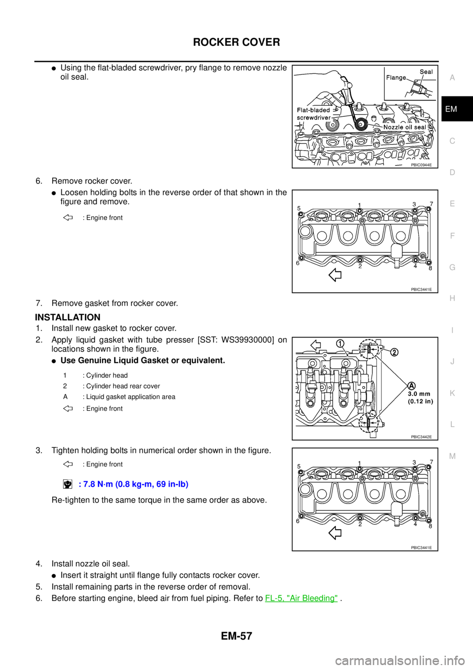
lUsing the flat-bladed screwdriver, pry flange to remove nozzle
oil seal.
6. Remove rocker cover.
lLoosen holding bolts in the reverse order of that shown in the
figure and remove.
7. Remove gasket from rocker cover.
INSTALLATION
1. Install new gasket to rocker cover.
2. Apply liquid gasket with tube presser [SST: WS39930000] on
locations shown in the figure.
lUse Genuine Liquid Gasket or equivalent.
3. Tighten holding bolts in numerical order shown in the figure.
Re-tighten to the same torque in the same order as above.
4. Install nozzle oil seal.
lInsert it straight until flange fully contacts rocker cover.
5. Install remaining parts in the reverse order of removal.
6. Before starting engine, bleed air from fuel piping. Refer toFL-5, "
Air Bleeding".
PBIC0944E
: Engine front
PBIC3441E
1 : Cylinder head
2 : Cylinder head rear cover
A : Liquid gasket application area
: Engine front
PBIC3442E
: Engine front
: 7.8 N·m (0.8 kg-m, 69 in-lb)
PBIC3441E
Page 1489 of 3171
ENGINE ASSEMBLY
EM-107
C
D
E
F
G
H
I
J
K
L
MA
EM
lFor supporting points for lifting and jacking point at rear axle, refer toGI-52, "Pantograph Jack,
Garage Jack and Safety Stand".
REMOVAL
Description of work
Remove transmission assembly from vehicle downward. Then hoist the engine from vehicle upward.
Preparation
1. Disconnect battery cable from negative terminal. Refer toSC-5, "BATTERY".
2. Drain engine coolant from radiator drain plug. Refer toCO-7, "
Changing Engine Coolant".
3. Remove the following parts.
lEngine undercover front, engine undercover middle, engine undercover rear; Refer toEI-15, "FRONT
BUMPER".
lHood assembly; Refer toBL-12, "HOOD".
lEngine cover; Refer toEM-20, "INTAKE MANIFOLD".
lDrive belts; Refer toEM-12, "DRIVE BELTS".
lCooling fan, fan coupling and water pump pulley; Refer toCO-19, "COOLING FAN".
lAir duct and air cleaner case; Refer toEM-15, "AIR CLEANER AND AIR DUCT".
lAir inlet tube and air inlet hose; Refer toEM-18, "CHARGE AIR COOLER".
lAlternator; Refer toSC-23, "Removal and Installation".
lRadiator, radiator shroud (upper and lower) and cooling fan assembly; Refer toCO-11, "RADIATOR"
andCO-19, "COOLING FAN".
4. Disconnect engine room harness from the engine side and set it aside for easier work.
5. Disconnect all the body-side vacuum hoses and air hoses at engine side.
Engine room RH
1. Disconnect fuel feed hose and return hose, and plug it to prevent fuel from draining. Refer toEM-44,
"INJECTION TUBE AND FUEL INJECTOR".
2. Remove fuel filter. Refer toFL-4, "
FUEL FILTER".
3. Disconnect heater hose, and install plug it to prevent engine coolant from draining. Refer toCO-23,
"THERMOSTAT AND WATER PIPING".
Engine room LH
1. Remove A/C compressor with piping connected from engine. Temporarily secure it on body with a rope to
avoid putting load on it. Refer toATC-142, "
Removal and Installation for Compressor"(automatic A/C
models) orMTC-122, "
Removal and Installation for Compressor"(manual A/C models).
Vehicle underbody
1. Remove exhaust front tube. Refer toEX-3, "Removal and Installation".
2. Remove front propeller shaft (4WD models) and rear propeller shaft. Refer toPR-3, "
FRONT PROPEL-
LER SHAFT"(4WD models) andPR-7, "REAR PROPELLER SHAFT".
3. Remove clutch operating cylinder from transmission, and move it aside (M/T models). Refer toMT-16,
"TRANSMISSION ASSEMBLY"andCL-11, "OPERATING CYLINDER".
4. Disconnect power steering fluid piping at a point between body and engine. Refer toPS-30, "
HYDRAULIC
LINE".
5. Remove starter motor. Refer toSC-31, "
Removal and Installation".
6. Remove transmission assembly. Refer toMT-16, "
TRANSMISSION ASSEMBLY"(M/T models) orAT-
247, "TRANSMISSION ASSEMBLY"(A/T models).