2005 NISSAN NAVARA battery
[x] Cancel search: batteryPage 3052 of 3171
TROUBLE DIAGNOSIS FOR SYSTEM
TF-85
C
E
F
G
H
I
J
K
L
MA
B
TF
COMPONENT INSPECTION
1. Turn ignition switch “OFF”. (Stay for at least 5 seconds.)
2. Disconnect ATP switch harness connector.
3. Remove ATP switch. Refer toTF-21, "
Location of Electrical Parts".
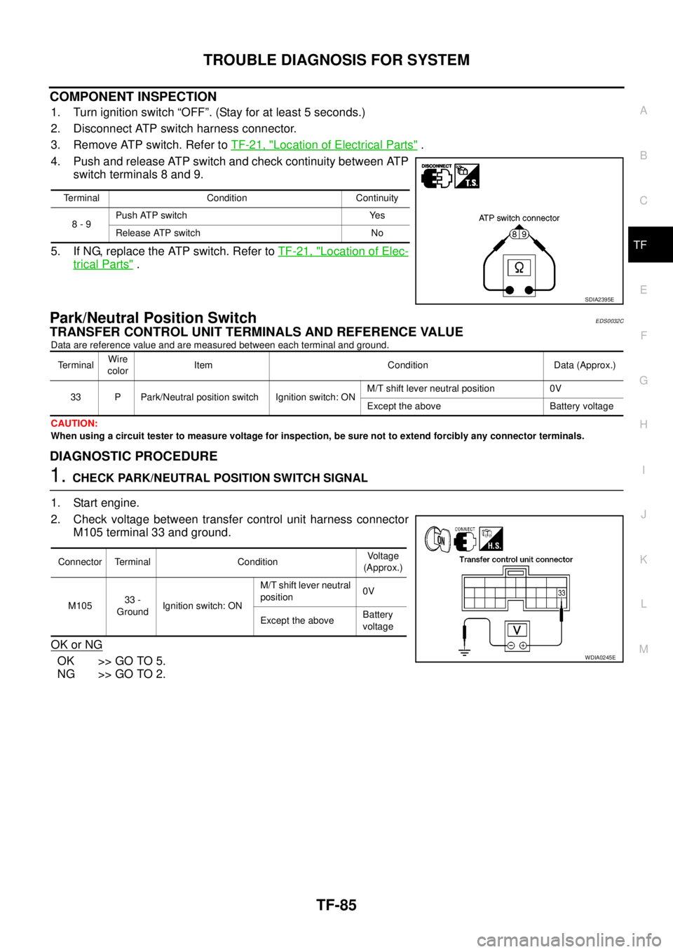
4. Push and release ATP switch and check continuity between ATP
switch terminals 8 and 9.
5. If NG, replace the ATP switch. Refer toTF-21, "
Location of Elec-
trical Parts".
Park/Neutral Position SwitchEDS0032C
TRANSFER CONTROL UNIT TERMINALS AND REFERENCE VALUE
Data are reference value and are measured between each terminal and ground.
CAUTION:
When using a circuit tester to measure voltage for inspection, be sure not to extend forcibly any connector terminals.
DIAGNOSTIC PROCEDURE
1.CHECK PARK/NEUTRAL POSITION SWITCH SIGNAL
1. Start engine.
2. Check voltage between transfer control unit harness connector
M105 terminal 33 and ground.
OK or NG
OK >> GO TO 5.
NG >> GO TO 2.
Terminal Condition Continuity
8-9Push ATP switch Yes
Release ATP switch No
SDIA2395E
TerminalWire
colorItem Condition Data (Approx.)
33 P Park/Neutral position switch Ignition switch: ONM/T shift lever neutral position 0V
Except the above Battery voltage
Connector Terminal ConditionVoltage
(Approx.)
M10533 -
GroundIgnition switch: ONM/T shift lever neutral
position0V
Except the aboveBattery
voltage
WDIA0245E
Page 3056 of 3171
TROUBLE DIAGNOSIS FOR SYMPTOMS
TF-89
C
E
F
G
H
I
J
K
L
MA
B
TF
DIAGNOSTIC PROCEDURE
1.CHECK TRANSFER CONTROL UNIT POWER SUPPLY CIRCUIT
1. Turn ignition switch “OFF”. (Stay for at least 5 seconds.)
2. Disconnect transfer control unit harness connector.
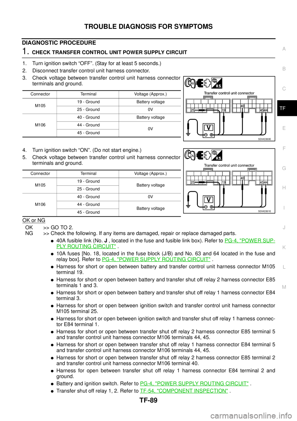
3. Check voltage between transfer control unit harness connector
terminals and ground.
4. Turn ignition switch “ON”. (Do not start engine.)
5. Check voltage between transfer control unit harness connector
terminals and ground.
OK or NG
OK >> GO TO 2.
NG >> Check the following. If any items are damaged, repair or replace damaged parts.
l40A fusible link (No.J, located in the fuse and fusible link box). Refer toPG-4, "POWER SUP-
PLY ROUTING CIRCUIT".
l10A fuses [No. 18, located in the fuse block (J/B) and No. 63 and 64 located in the fuse and
relay box]. Refer toPG-4, "
POWER SUPPLY ROUTING CIRCUIT".
lHarness for short or open between battery and transfer control unit harness connector M105
terminal 19.
lHarness for short or open between battery and transfer shut off relay 2 harness connector E85
terminals 1 and 3.
lHarness for short or open between battery and transfer shut off relay 1 harness connector E84
terminal 3.
lHarness for short or open between ignition switch and transfer control unit harness connector
M105 terminal 25.
lHarness for short or open between ignition switch and transfer shut off relay 1 harness connec-
tor E84 terminal 1.
lHarness for short or open between transfer shut off relay 2 harness connector E85 terminal 5
and transfer control unit harness connector M106 terminals 44, 45.
lHarness for short or open between transfer shut off relay 1 harness connector E84 terminal 5
and transfer control unit harness connector M106 terminals 44, 45.
lHarness for short or open between transfer shut off relay 2 harness connector E85 terminal 2
and transfer control unit harness connector M106 terminal 40.
lHarness for open between transfer shut off relay 1 harness connector E84 terminal 2 and
ground.
lBattery and ignition switch. Refer toPG-4, "POWER SUPPLY ROUTING CIRCUIT".
lTransfer shut off relay 1, 2. Refer toTF-54, "COMPONENT INSPECTION".
Connector Terminal Voltage (Approx.)
M10519 - Ground Battery voltage
25 - Ground 0V
M10640 - Ground Battery voltage
44 - Ground
0V
45 - Ground
SDIA3360E
Connector Terminal Voltage (Approx.)
M10519 - Ground
Battery voltage
25 - Ground
M10640 - Ground 0V
44 - Ground
Battery voltage
45 - Ground
SDIA3361E
Page 3057 of 3171
TF-90
TROUBLE DIAGNOSIS FOR SYMPTOMS
2.CHECK TRANSFER CONTROL UNIT GROUND CIRCUIT
1. Turn ignition switch “OFF”. (Stay for at least 5 seconds.)
2. Disconnect transfer control unit harness connectors.
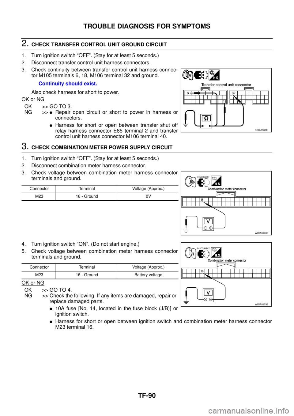
3. Check continuity between transfer control unit harness connec-
tor M105 terminals 6, 18, M106 terminal 32 and ground.
Also check harness for short to power.
OK or NG
OK >> GO TO 3.
NG >>
lRepair open circuit or short to power in harness or
connectors.
lHarness for short or open between transfer shut off
relay harness connector E85 terminal 2 and transfer
control unit harness connector M106 terminal 40.
3.CHECK COMBINATION METER POWER SUPPLY CIRCUIT
1. Turn ignition switch “OFF”. (Stay for at least 5 seconds.)
2. Disconnect combination meter harness connector.
3. Check voltage between combination meter harness connector
terminals and ground.
4. Turn ignition switch “ON”. (Do not start engine.)
5. Check voltage between combination meter harness connector
terminals and ground.
OK or NG
OK >> GO TO 4.
NG >> Check the following. If any items are damaged, repair or
replace damaged parts.
l10A fuse [No. 14, located in the fuse block (J/B)] or
ignition switch.
lHarness for short or open between ignition switch and combination meter harness connector
M23 terminal 16. Continuity should exist.
SDIA3362E
Connector Terminal Voltage (Approx.)
M23 16 - Ground 0V
WDIA0178E
Connector Terminal Voltage (Approx.)
M23 16 - Ground Battery voltage
WDIA0179E
Page 3059 of 3171
TF-92
TROUBLE DIAGNOSIS FOR SYMPTOMS
DIAGNOSTIC PROCEDURE
1.CHECK TRANSFER CONTROL UNIT POWER SUPPLY CIRCUIT
1. Turn ignition switch “OFF”. (Stay for at least 5 seconds.)
2. Disconnect transfer control unit harness connector.
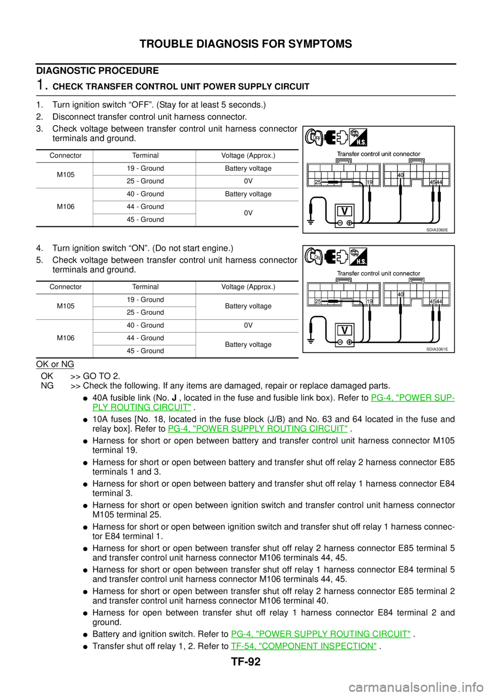
3. Check voltage between transfer control unit harness connector
terminals and ground.
4. Turn ignition switch “ON”. (Do not start engine.)
5. Check voltage between transfer control unit harness connector
terminals and ground.
OK or NG
OK >> GO TO 2.
NG >> Check the following. If any items are damaged, repair or replace damaged parts.
l40A fusible link (No.J, located in the fuse and fusible link box). Refer toPG-4, "POWER SUP-
PLY ROUTING CIRCUIT".
l10A fuses [No. 18, located in the fuse block (J/B) and No. 63 and 64 located in the fuse and
relay box]. Refer toPG-4, "
POWER SUPPLY ROUTING CIRCUIT".
lHarness for short or open between battery and transfer control unit harness connector M105
terminal 19.
lHarness for short or open between battery and transfer shut off relay 2 harness connector E85
terminals 1 and 3.
lHarness for short or open between battery and transfer shut off relay 1 harness connector E84
terminal 3.
lHarness for short or open between ignition switch and transfer control unit harness connector
M105 terminal 25.
lHarness for short or open between ignition switch and transfer shut off relay 1 harness connec-
tor E84 terminal 1.
lHarness for short or open between transfer shut off relay 2 harness connector E85 terminal 5
and transfer control unit harness connector M106 terminals 44, 45.
lHarness for short or open between transfer shut off relay 1 harness connector E84 terminal 5
and transfer control unit harness connector M106 terminals 44, 45.
lHarness for short or open between transfer shut off relay 2 harness connector E85 terminal 2
and transfer control unit harness connector M106 terminal 40.
lHarness for open between transfer shut off relay 1 harness connector E84 terminal 2 and
ground.
lBattery and ignition switch. Refer toPG-4, "POWER SUPPLY ROUTING CIRCUIT".
lTransfer shut off relay 1, 2. Refer toTF-54, "COMPONENT INSPECTION".
Connector Terminal Voltage (Approx.)
M10519 - Ground Battery voltage
25 - Ground 0V
M10640 - Ground Battery voltage
44 - Ground
0V
45 - Ground
SDIA3360E
Connector Terminal Voltage (Approx.)
M10519 - Ground
Battery voltage
25 - Ground
M10640 - Ground 0V
44 - Ground
Battery voltage
45 - Ground
SDIA3361E
Page 3060 of 3171
TROUBLE DIAGNOSIS FOR SYMPTOMS
TF-93
C
E
F
G
H
I
J
K
L
MA
B
TF
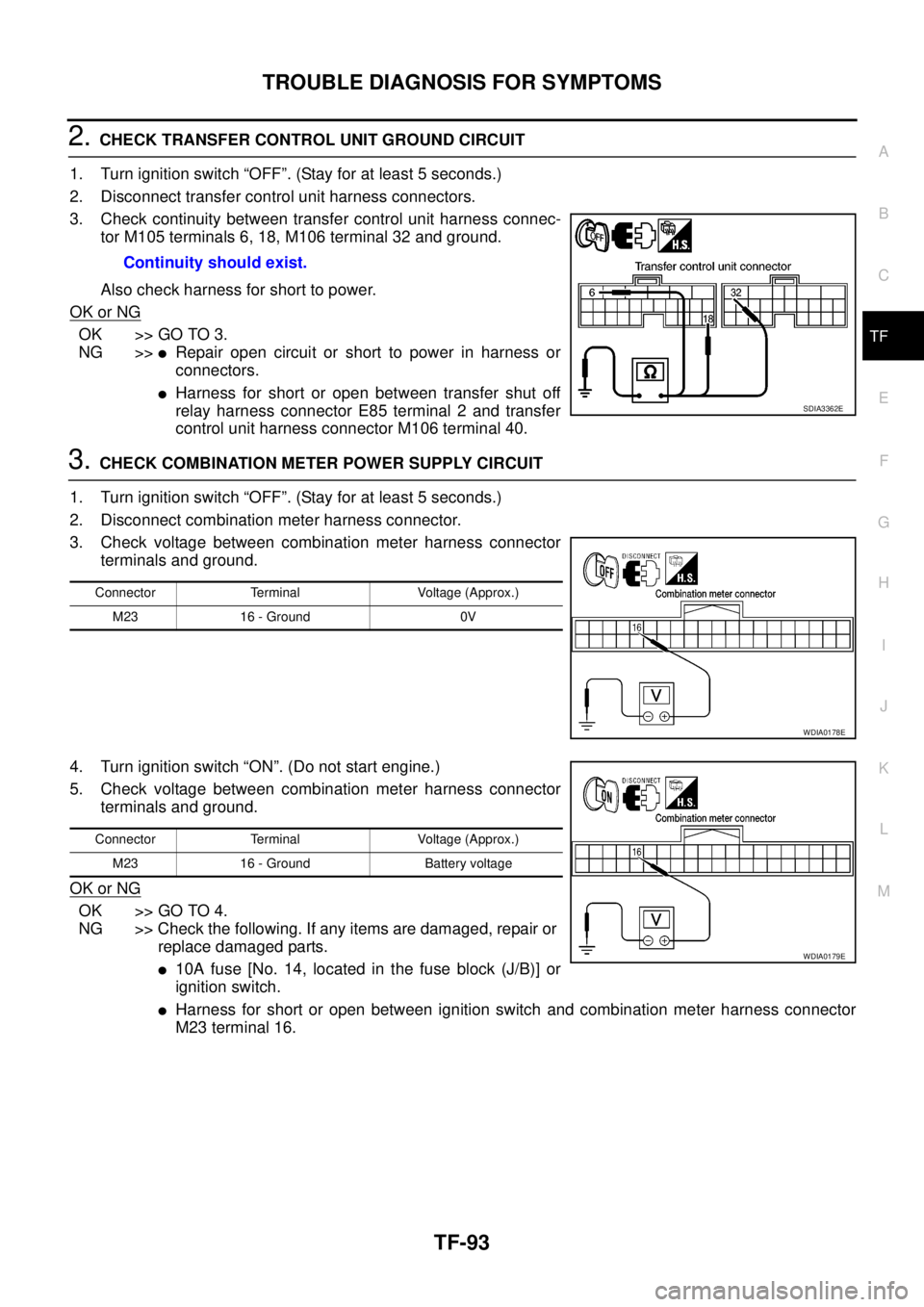
2.CHECK TRANSFER CONTROL UNIT GROUND CIRCUIT
1. Turn ignition switch “OFF”. (Stay for at least 5 seconds.)
2. Disconnect transfer control unit harness connectors.
3. Check continuity between transfer control unit harness connec-
tor M105 terminals 6, 18, M106 terminal 32 and ground.
Also check harness for short to power.
OK or NG
OK >> GO TO 3.
NG >>
lRepair open circuit or short to power in harness or
connectors.
lHarness for short or open between transfer shut off
relay harness connector E85 terminal 2 and transfer
control unit harness connector M106 terminal 40.
3.CHECK COMBINATION METER POWER SUPPLY CIRCUIT
1. Turn ignition switch “OFF”. (Stay for at least 5 seconds.)
2. Disconnect combination meter harness connector.
3. Check voltage between combination meter harness connector
terminals and ground.
4. Turn ignition switch “ON”. (Do not start engine.)
5. Check voltage between combination meter harness connector
terminals and ground.
OK or NG
OK >> GO TO 4.
NG >> Check the following. If any items are damaged, repair or
replace damaged parts.
l10A fuse [No. 14, located in the fuse block (J/B)] or
ignition switch.
lHarness for short or open between ignition switch and combination meter harness connector
M23 terminal 16. Continuity should exist.
SDIA3362E
Connector Terminal Voltage (Approx.)
M23 16 - Ground 0V
WDIA0178E
Connector Terminal Voltage (Approx.)
M23 16 - Ground Battery voltage
WDIA0179E
Page 3067 of 3171
TF-100
TRANSFER CONTROL UNIT
TRANSFER CONTROL UNIT
PFP:33084
Removal and InstallationEDS0032J
REMOVAL
1. Switch 4WD shift switch to 2WD and set transfer assembly to 2WD.
CAUTION:
When removal transfer control unit, transfer state must be at 2WD or AUTO.
2. Turn the ignition switch OFF and disconnect the battery cables.
3. Remove the lower instrument panel LH (LHD models) or lower instrument panel RH (RHD models). Refer
toIP-13, "
LOWER INSTRUMENT PANEL LH"(LHD models) orIP-13, "LOWER INSTRUMENT PANEL
LH"(RHD models).
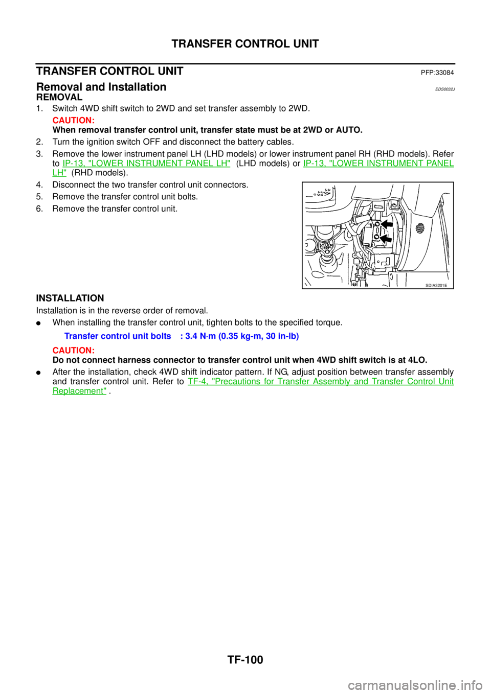
4. Disconnect the two transfer control unit connectors.
5. Remove the transfer control unit bolts.
6. Remove the transfer control unit.
INSTALLATION
Installation is in the reverse order of removal.
lWhen installing the transfer control unit, tighten bolts to the specified torque.
CAUTION:
Do not connect harness connector to transfer control unit when 4WD shift switch is at 4LO.
lAfter the installation, check 4WD shift indicator pattern. If NG, adjust position between transfer assembly
and transfer control unit. Refer toTF-4, "
Precautions for Transfer Assembly and Transfer Control Unit
Replacement".
SDIA3201E
Transfer control unit bolts : 3.4 N·m (0.35 kg-m, 30 in-lb)
Page 3115 of 3171
WW-4
FRONT WIPER AND WASHER SYSTEM
FRONT WIPER AND WASHER SYSTEM
PFP:28810
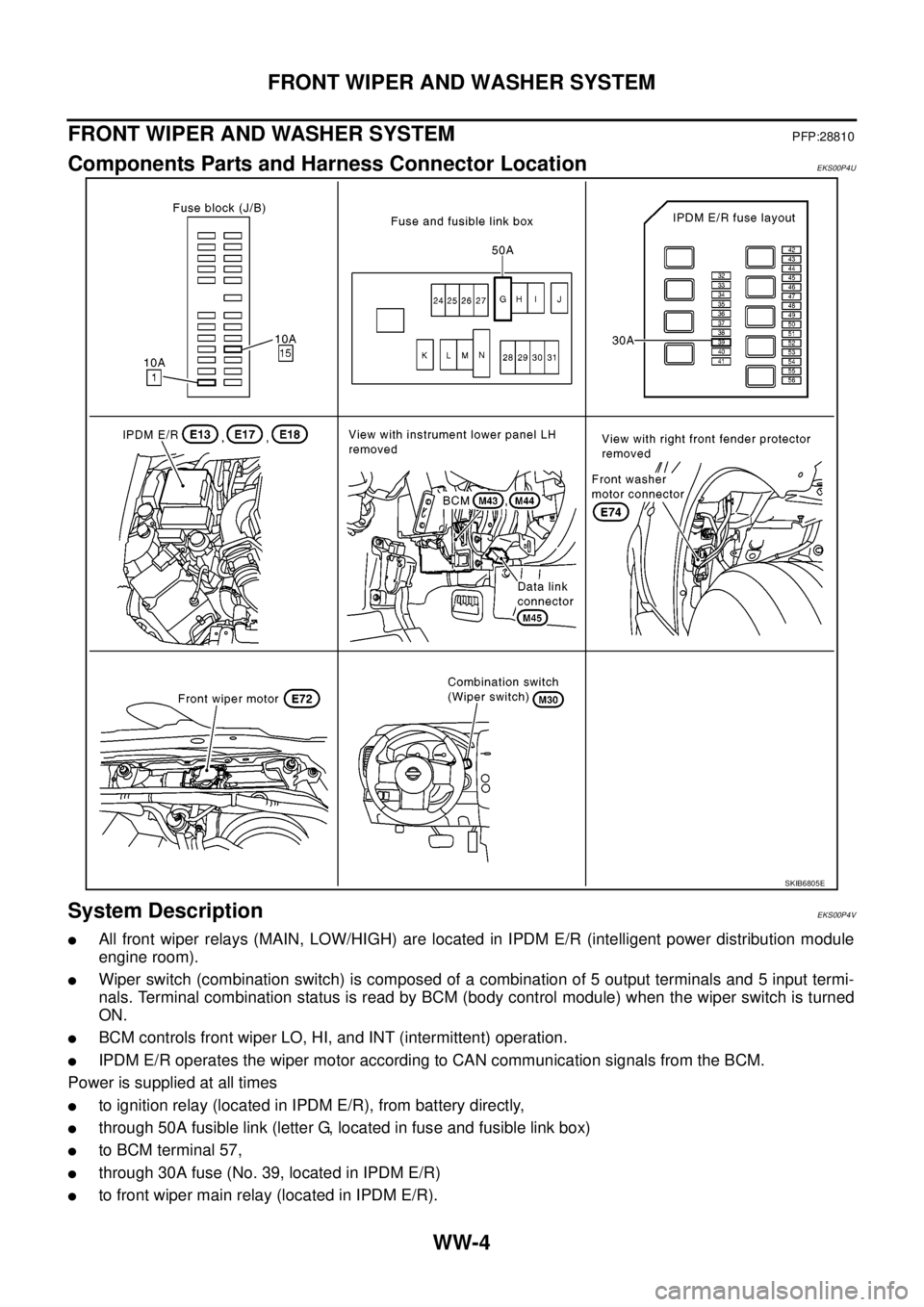
Components Parts and Harness Connector LocationEKS00P4U
System DescriptionEKS00P4V
lAll front wiper relays (MAIN, LOW/HIGH) are located in IPDM E/R (intelligent power distribution module
engine room).
lWiper switch (combination switch) is composed of a combination of 5 output terminals and 5 input termi-
nals. Terminal combination status is read by BCM (body control module) when the wiper switch is turned
ON.
lBCM controls front wiper LO, HI, and INT (intermittent) operation.
lIPDM E/R operates the wiper motor according to CAN communication signals from the BCM.
Power is supplied at all times
lto ignition relay (located in IPDM E/R), from battery directly,
lthrough 50A fusible link (letter G, located in fuse and fusible link box)
lto BCM terminal 57,
lthrough 30A fuse (No. 39, located in IPDM E/R)
lto front wiper main relay (located in IPDM E/R).
SKIB6805E
Page 3126 of 3171
FRONT WIPER AND WASHER SYSTEM
WW-15
C
D
E
F
G
H
I
J
L
MA
B
WW
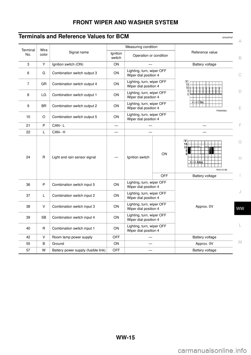
Terminals and Reference Values for BCMEKS00P4Z
Te r m i n a l
No.Wire
colorSignal nameMeasuring condition
Reference value
Ignition
switchOperation or condition
3 Y Ignition switch (ON) ON — Battery voltage
6 G Combination switch output 3 ONLighting, turn, wiper OFF
Wiper dial position 4
7 GR Combination switch output 4 ONLighting, turn, wiper OFF
Wiper dial position 4
8 LG Combination switch output 1 ONLighting, turn, wiper OFF
Wiper dial position 4
9 BR Combination switch output 2 ONLighting, turn, wiper OFF
Wiper dial position 4
10 O Combination switch output 5 ONLighting, turn, wiper OFF
Wiper dial position 4
21 P CAN-L—— —
22 L CAN-H—— —
24 R Light and rain sensor signal — Ignition switchON
OFF Battery voltage
36 P Combination switch input 5 ONLighting, turn, wiper OFF
Wiper dial position 4
Approx. 0V 37 L Combination switch input 2 ONLighting, turn, wiper OFF
Wiper dial position 4
38 V Combination switch input 3 ONLighting, turn, wiper OFF
Wiper dial position 4
39 SB Combination switch input 4 ONLighting, turn, wiper OFF
Wiper dial position 4
40 R Combination switch input 1 ONLighting, turn, wiper OFF
Wiper dial position 4
42 V Room lamp power supply OFF — Battery voltage
55 B Ground ON — Approx. 0V
57 W Battery power supply (fusible link) OFF — Battery voltage
PKIB4958J
PKIC1618E