Page 3114 of 3171

PRECAUTION
WW-3
C
D
E
F
G
H
I
J
L
MA
B
WW
PRECAUTIONPFP:00011
Precautions for Supplemental Restraint System (SRS) “AIR BAG” and “SEAT
BELT PRE-TENSIONER”
EKS00N1N
The Supplemental Restraint System such as “AIR BAG” and “SEAT BELT PRE-TENSIONER”, used along
with a front seat belt, helps to reduce the risk or severity of injury to the driver and front passenger for certain
types of collision. Information necessary to service the system safely is included in the SRS and SB section of
this Service Manual.
WARNING:
lTo avoid rendering the SRS inoperative, which could increase the risk of personal injury or death
in the event of a collision which would result in air bag inflation, all maintenance must be per-
formed by an authorized NISSAN/INFINITI dealer.
lImproper maintenance, including incorrect removal and installation of the SRS, can lead to per-
sonal injury caused by unintentional activation of the system. For removal of Spiral Cable and Air
Bag Module, see the SRS section.
lDo not use electrical test equipment on any circuit related to the SRS unless instructed to in this
Service Manual. SRS wiring harnesses can be identified by yellow and/or orange harnesses or
harness connectors.
Wiring Diagrams and Trouble DiagnosisEKS00L9V
When you read wiring diagrams, refer to the following:
lRefer toGI-15, "HowtoReadWiringDiagrams".
lRefer toPG-4, "POWER SUPPLY ROUTING CIRCUIT".
When you perform trouble diagnosis, refer to the following:
lRefer toGI-11, "How to Follow Trouble Diagnoses".
lRefer toGI-24, "How to Perform Efficient Diagnosis for an Electrical Incident".
Page 3123 of 3171
WW-12
FRONT WIPER AND WASHER SYSTEM
Wiring Diagram — WIPER —
EKS00P4Y
MKWA3673E
Page 3152 of 3171
HEADLAMP WASHER
WW-41
C
D
E
F
G
H
I
J
L
MA
B
WW
Wiring Diagram — HLC —EKS00P69
MKWA3270E
Page 3155 of 3171

WW-44
HEADLAMP WASHER
How to Proceed with Trouble Diagnosis
EKS00P6C
1. Confirm the symptoms and customer complaint.
2. Understand operation description and function description. Refer toWW-39, "
System Description".
3. Perform the Preliminary Check. Refer toWW-44, "
Preliminary Check".
4. Check symptom and repair or replace the cause of malfunction.
5. Does headlamp washer operate normally? If YES, GO TO 6. If NO, GO TO 4.
6. INSPECTION END
Preliminary CheckEKS00P6D
CHECK POWER SUPPLY AND GROUND CIRCUIT
1.CHECK FUSES OR FUSIBLE LINK
Check for blown fuses or fusible link.
Refer toWW-41, "Wiring Diagram—HLC—".
OK or NG
OK >> GO TO 2
NG >> If fuse or fusible link is blown, be sure to eliminate cause of malfunction before installing new fuse
or fusible link, Refer toPG-4, "
POWER SUPPLY ROUTING CIRCUIT".
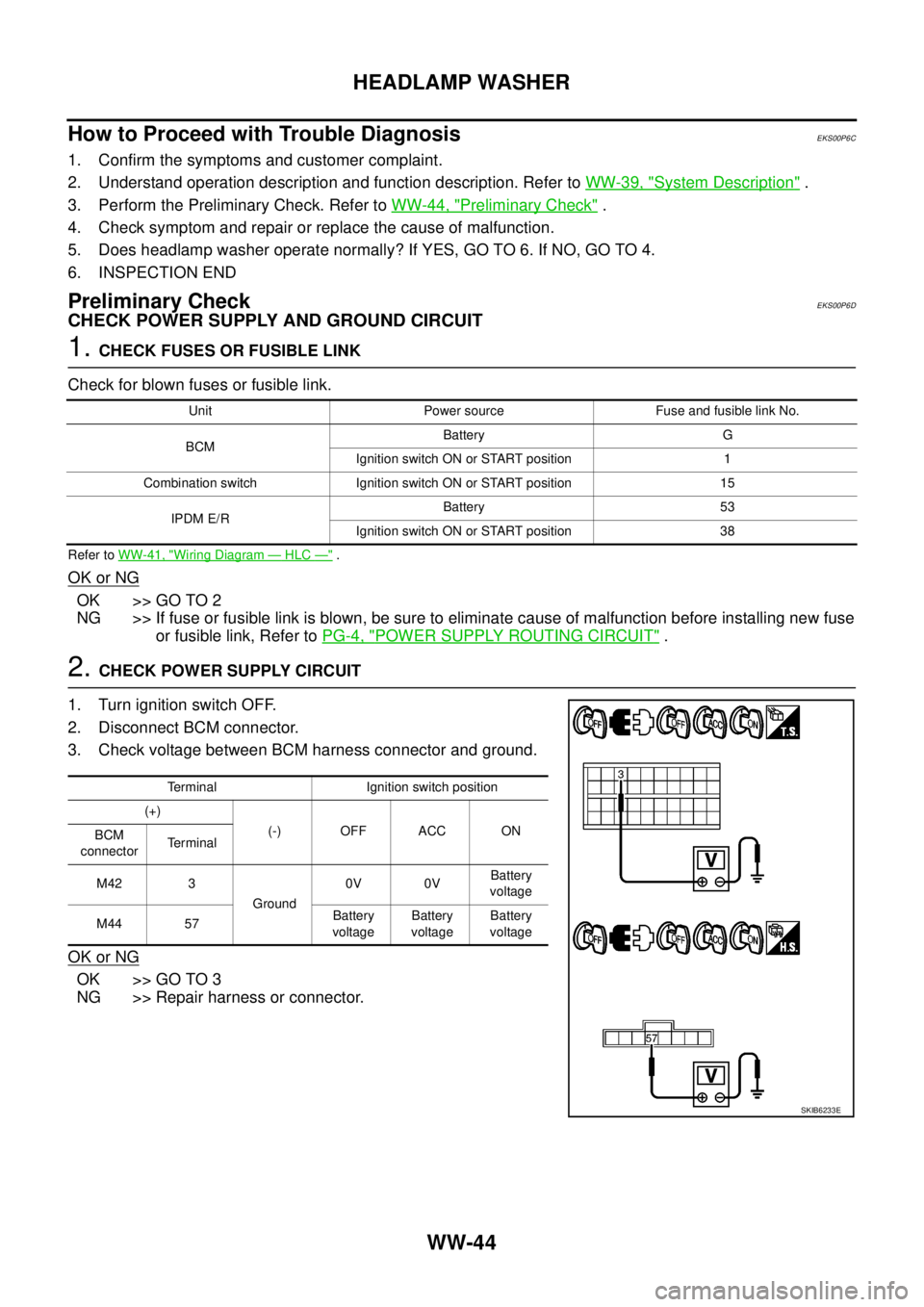
2.CHECK POWER SUPPLY CIRCUIT
1. Turn ignition switch OFF.
2. Disconnect BCM connector.
3. Check voltage between BCM harness connector and ground.
OK or NG
OK >> GO TO 3
NG >> Repair harness or connector.
Unit Power source Fuse and fusible link No.
BCMBattery G
Ignition switch ON or START position 1
Combination switch Ignition switch ON or START position 15
IPDM E/RBattery 53
Ignition switch ON or START position 38
Terminal Ignition switch position
(+)
(-) OFF ACC ON
BCM
connectorTerminal
M42 3
Ground0V 0VBattery
voltage
M44 57Battery
voltageBattery
voltageBattery
voltage
SKIB6233E
Page 3166 of 3171
CIGARETTE LIGHTER
WW-55
C
D
E
F
G
H
I
J
L
MA
B
WW
CIGARETTE LIGHTERPFP:35330
Wiring Diagram — CIGAR —EKS00P6L
MKWA2955E
Page 3168 of 3171
POWER SOCKET
WW-57
C
D
E
F
G
H
I
J
L
MA
B
WW
POWER SOCKETPFP:253A2
Wiring Diagram — P/SCKT —EKS00P6N
MKWA3597E
Page 3170 of 3171
HORN
WW-59
C
D
E
F
G
H
I
J
L
MA
B
WW
HORNPFP:25610
Wiring Diagram — HORN —EKS00P6Q
MKWA3598E