2005 NISSAN NAVARA lock
[x] Cancel search: lockPage 1637 of 3171
HOW TO USE THIS MANUAL
GI-15
C
D
E
F
G
H
I
J
K
L
MB
GI
How to Read Wiring DiagramsEAS001GY
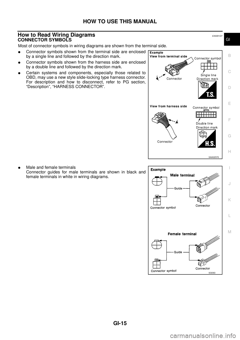
CONNECTOR SYMBOLS
Most of connector symbols in wiring diagrams are shown from the terminal side.
lConnector symbols shown from the terminal side are enclosed
by a single line and followed by the direction mark.
lConnector symbols shown from the harness side are enclosed
by a double line and followed by the direction mark.
lCertain systems and components, especially those related to
OBD, may use a new style slide-locking type harness connector.
For description and how to disconnect, refer to PG section,
“Description”, “HARNESS CONNECTOR”.
lMale and female terminals
Connector guides for male terminals are shown in black and
female terminals in white in wiring diagrams.
SAIA0257E
SGI363
Page 1649 of 3171
SERVICE INFORMATION FOR ELECTRICAL INCIDENT
GI-27
C
D
E
F
G
H
I
J
K
L
MB
GI
Cold or Hot Start Up
On some occasions an electrical incident may occur only when the car is started cold, or it may occur when
the car is restarted hot shortly after being turned off. In these cases you may have to keep the car overnight to
make a proper diagnosis.
CIRCUIT INSPECTION
Introduction
In general, testing electrical circuits is an easy task if it is approached in a logical and organized method.
Before beginning it is important to have all available information on the system to be tested. Also, get a thor-
ough understanding of system operation. Then you will be able to use the appropriate equipment and follow
the correct test procedure.
You may have to simulate vehicle vibrations while testing electrical components. Gently shake the wiring har-
ness or electrical component to do this.
NOTE:
Refer to “How to Check Terminal” to probe or check terminal.
Testing for “Opens” in the Circuit
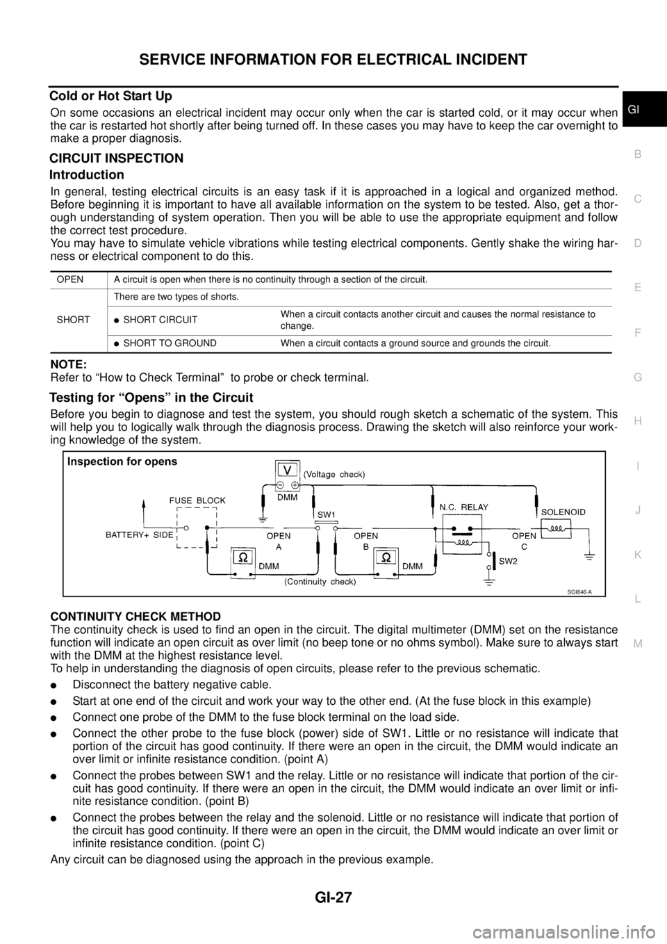
Before you begin to diagnose and test the system, you should rough sketch a schematic of the system. This
will help you to logically walk through the diagnosis process. Drawing the sketch will also reinforce your work-
ing knowledge of the system.
CONTINUITY CHECK METHOD
The continuity check is used to find an open in the circuit. The digital multimeter (DMM) set on the resistance
function will indicate an open circuit as over limit (no beep tone or no ohms symbol). Make sure to always start
with the DMM at the highest resistance level.
To help in understanding the diagnosis of open circuits, please refer to the previous schematic.
lDisconnect the battery negative cable.
lStart at one end of the circuit and work your way to the other end. (At the fuse block in this example)
lConnect one probe of the DMM to the fuse block terminal on the load side.
lConnect the other probe to the fuse block (power) side of SW1. Little or no resistance will indicate that
portion of the circuit has good continuity. If there were an open in the circuit, the DMM would indicate an
over limit or infinite resistance condition. (point A)
lConnect the probes between SW1 and the relay. Little or no resistance will indicate that portion of the cir-
cuit has good continuity. If there were an open in the circuit, the DMM would indicate an over limit or infi-
nite resistance condition. (point B)
lConnect the probes between the relay and the solenoid. Little or no resistance will indicate that portion of
the circuit has good continuity. If there were an open in the circuit, the DMM would indicate an over limit or
infinite resistance condition. (point C)
Any circuit can be diagnosed using the approach in the previous example.
OPEN A circuit is open when there is no continuity through a section of the circuit.
SHORTThere are two types of shorts.
lSHORT CIRCUITWhen a circuit contacts another circuit and causes the normal resistance to
change.
lSHORT TO GROUND When a circuit contacts a ground source and grounds the circuit.
SGI846-A
Page 1650 of 3171
GI-28
SERVICE INFORMATION FOR ELECTRICAL INCIDENT
VOLTAGE CHECK METHOD
To help in understanding the diagnosis of open circuits please refer to the previous schematic.
In any powered circuit, an open can be found by methodically checking the system for the presence of voltage.
This is done by switching the DMM to the voltage function.
lConnect one probe of the DMM to a known good ground.
lBegin probing at one end of the circuit and work your way to the other end.
lWith SW1 open, probe at SW1 to check for voltage.
voltage; open is further down the circuit than SW1.
no voltage; open is between fuse block and SW1 (point A).
lClose SW1 and probe at relay.
voltage; open is further down the circuit than the relay.
no voltage; open is between SW1 and relay (point B).
lClose the relay and probe at the solenoid.
voltage; open is further down the circuit than the solenoid.
no voltage; open is between relay and solenoid (point C).
Any powered circuit can be diagnosed using the approach in the previous example.
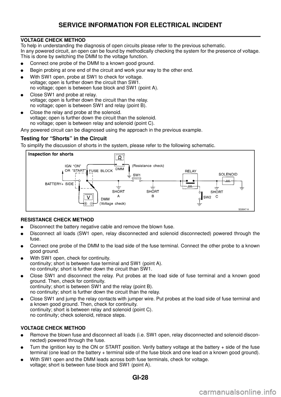
Testing for “Shorts” in the Circuit
To simplify the discussion of shorts in the system, please refer to the following schematic.
RESISTANCE CHECK METHOD
lDisconnect the battery negative cable and remove the blown fuse.
lDisconnect all loads (SW1 open, relay disconnected and solenoid disconnected) powered through the
fuse.
lConnect one probe of the DMM to the load side of the fuse terminal. Connect the other probe to a known
good ground.
lWith SW1 open, check for continuity.
continuity; short is between fuse terminal and SW1 (point A).
no continuity; short is further down the circuit than SW1.
lClose SW1 and disconnect the relay. Put probes at the load side of fuse terminal and a known good
ground. Then, check for continuity.
continuity; short is between SW1 and the relay (point B).
no continuity; short is further down the circuit than the relay.
lClose SW1 and jump the relay contacts with jumper wire. Put probes at the load side of fuse terminal and
a known good ground. Then, check for continuity.
continuity; short is between relay and solenoid (point C).
no continuity; check solenoid, retrace steps.
VOLTAGE CHECK METHOD
lRemove the blown fuse and disconnect all loads (i.e. SW1 open, relay disconnected and solenoid discon-
nected) powered through the fuse.
lTurn the ignition key to the ON or START position. Verify battery voltage at the battery + side of the fuse
terminal (one lead on the battery + terminal side of the fuse block and one lead on a known good ground).
lWith SW1 open and the DMM leads across both fuse terminals, check for voltage.
voltage; short is between fuse block and SW1 (point A).
SGI847-A
Page 1651 of 3171
SERVICE INFORMATION FOR ELECTRICAL INCIDENT
GI-29
C
D
E
F
G
H
I
J
K
L
MB
GI
no voltage; short is further down the circuit than SW1.
lWith SW1 closed, relay and solenoid disconnected and the DMM leads across both fuse terminals, check
for voltage.
voltage; short is between SW1 and the relay (point B).
no voltage; short is further down the circuit than the relay.
lWith SW1 closed, relay contacts jumped with fused jumper wire check for voltage.
voltage; short is down the circuit of the relay or between the relay and the disconnected solenoid (point C).
no voltage; retrace steps and check power to fuse block.
Ground Inspection
Ground connections are very important to the proper operation of electrical and electronic circuits. Ground
connections are often exposed to moisture, dirt and other corrosive elements. The corrosion (rust) can
become an unwanted resistance. This unwanted resistance can change the way a circuit works.
Electronically controlled circuits are very sensitive to proper grounding. A loose or corroded ground can drasti-
cally affect an electronically controlled circuit. A poor or corroded ground can easily affect the circuit. Even
when the ground connection looks clean, there can be a thin film of rust on the surface.
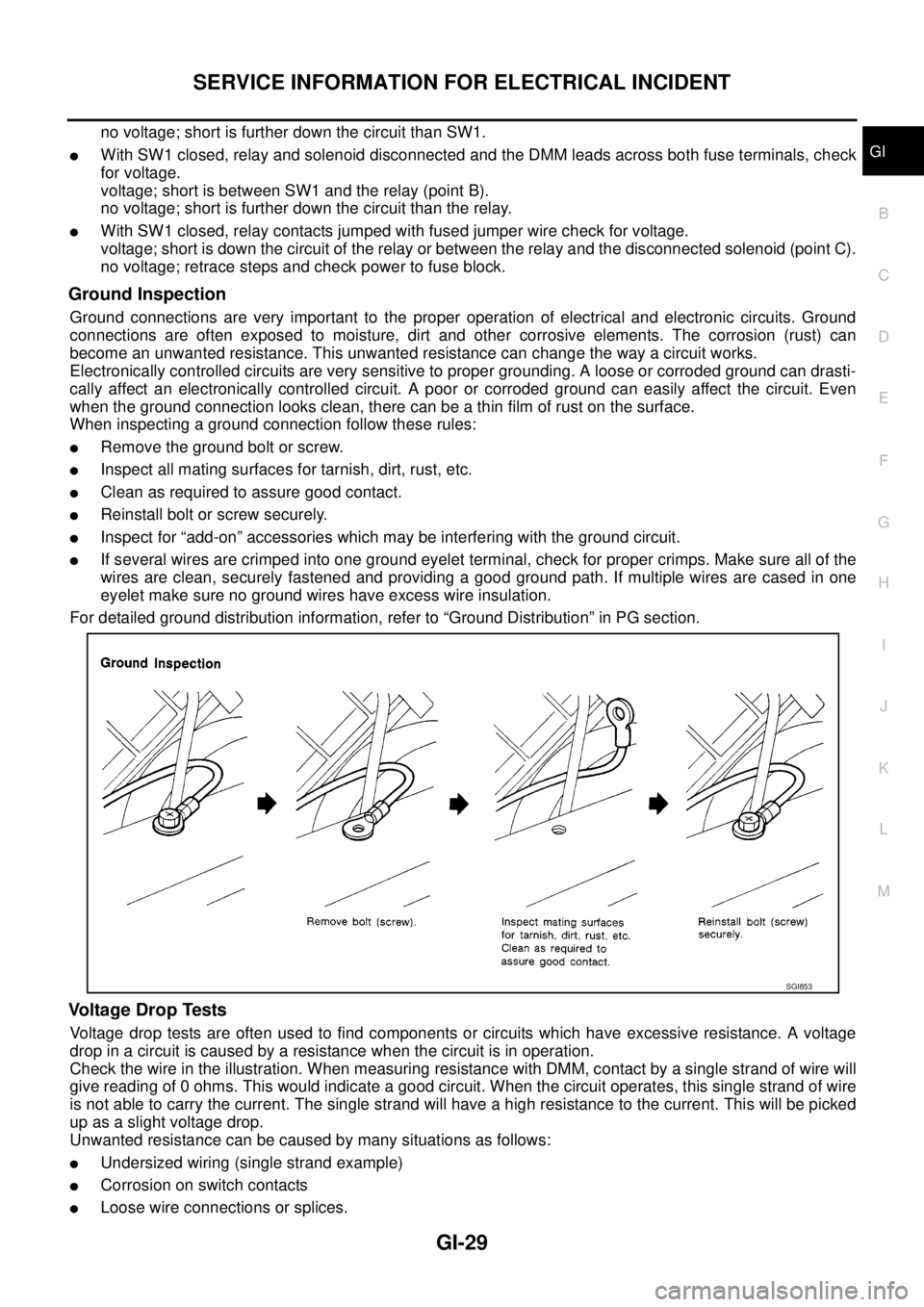
When inspecting a ground connection follow these rules:
lRemove the ground bolt or screw.
lInspect all mating surfaces for tarnish, dirt, rust, etc.
lClean as required to assure good contact.
lReinstall bolt or screw securely.
lInspect for “add-on” accessories which may be interfering with the ground circuit.
lIf several wires are crimped into one ground eyelet terminal, check for proper crimps. Make sure all of the
wires are clean, securely fastened and providing a good ground path. If multiple wires are cased in one
eyelet make sure no ground wires have excess wire insulation.
For detailed ground distribution information, refer to “Ground Distribution” in PG section.
Voltage Drop Tests
Voltage drop tests are often used to find components or circuits which have excessive resistance. A voltage
drop in a circuit is caused by a resistance when the circuit is in operation.
Check the wire in the illustration. When measuring resistance with DMM, contact by a single strand of wire will
give reading of 0 ohms. This would indicate a good circuit. When the circuit operates, this single strand of wire
is not able to carry the current. The single strand will have a high resistance to the current. This will be picked
up as a slight voltage drop.
Unwanted resistance can be caused by many situations as follows:
lUndersized wiring (single strand example)
lCorrosion on switch contacts
lLoose wire connections or splices.
SGI853
Page 1657 of 3171

CONTROL UNIT CONFIGURATION PROCEDURE
GI-35
C
D
E
F
G
H
I
J
K
L
MB
GI
´: replace unitPARTS REPLACEMENT ITEM
Work item
code
ECM BCMIntelligent Key
unitIntelligent KeySteering lock
unit
VIHCLE CONDITION
WITH NATS
WITH INTELLIGENT KEY SYSTEM
´´´´´A
´´´´—B
´´´—´A
´´´—— B
´´—´´B
´´—´—B
´´——´C
´´——— C
´—´´´D
´—´´—D
´—´—´E
´—´—— E
´——´´D
´——´—D
´———´F
´———— F
—´´´´B
—´´´—B
—´´—´B
—´´—— B
—´—´´B
—´—´—B
—´——´C
—´——— C
——´´´D
——´´—D
——´—´E
——´—— E
———´´D
———´—H
————´F
WITHOUT
INTELLIGENT
KEY SYSTEM
´´G
´—F
—´C
WITHOUT
NATS
´´I
´—J
—´K
Page 1658 of 3171

GI-36
CONTROL UNIT CONFIGURATION PROCEDURE
Work Procedure
EAS001HB
NOTE:
The configuration procedure may differ according to the replaced unit, those always use the work item code to
determinate a appropriate procedure.
Work item code Confirmation procedure Refer page
A1.“Configuration” on CONSULT-II. (At ignition switch LOCK position.)GI-37, "
Configuration (BCM)"
2. Turn ignition switch ON with mechanical key. —
3. “C/U INITIALIZATION” on CONSULT-II. CONSULT-II operation manual NATS.
4. “REGIST I-KEY ID” on CONSULT-II. CONSULT-II operation manual NATS.
B1. “Configuration” on CONSULT-II. (At ignition switch LOCK position.)GI-37, "
Configuration (BCM)"
2. “STEERING LOCK RELEASE” on CONSULT-II. CONSULT-II operation manual NATS.
3. Turn ignition switch ON with mechanical key. —
4. “C/U INITIALIZATION” on CONSULT-II. CONSULT-II operation manual NATS.
5. “REGIST I-KEY ID” on CONSULT-II. CONSULT-II operation manual NATS.
C1. “Configuration” on CONSULT-II. (At ignition switch LOCK position.)GI-37, "
Configuration (BCM)"
2. “STEERING LOCK RELEASE” on CONSULT-II. CONSULT-II operation manual NATS.
3. Turn ignition switch ON with mechanical key. —
4. “C/U INITIALIZATION” on CONSULT-II. CONSULT-II operation manual NATS.
D1. “STEERING LOCK RELEASE” on CONSULT-II. CONSULT-II operation manual NATS.
2. Turn ignition switch ON with mechanical key. —
3. “C/U INITIALIZATION” on CONSULT-II. CONSULT-II operation manual NATS.
4. “REGIST I-KEY ID” on CONSULT-II. CONSULT-II operation manual NATS.
E1. Turn ignition switch ON with mechanical key. —
2. “REGIST I-KEY ID” on CONSULT-II. CONSULT-II operation manual NATS.
F Turn ignition switch ON with mechanical key. —
G1. “Configuration” on CONSULT-II.GI-37, "
Configuration (BCM)"
2. Turn ignition switch ON with mechanical key. —
3. “C/U INITIALIZATION” on CONSULT-II. CONSULT-II operation manual NATS.
H1. “STEERING LOCK RELEASE” on CONSULT-II. CONSULT-II operation manual NATS.
2. “C/U INITIALIZATION” on CONSULT-II. CONSULT-II operation manual NATS.
3. “REGIST I-KEY ID” on CONSULT-II. CONSULT-II operation manual NATS.
J1.“Configuration” on CONSULT-II. (At ignition switch ON position.)GI-37, "
Configuration (BCM)"
2. Erase the DTC (P1612) using CONSULT-II —
I “Configuration” on CONSULT-II. (At ignition switch ON position.)GI-37, "
Configuration (BCM)"
K Turn ignition switch ON with ignition key. —
Page 1674 of 3171
GI-52
LIFTING POINT
LIFTING POINT
PFP:00000
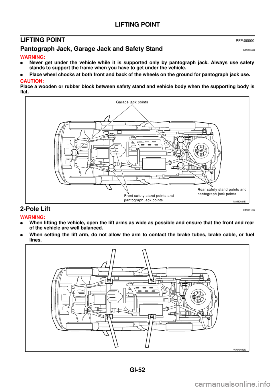
Pantograph Jack, Garage Jack and Safety StandEAS001DG
WARNING:
lNever get under the vehicle while it is supported only by pantograph jack. Always use safety
stands to support the frame when you have to get under the vehicle.
lPlace wheel chocks at both front and back of the wheels on the ground for pantograph jack use.
CAUTION:
Place a wooden or rubber block between safety stand and vehicle body when the supporting body is
flat.
2-Pole LiftEAS001DH
WARNING:
lWhen lifting the vehicle, open the lift arms as wide as possible and ensure that the front and rear
of the vehicle are well balanced.
lWhen setting the lift arm, do not allow the arm to contact the brake tubes, brake cable, or fuel
lines.
MAIB0021E
WAIA0043E
Page 1675 of 3171
TOW TRUCK TOWING
GI-53
C
D
E
F
G
H
I
J
K
L
MB
GI
TOW TRUCK TOWINGPFP:00000
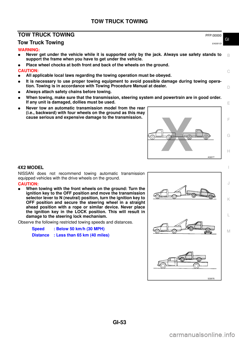
To w Tr u c k To w i n gEAS001DI
WARNING:
lNever get under the vehicle while it is supported only by the jack. Always use safety stands to
support the frame when you have to get under the vehicle.
lPlace wheel chocks at both front and back of the wheels on the ground.
CAUTION:
lAll applicable local laws regarding the towing operation must be obeyed.
lIt is necessary to use proper towing equipment to avoid possible damage during towing opera-
tion. Towing is in accordance with Towing Procedure Manual at dealer.
lAlways attach safety chains before towing.
lWhen towing, make sure that the transmission, steering system and powertrain are in good order.
If any unit is damaged, dollies must be used.
lNever tow an automatic transmission model from the rear
(i.e., backward) with four wheels on the ground as this may
cause serious and expensive damage to the transmission.
4X2 MODEL
NISSAN does not recommend towing automatic transmission
equipped vehicles with the drive wheels on the ground.
CAUTION:
lWhen towing with the front wheels on the ground: Turn the
ignition key to the OFF position and move the transmission
selector lever to N (neutral) position, turn the ignition key to
OFF position and secure the steering wheel in a straight
ahead position with a rope or similar device. Never place
the ignition key in the LOCK position. This will result in
damage to the steering lock mechanism.
Observe the following restricted towing speeds and distances.
AGI077
Speed : Below 50 km/h (30 MPH)
Distance : Less than 65 km (40 miles)
SGI976