2005 NISSAN NAVARA ignition
[x] Cancel search: ignitionPage 990 of 3171

EC-10
PRECAUTIONS
PRECAUTIONS
PFP:00001
Precautions for Supplemental Restraint System (SRS) “AIR BAG” and “SEAT
BELT PRE-TENSIONER”
EBS01KC5
The Supplemental Restraint System such as “AIR BAG” and “SEAT BELT PRE-TENSIONER”, used along
with a front seat belt, helps to reduce the risk or severity of injury to the driver and front passenger for certain
types of collision. Information necessary to service the system safely is included in the SRS and SB section of
this Service Manual.
WARNING:
lTo avoid rendering the SRS inoperative, which could increase the risk of personal injury or death
in the event of a collision which would result in air bag inflation, all maintenance must be per-
formed by an authorized NISSAN/INFINITI dealer.
lImproper maintenance, including incorrect removal and installation of the SRS, can lead to per-
sonal injury caused by unintentional activation of the system. For removal of Spiral Cable and Air
Bag Module, see the SRS section.
lDo not use electrical test equipment on any circuit related to the SRS unless instructed to in this
Service Manual. SRS wiring harnesses can be identified by yellow and/or orange harnesses or
harness connectors.
On Board Diagnostic (OBD) System of EngineEBS01KC6
The ECM has an on board diagnostic system. It will light up the malfunction indicator (MI) to warn the driver of
a malfunction causing emission deterioration.
CAUTION:
lBe sure to turn the ignition switch OFF and disconnect the battery negative cable before any
repair or inspection work. The open/short circuit of related switches, sensors, solenoid valves,
etc. will cause the MI to light up.
lBe sure to connect and lock the connectors securely after work. A loose (unlocked) connector will
cause the MI to light up due to the open circuit. (Be sure the connector is free from water, grease,
dirt, bent terminals, etc.)
lCertain systems and components, especially those related to OBD, may use a new style slide-
locking type harness connector. For description and how to disconnect, refer toPG-75, "
HAR-
NESS CONNECTOR".
lBe sure to route and secure the harnesses properly after work. The interference of the harness
with a bracket, etc. may cause the MI to light up due to the short circuit.
lBe sure to connect rubber tubes properly after work. A misconnected or disconnected rubber tube
may cause the MI to light up due to the malfunction of the fuel system, etc.
lBe sure to erase the unnecessary malfunction information (repairs completed) from the ECM
before returning the vehicle to the customer.
PrecautionsEBS01KC7
lAlways use a 12 volt battery as power source.
lDo not attempt to disconnect battery cables while engine is
running.
lBefore connecting or disconnecting the ECM harness con-
nector, turn ignition switch OFF and disconnect battery
negative cable. Failure to do so may damage the ECM
because battery voltage is applied to ECM even if ignition
switch is turned off.
lBefore removing parts, turn ignition switch OFF and then
disconnect battery negative cable.
SEF289H
Page 998 of 3171

EC-18
ENGINE CONTROL SYSTEM
System Chart
EBS01KCD
*1: The input signal is sent to the ECM through CAN communication line.
*2: The output signal is sent from the ECM through CAN communication line.
Fuel Injection Control SystemEBS01KCE
SYSTEM DESCRIPTION
Three types of fuel injection control are provided to accommodate engine operating conditions; normal control,
idle control and start control. The ECM determines the appropriate fuel injection control. Under each control,
the amount of fuel injected is adjusted to improve engine performance.
Pulse signals are sent to fuel injectors according to the input signals to adjust the amount of fuel injected to
preset value.
START CONTROL
Input/Output Signal Chart
Input (Sensor) ECM Function Output (Actuator)
lAccelerator pedal position sensor
lFuel rail pressure sensor
lFuel pump temperature sensor
lEngine coolant temperature sensor
lMass air flow sensor
lIntake air temperature sensor
lCrankshaft position sensor
lCamshaft position sensor
lTurbocharger boost sensor
lWheel sensor*1
lIgnition switch
lASCD steering switch
lASCD brake switch
lASCD clutch switch
lSt o p l a m p s w it c h
lAir conditioner switch*1
lFront air control*1
lPark/neutral position switch
lHeat up switch
lRefrigerant pressure sensor
lBattery voltageFuel injection control Fuel injector and Fuel pump
Fuel injection timing control Fuel injector and Fuel pump
Fuel cut control Fuel injector and Fuel pump
Glow control system
Glow relay and glow indicator lamp*
2
ASCD vehicle speed control Fuel injector and Fuel pump
On board diagnostic system
Malfunction indicator (MI)*
2
EGR volume control EGR volume control valve
Cooling fan control
Cooling fan relay*
2
Turbocharger boost controlTurbocharger boost control solenoid
valve
Intake air control valve controlIntake air control valve control solenoid
valve
Air conditioning cut control
Air conditioner relay*
2
Sensor Input Signal to ECM ECM Function Actuator
Engine coolant temperature sensor Engine coolant temperature
Fuel injection
control (start
control)Fuel injector
Fuel pump Crankshaft position sensor Engine speed
Camshaft position sensor Piston position
Ignition switch Start signal
Fuel rail pressure sensor Fuel rail pressure
Page 999 of 3171
ENGINE CONTROL SYSTEM
EC-19
C
D
E
F
G
H
I
J
K
L
MA
EC
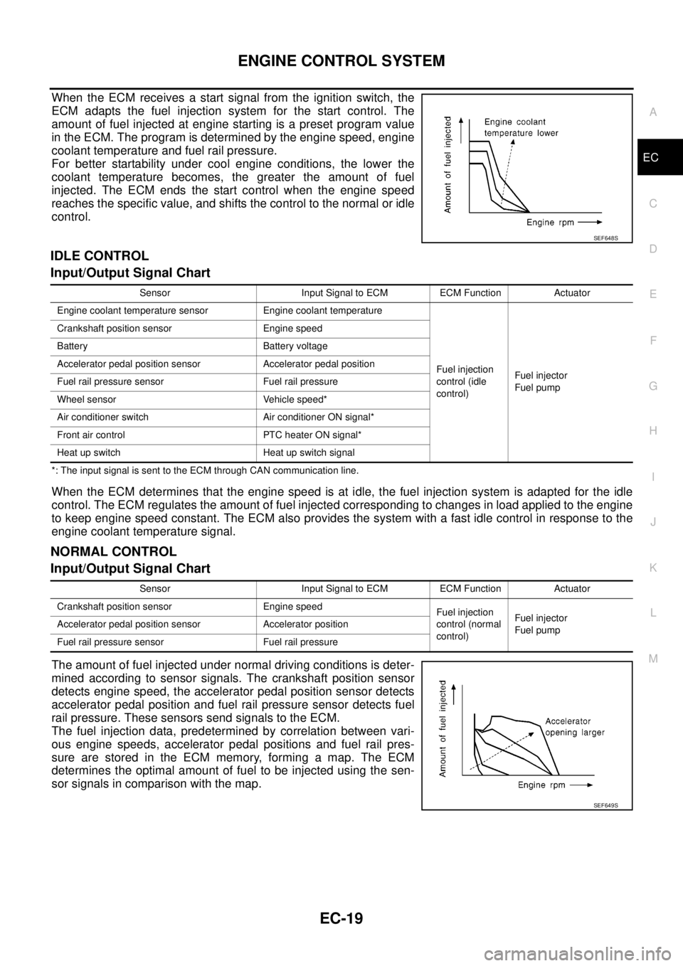
When the ECM receives a start signal from the ignition switch, the
ECM adapts the fuel injection system for the start control. The
amount of fuel injected at engine starting is a preset program value
in the ECM. The program is determined by the engine speed, engine
coolant temperature and fuel rail pressure.
For better startability under cool engine conditions, the lower the
coolant temperature becomes, the greater the amount of fuel
injected. The ECM ends the start control when the engine speed
reaches the specific value, and shifts the control to the normal or idle
control.
IDLE CONTROL
Input/Output Signal Chart
*: The input signal is sent to the ECM through CAN communication line.
When the ECM determines that the engine speed is at idle, the fuel injection system is adapted for the idle
control. The ECM regulates the amount of fuel injected corresponding to changes in load applied to the engine
to keep engine speed constant. The ECM also provides the system with a fast idle control in response to the
engine coolant temperature signal.
NORMAL CONTROL
Input/Output Signal Chart
The amount of fuel injected under normal driving conditions is deter-
mined according to sensor signals. The crankshaft position sensor
detects engine speed, the accelerator pedal position sensor detects
accelerator pedal position and fuel rail pressure sensor detects fuel
rail pressure. These sensors send signals to the ECM.
The fuel injection data, predetermined by correlation between vari-
ous engine speeds, accelerator pedal positions and fuel rail pres-
sure are stored in the ECM memory, forming a map. The ECM
determines the optimal amount of fuel to be injected using the sen-
sor signals in comparison with the map.
SEF648S
Sensor Input Signal to ECM ECM Function Actuator
Engine coolant temperature sensor Engine coolant temperature
Fuel injection
control (idle
control)Fuel injector
Fuel pump Crankshaft position sensor Engine speed
Battery Battery voltage
Accelerator pedal position sensor Accelerator pedal position
Fuel rail pressure sensor Fuel rail pressure
Wheel sensor Vehicle speed*
Air conditioner switch Air conditioner ON signal*
Front air control PTC heater ON signal*
Heat up switch Heat up switch signal
Sensor Input Signal to ECM ECM Function Actuator
Crankshaft position sensor Engine speed
Fuel injection
control (normal
control)Fuel injector
Fuel pump Accelerator pedal position sensor Accelerator position
Fuel rail pressure sensor Fuel rail pressure
SEF649S
Page 1004 of 3171
EC-24
BASIC SERVICE PROCEDURE
Fuel Pump Learning Value Clearing
EBS01KCL
DESCRIPTION
In order to always keep optimum fuel pressure in fuel rail, the ECM controls fuel pump in high precision with
monitoring the signal of fuel rail pressure sensor.
Accordingly, the ECM always learns characteristic value of fuel pump. Fuel Pump Learning Value Clearing is
an operation to clear the value of the fuel pump learning.
Fuel Pump Learning Value Clearing should be performed under the following conditions.
lFuel pump is changed.
lECM is replaced with used one which stores the fuel pump learning value of other fuel pump.
OPERATION PROCEDURE
NOTE:
When removing fuel pump, perform Fuel Pump Learning Value Clearing before starting engine.
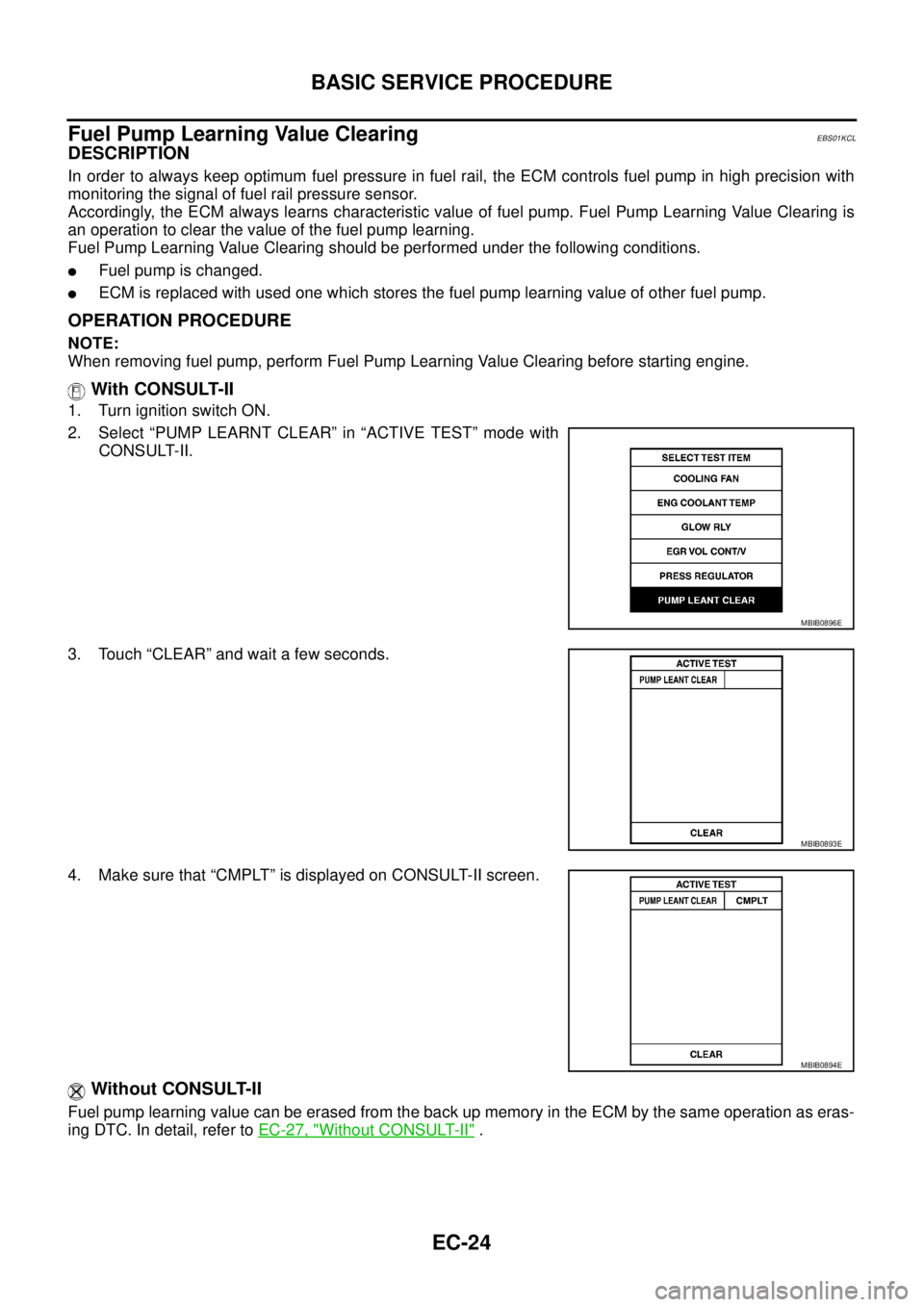
With CONSULT-II
1. Turn ignition switch ON.
2. Select “PUMP LEARNT CLEAR” in “ACTIVE TEST” mode with
CONSULT-II.
3. Touch “CLEAR” and wait a few seconds.
4. Make sure that “CMPLT” is displayed on CONSULT-II screen.
Without CONSULT-II
Fuel pump learning value can be erased from the back up memory in the ECM by the same operation as eras-
ingDTC.Indetail,refertoEC-27, "
Without CONSULT-II".
MBIB0896E
MBIB0893E
MBIB0894E
Page 1005 of 3171
BASIC SERVICE PROCEDURE
EC-25
C
D
E
F
G
H
I
J
K
L
MA
EC
Injector Adjustment Value RegistrationEBS01KCM
DESCRIPTION
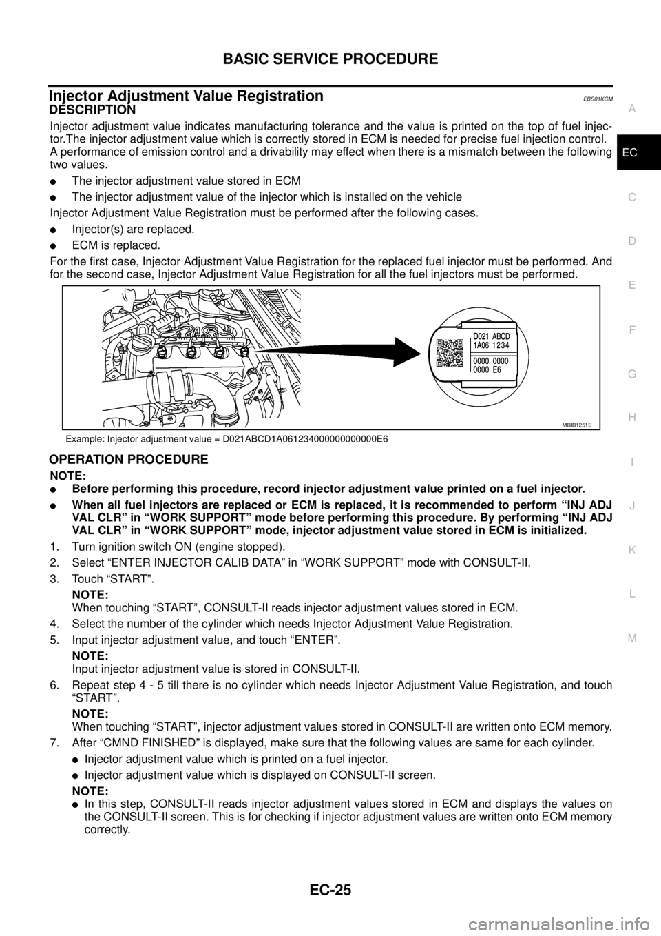
Injector adjustment value indicates manufacturing tolerance and the value is printed on the top of fuel injec-
tor.The injector adjustment value which is correctly stored in ECM is needed for precise fuel injection control.
A performance of emission control and a drivability may effect when there is a mismatch between the following
two values.
lThe injector adjustment value stored in ECM
lThe injector adjustment value of the injector which is installed on the vehicle
Injector Adjustment Value Registration must be performed after the following cases.
lInjector(s) are replaced.
lECM is replaced.
For the first case, Injector Adjustment Value Registration for the replaced fuel injector must be performed. And
for the second case, Injector Adjustment Value Registration for all the fuel injectors must be performed.
OPERATION PROCEDURE
NOTE:
lBefore performing this procedure, record injector adjustment value printed on a fuel injector.
lWhen all fuel injectors are replaced or ECM is replaced, it is recommended to perform “INJ ADJ
VAL CLR” in “WORK SUPPORT” mode before performing this procedure. By performing “INJ ADJ
VAL CLR” in “WORK SUPPORT” mode, injector adjustment value stored in ECM is initialized.
1. Turn ignition switch ON (engine stopped).
2. Select “ENTER INJECTOR CALIB DATA” in “WORK SUPPORT” mode with CONSULT-II.
3. Touch “START”.
NOTE:
When touching “START”, CONSULT-II reads injector adjustment values stored in ECM.
4. Select the number of the cylinder which needs Injector Adjustment Value Registration.
5. Input injector adjustment value, and touch “ENTER”.
NOTE:
Input injector adjustment value is stored in CONSULT-II.
6. Repeat step 4 - 5 till there is no cylinder which needs Injector Adjustment Value Registration, and touch
“START”.
NOTE:
When touching “START”, injector adjustment values stored in CONSULT-II are written onto ECM memory.
7. After “CMND FINISHED” is displayed, make sure that the following values are same for each cylinder.
lInjector adjustment value which is printed on a fuel injector.
lInjector adjustment value which is displayed on CONSULT-II screen.
NOTE:
lIn this step, CONSULT-II reads injector adjustment values stored in ECM and displays the values on
the CONSULT-II screen. This is for checking if injector adjustment values are written onto ECM memory
correctly.
Example: Injector adjustment value = D021ABCD1A061234000000000000E6
MBIB1251E
Page 1007 of 3171
ON BOARD DIAGNOSTIC (OBD) SYSTEM
EC-27
C
D
E
F
G
H
I
J
K
L
MA
EC
ON BOARD DIAGNOSTIC (OBD) SYSTEMPFP:00028
DTC Detection LogicEBS01KCN
When a malfunction is detected, the malfunction (DTC) and freeze frame data are stored in the ECM memory.
The MI will light up each time the ECM detects malfunction. For diagnostic items causing the MI to light up,
refer toEC-6, "
INDEX FOR DTC".
Diagnostic Trouble Code (DTC)EBS01KCO
HOW TO READ DTC
The DTC can be read by the following methods.
With CONSULT-II
CONSULT-IIdisplaystheDTCin"SELF-DIAGRESULTS"mode.Example:P0117,P0335,P1268,etc.These
DTCs are prescribed by ISO15031-5.
(CONSULT-II also displays the malfunctioning component or system.)
Without CONSULT-II
The number of blinks of the MI in the Diagnostic Test Mode II (Self-Diagnostic Results) indicates the DTC.
Example: 0117, 0335, 1260, etc.
lOutput of a DTC indicates a malfunction. However, the Diagnostic Test Mode II does not indicate
whether the malfunction is still occurring or has occurred in the past and has returned to normal.
CONSULT-II can identify malfunction status as shown below. Therefore, using CONSULT-II (if avail-
able) is recommended.
HOW TO ERASE DTC
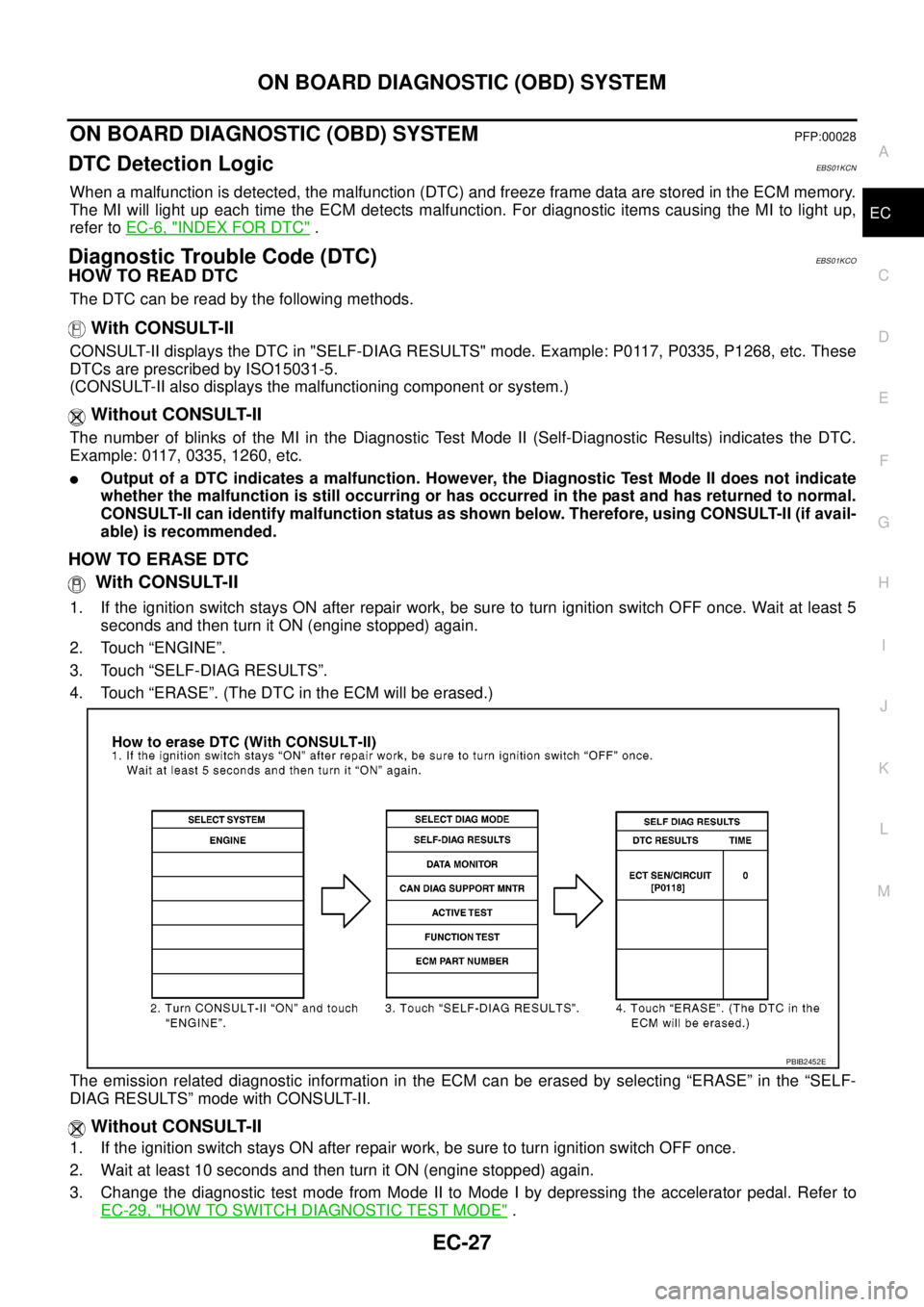
With CONSULT-II
1. If the ignition switch stays ON after repair work, be sure to turn ignition switch OFF once. Wait at least 5
seconds and then turn it ON (engine stopped) again.
2. Touch “ENGINE”.
3. Touch “SELF-DIAG RESULTS”.
4. Touch “ERASE”. (The DTC in the ECM will be erased.)
The emission related diagnostic information in the ECM can be erased by selecting “ERASE” in the “SELF-
DIAG RESULTS” mode with CONSULT-II.
Without CONSULT-II
1. If the ignition switch stays ON after repair work, be sure to turn ignition switch OFF once.
2. Wait at least 10 seconds and then turn it ON (engine stopped) again.
3. Change the diagnostic test mode from Mode II to Mode I by depressing the accelerator pedal. Refer to
EC-29, "
HOW TO SWITCH DIAGNOSTIC TEST MODE".
PBIB2452E
Page 1008 of 3171
EC-28
ON BOARD DIAGNOSTIC (OBD) SYSTEM
lIf the battery is disconnected, the emission-related diagnostic information will be lost within 24
hours.
lThe following data are cleared when the ECM memory is erased.
–Diagnostic trouble codes
–Freeze frame data
–Fuel pump learning value
Actual work procedures are explained using a DTC as an example. Be careful so that not only the DTC, but all
of the data listed above, are cleared from the ECM memory during work procedures.
Freeze Frame DataEBS01KCP
The ECM records the driving conditions such as calculated load value, engine coolant temperature, engine
speed, vehicle speed and intake manifold pressure at the moment a malfunction is detected.
The data, stored together with the DTC data, are called freeze frame data and displayed on CONSULT-II. For
details, seeEC-28, "
Freeze Frame Data".
Only one set of freeze frame data can be stored in the ECM. If freeze frame data is stored in the ECM memory
and another freeze frame data occurs later, the first (original) freeze frame data remains unchanged in the
ECM memory.
Freeze frame data (along with the DTCs) are cleared when the ECM memory is erased. Procedures for clear-
ing the ECM memory are described inEC-27, "
HOW TO ERASE DTC".
NATS (Nissan Anti-theft System)EBS01KCQ
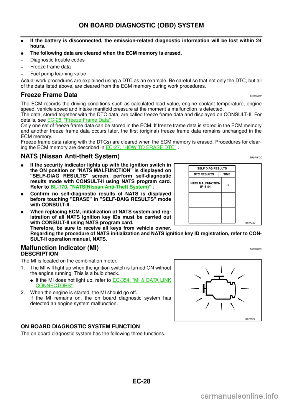
lIf the security indicator lights up with the ignition switch in
the ON position or "NATS MALFUNCTION" is displayed on
"SELF-DIAG RESULTS" screen, perform self-diagnostic
results mode with CONSULT-II using NATS program card.
Refer toBL-170, "
NATS(Nissan Anti-Theft System)".
lConfirm no self-diagnostic results of NATS is displayed
before touching "ERASE" in "SELF-DAIG RESULTS" mode
with CONSULT-II.
lWhen replacing ECM, initialization of NATS system and reg-
istration of all NATS ignition key IDs must be carried out
with CONSULT-II using NATS program card.
Therefore, be sure to receive all keys from vehicle owner.
Regarding the procedure of NATS initialization and NATS ignition key ID registration, refer to CON-
SULT-II operation manual, NATS.
Malfunction Indicator (MI)EBS01KCR
DESCRIPTION
The MI is located on the combination meter.
1. The MI will light up when the ignition switch is turned ON without
the engine running. This is a bulb check.
lIf the MI does not light up, refer toEC-354, "MI&DATA LINK
CONNECTORS".
2. When the engine is started, the MI should go off.
If the MI remains on, the on board diagnostic system has
detected an engine system malfunction.
ON BOARD DIAGNOSTIC SYSTEM FUNCTION
The on board diagnostic system has the following three functions.
SEF543X
SAT652J
Page 1009 of 3171
ON BOARD DIAGNOSTIC (OBD) SYSTEM
EC-29
C
D
E
F
G
H
I
J
K
L
MA
EC
HOWTOSWITCHDIAGNOSTICTESTMODE
NOTE:
lIt is better to count the time accurately with a clock.
lIt is impossible to switch the diagnostic mode when an accelerator pedal position sensor circuit
has a malfunction.
lAlways ECM returns to Diagnostic Test Mode I after ignition switch is turned OFF.
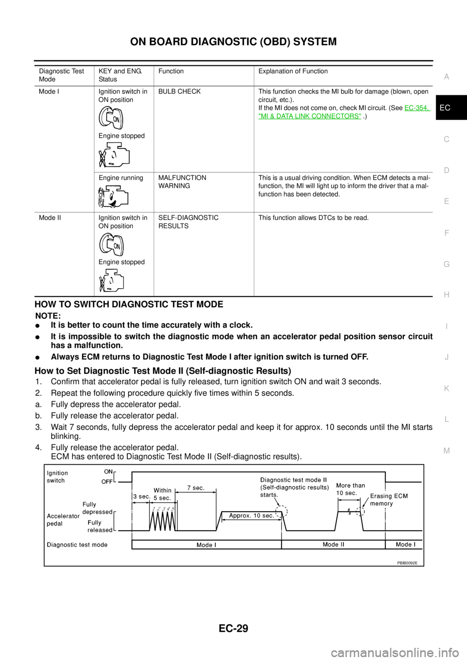
How to Set Diagnostic Test Mode II (Self-diagnostic Results)
1. Confirm that accelerator pedal is fully released, turn ignition switch ON and wait 3 seconds.
2. Repeat the following procedure quickly five times within 5 seconds.
a. Fully depress the accelerator pedal.
b. Fully release the accelerator pedal.
3. Wait 7 seconds, fully depress the accelerator pedal and keep it for approx. 10 seconds until the MI starts
blinking.
4. Fully release the accelerator pedal.
ECM has entered to Diagnostic Test Mode II (Self-diagnostic results).
Diagnostic Test
ModeKEY and ENG.
Statu sFunction Explanation of Function
Mode I Ignition switch in
ON position
Engine stoppedBULB CHECK This function checks the MI bulb for damage (blown, open
circuit, etc.).
If the MI does not come on, check MI circuit. (SeeEC-354,
"MI&DATA LINK CONNECTORS".)
Engine running MALFUNCTION
WARNINGThis is a usual driving condition. When ECM detects a mal-
function, the MI will light up to inform the driver that a mal-
function has been detected.
Mode II Ignition switch in
ON position
Engine stoppedSELF-DIAGNOSTIC
RESULTSThis function allows DTCs to be read.
PBIB0092E