2005 NISSAN NAVARA check engine light
[x] Cancel search: check engine lightPage 1183 of 3171
DTC P0563 BATTERY VOLTAGE
EC-203
C
D
E
F
G
H
I
J
K
L
MA
EC
DTC P0563 BATTERY VOLTAGEPFP:24410
On Board Diagnosis LogicEBS01KI1
The MI will not light up for this self-diagnosis.
DTC Confirmation ProcedureEBS01KI2
NOTE:
If DTC Confirmation Procedure has been previously conducted, always turn ignition switch OFF and wait at
least 10 seconds before conducting the next test.
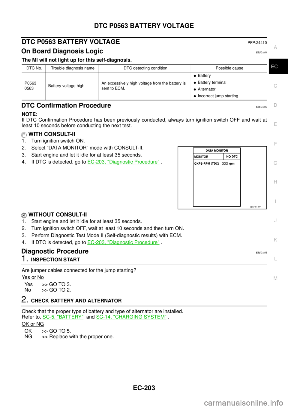
WITH CONSULT-II
1. Turn ignition switch ON.
2. Select “DATA MONITOR” mode with CONSULT-II.
3. Start engine and let it idle for at least 35 seconds.
4. If DTC is detected, go toEC-203, "
Diagnostic Procedure".
WITHOUT CONSULT-II
1. Start engine and let it idle for at least 35 seconds.
2. Turn ignition switch OFF, wait at least 10 seconds and then turn ON.
3. Perform Diagnostic Test Mode II (Self-diagnostic results) with ECM.
4. If DTC is detected, go toEC-203, "
Diagnostic Procedure".
Diagnostic ProcedureEBS01KI3
1.INSPECTION START
Are jumper cables connected for the jump starting?
Ye s o r N o
Ye s > > G O T O 3 .
No >> GO TO 2.
2.CHECK BATTERY AND ALTERNATOR
Check that the proper type of battery and type of alternator are installed.
Refer to,SC-5, "
BATTERY"andSC-14, "CHARGING SYSTEM".
OK or NG
OK >> GO TO 5.
NG >> Replace with the proper one.
DTC No. Trouble diagnosis name DTC detecting condition Possible cause
P0563
0563Battery voltage highAn excessively high voltage from the battery is
sent to ECM.
lBattery
lBattery terminal
lAlternator
lIncorrect jump starting
SEF817Y
Page 1292 of 3171
EC-312
TC BOOST CONTROL SOLENOID VALVE
Diagnostic Procedure
EBS01KM2
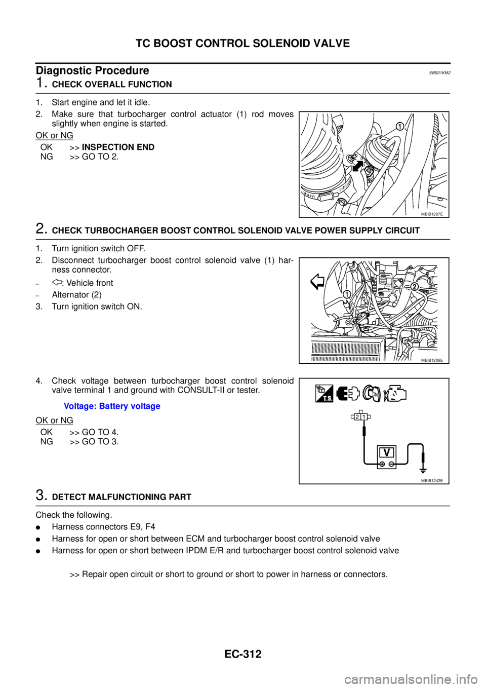
1.CHECK OVERALL FUNCTION
1. Start engine and let it idle.
2. Make sure that turbocharger control actuator (1) rod moves
slightly when engine is started.
OK or NG
OK >>INSPECTION END
NG >> GO TO 2.
2.CHECK TURBOCHARGER BOOST CONTROL SOLENOID VALVE POWER SUPPLY CIRCUIT
1. Turn ignition switch OFF.
2. Disconnect turbocharger boost control solenoid valve (1) har-
ness connector.
–: Vehicle front
–Alternator (2)
3. Turn ignition switch ON.
4. Check voltage between turbocharger boost control solenoid
valve terminal 1 and ground with CONSULT-II or tester.
OK or NG
OK >> GO TO 4.
NG >> GO TO 3.
3.DETECT MALFUNCTIONING PART
Check the following.
lHarness connectors E9, F4
lHarness for open or short between ECM and turbocharger boost control solenoid valve
lHarness for open or short between IPDM E/R and turbocharger boost control solenoid valve
>> Repair open circuit or short to ground or short to power in harness or connectors.
MBIB1207E
MBIB1206E
Voltage: Battery voltage
MBIB1242E
Page 1468 of 3171
EM-86
PRIMARY TIMING CHAIN
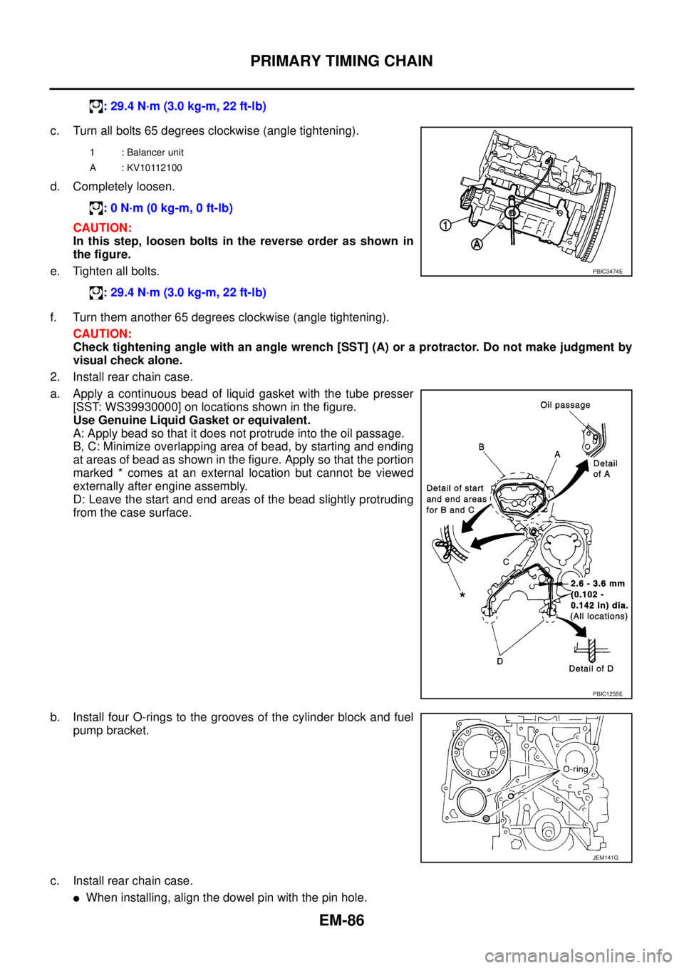
c. Turn all bolts 65 degrees clockwise (angle tightening).
d. Completely loosen.
CAUTION:
In this step, loosen bolts in the reverse order as shown in
the figure.
e. Tighten all bolts.
f. Turn them another 65 degrees clockwise (angle tightening).
CAUTION:
Check tightening angle with an angle wrench [SST] (A) or a protractor. Do not make judgment by
visual check alone.
2. Install rear chain case.
a. Apply a continuous bead of liquid gasket with the tube presser
[SST: WS39930000] on locations shown in the figure.
Use Genuine Liquid Gasket or equivalent.
A: Apply bead so that it does not protrude into the oil passage.
B, C: Minimize overlapping area of bead, by starting and ending
at areas of bead as shown in the figure. Apply so that the portion
marked * comes at an external location but cannot be viewed
externally after engine assembly.
D: Leave the start and end areas of the bead slightly protruding
from the case surface.
b. Install four O-rings to the grooves of the cylinder block and fuel
pump bracket.
c. Install rear chain case.
lWhen installing, align the dowel pin with the pin hole.: 29.4 N·m (3.0 kg-m, 22 ft-lb)
1 : Balancer unit
A : KV10112100
: 0 N·m (0 kg-m, 0 ft-lb)
: 29.4 N·m (3.0 kg-m, 22 ft-lb)
PBIC3474E
PBIC1255E
JEM141G
Page 1514 of 3171
EM-132
CYLINDER BLOCK
MAIN BEARING OIL CLEARANCE
Method by Measurement
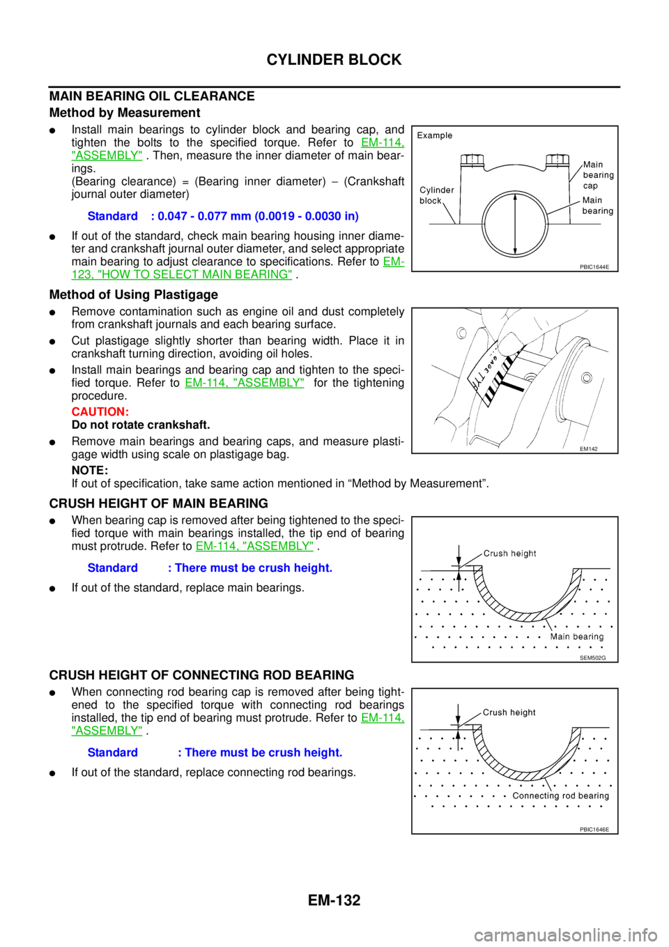
lInstall main bearings to cylinder block and bearing cap, and
tighten the bolts to the specified torque. Refer toEM-114,
"ASSEMBLY". Then, measure the inner diameter of main bear-
ings.
(Bearing clearance) = (Bearing inner diameter)-(Crankshaft
journal outer diameter)
lIf out of the standard, check main bearing housing inner diame-
ter and crankshaft journal outer diameter, and select appropriate
main bearing to adjust clearance to specifications. Refer toEM-
123, "HOW TO SELECT MAIN BEARING".
Method of Using Plastigage
lRemove contamination such as engine oil and dust completely
from crankshaft journals and each bearing surface.
lCut plastigage slightly shorter than bearing width. Place it in
crankshaft turning direction, avoiding oil holes.
lInstall main bearings and bearing cap and tighten to the speci-
fied torque. Refer toEM-114, "
ASSEMBLY"for the tightening
procedure.
CAUTION:
Do not rotate crankshaft.
lRemove main bearings and bearing caps, and measure plasti-
gage width using scale on plastigage bag.
NOTE:
If out of specification, take same action mentioned in “Method by Measurement”.
CRUSH HEIGHT OF MAIN BEARING
lWhen bearing cap is removed after being tightened to the speci-
fied torque with main bearings installed, the tip end of bearing
must protrude. Refer toEM-114, "
ASSEMBLY".
lIf out of the standard, replace main bearings.
CRUSH HEIGHT OF CONNECTING ROD BEARING
lWhen connecting rod bearing cap is removed after being tight-
ened to the specified torque with connecting rod bearings
installed, the tip end of bearing must protrude. Refer toEM-114,
"ASSEMBLY".
lIf out of the standard, replace connecting rod bearings.Standard : 0.047 - 0.077 mm (0.0019 - 0.0030 in)
PBIC1644E
EM142
Standard : There must be crush height.
SEM502G
Standard : There must be crush height.
PBIC1646E
Page 1647 of 3171
SERVICE INFORMATION FOR ELECTRICAL INCIDENT
GI-25
C
D
E
F
G
H
I
J
K
L
MB
GI
lHeat sensitive
lFreezing
lWater intrusion
lElectrical load
lCold or hot start up
Get a thorough description of the incident from the customer. It is important for simulating the conditions of the
problem.
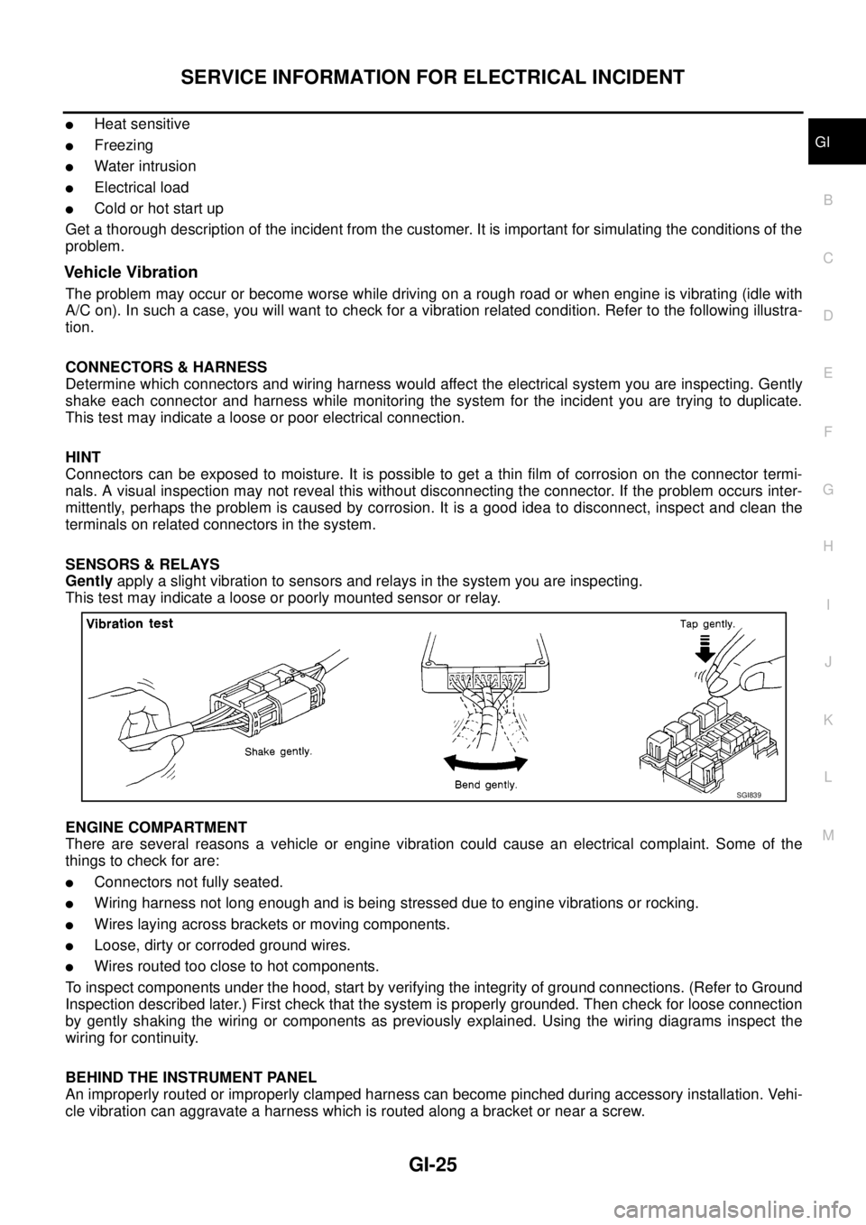
Vehicle Vibration
The problem may occur or become worse while driving on a rough road or when engine is vibrating (idle with
A/C on). In such a case, you will want to check for a vibration related condition. Refer to the following illustra-
tion.
CONNECTORS & HARNESS
Determine which connectors and wiring harness would affect the electrical system you are inspecting. Gently
shake each connector and harness while monitoring the system for the incident you are trying to duplicate.
This test may indicate a loose or poor electrical connection.
HINT
Connectors can be exposed to moisture. It is possible to get a thin film of corrosion on the connector termi-
nals. A visual inspection may not reveal this without disconnecting the connector. If the problem occurs inter-
mittently, perhaps the problem is caused by corrosion. It is a good idea to disconnect, inspect and clean the
terminals on related connectors in the system.
SENSORS & RELAYS
Gentlyapply a slight vibration to sensors and relays in the system you are inspecting.
This test may indicate a loose or poorly mounted sensor or relay.
ENGINE COMPARTMENT
There are several reasons a vehicle or engine vibration could cause an electrical complaint. Some of the
things to check for are:
lConnectors not fully seated.
lWiring harness not long enough and is being stressed due to engine vibrations or rocking.
lWires laying across brackets or moving components.
lLoose, dirty or corroded ground wires.
lWires routed too close to hot components.
To inspect components under the hood, start by verifying the integrity of ground connections. (Refer to Ground
Inspection described later.) First check that the system is properly grounded. Then check for loose connection
by gently shaking the wiring or components as previously explained. Using the wiring diagrams inspect the
wiring for continuity.
BEHIND THE INSTRUMENT PANEL
An improperly routed or improperly clamped harness can become pinched during accessory installation. Vehi-
cle vibration can aggravate a harness which is routed along a bracket or near a screw.
SGI839
Page 1671 of 3171
CONSULT-II CHECKING SYSTEM
GI-49
C
D
E
F
G
H
I
J
K
L
MB
GI
Checking EquipmentEAS001H5
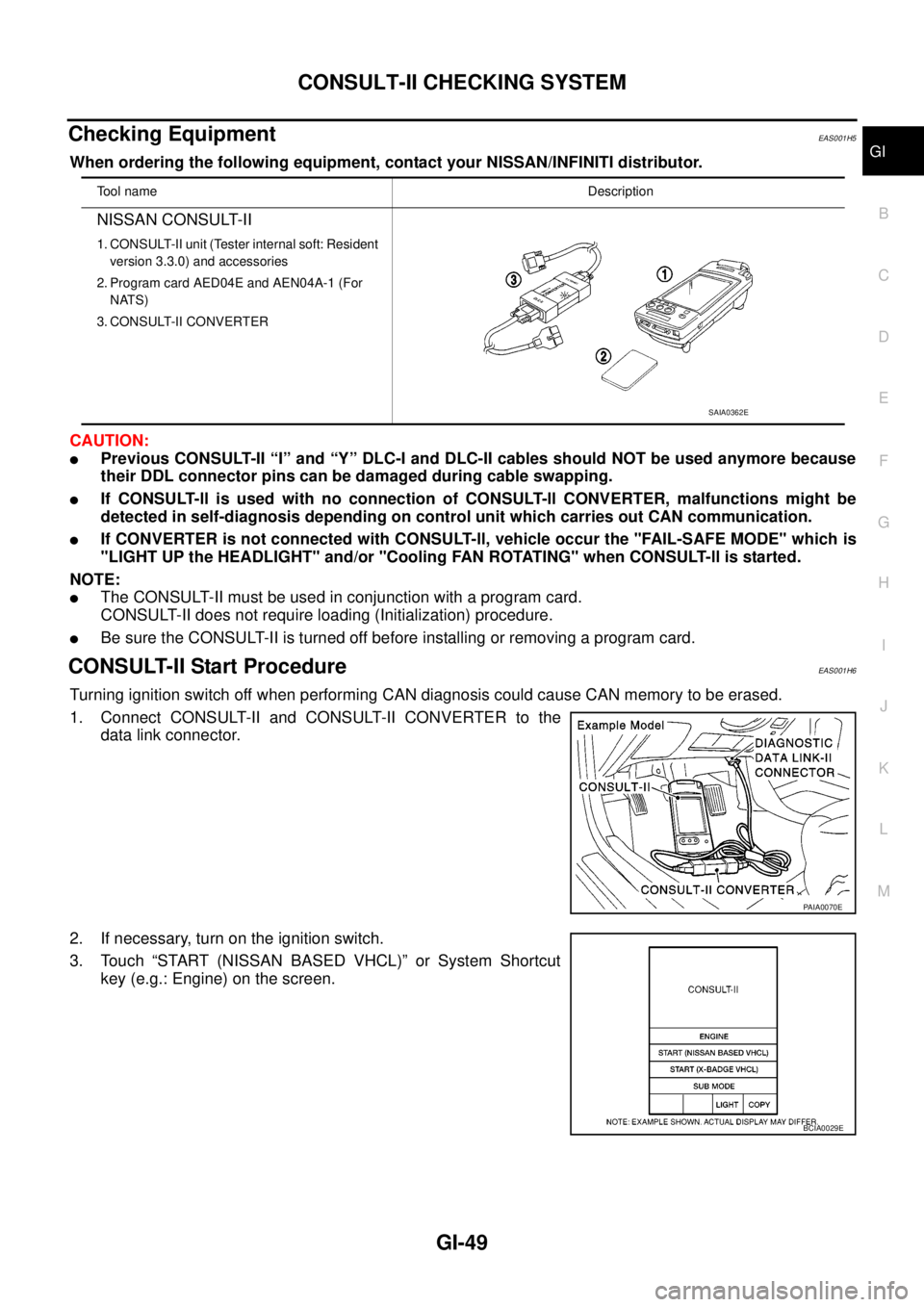
When ordering the following equipment, contact your NISSAN/INFINITI distributor.
CAUTION:
lPrevious CONSULT-II “I” and “Y” DLC-I and DLC-II cables should NOT be used anymore because
their DDL connector pins can be damaged during cable swapping.
lIf CONSULT-ll is used with no connection of CONSULT-ll CONVERTER, malfunctions might be
detected in self-diagnosis depending on control unit which carries out CAN communication.
lIf CONVERTER is not connected with CONSULT-ll, vehicle occur the "FAIL-SAFE MODE" which is
"LIGHT UP the HEADLIGHT" and/or "Cooling FAN ROTATING" when CONSULT-ll is started.
NOTE:
lThe CONSULT-II must be used in conjunction with a program card.
CONSULT-II does not require loading (Initialization) procedure.
lBe sure the CONSULT-II is turned off before installing or removing a program card.
CONSULT-II Start ProcedureEAS001H6
Turning ignition switch off when performing CAN diagnosis could cause CAN memory to be erased.
1. Connect CONSULT-II and CONSULT-II CONVERTER to the
data link connector.
2. If necessary, turn on the ignition switch.
3. Touch “START (NISSAN BASED VHCL)” or System Shortcut
key (e.g.: Engine) on the screen.
Tool nameDescription
NISSAN CONSULT-II
1. CONSULT-II unit (Tester internal soft: Resident
version 3.3.0) and accessories
2. Program card AED04E and AEN04A-1 (For
NATS)
3. CONSULT-II CONVERTER
SAIA0362E
PAIA0070E
BCIA0029E
Page 1684 of 3171

GI-62
TERMINOLOGY
Exhaust gas recirculation control-BPT
valveEGRC-BPT valve BPT valve
Exhaust gas recirculation control-solenoid
valveEGRC-solenoid valve EGR control solenoid valve
Exhaust gas recirculation temperature sen-
sor
EGRT sensor Exhaust gas temperature sensor
EGR temperature sensor
Flash electrically erasable programmable
read only memoryFEEPROM ***
Flash erasable programmable read only
memoryFEPROM ***
Flexible fuel sensor FFS ***
Flexible fuel system FF system ***
Fuel pressure regulator *** Pressure regulator
Fuel pressure regulator control solenoid
valve*** PRVR control solenoid valve
Fuel trim FT ***
Heated Oxygen sensor HO2S Exhaust gas sensor
Idle air control system IAC system Idle speed control
Idle air control valve-air regulator IACV-air regulator Air regulator
Idle air control valve-auxiliary air control
valveIACV-AAC valve Auxiliary air control (AAC) valve
Idle air control valve-FICD solenoid valve IACV-FICD solenoid valve FICD solenoid valve
Idle air control valve-idle up control sole-
noid valveIACV-idle up control solenoid valve Idle up control solenoid valve
Idle speed control-FI pot ISC-FI pot FI pot
Idle speed control system ISC system ***
Ignition control IC ***
Ignition control module ICM ***
Indirect fuel injection system IFI system ***
Intake air IA Air
Intake air temperature sensor IAT sensor Air temperature sensor
Knock *** Detonation
Knock sensor KS Detonation sensor
Malfunction indicator lamp MIL Check engine light
Manifold absolute pressure MAP ***
Manifold absolute pressure sensor MAPS ***
Manifold differential pressure MDP ***
Manifold differential pressure sensor MDPS ***
Manifold surface temperature MST ***
Manifold surface temperature sensor MSTS ***
Manifold vacuum zone MVZ ***
Manifold vacuum zone sensor MVZS ***
Mass air flow sensor MAFS Air flow meter
Mixture control solenoid valve MC solenoid valve Air-fuel ratio control solenoid valve
Multiport fuel injection System MFI system Fuel injection controlNEW TERMNEW ACRONYM /
ABBREVIATIONOLD TERM
Page 1692 of 3171
GW-6
SQUEAK AND RATTLE TROUBLE DIAGNOSES
DUPLICATE THE NOISE AND TEST DRIVE
If possible, drive the vehicle with the customer until the noise is duplicated. Note any additional information on
the Diagnostic Worksheet regarding the conditions or location of the noise. This information can be used to
duplicate the same conditions when you confirm the repair.
If the noise can be duplicated easily during the test drive, to help identify the source of the noise, try to dupli-
cate the noise with the vehicle stopped by doing one or all of the following:
1) Close a door.
2) Tap or push/pull around the area where the noise appears to be coming from.
3) Rev the engine.
4) Use a floor jack to recreate vehicle “twist”.
5) At idle, apply engine load (electrical load, half-clutch on M/T model, drive position on A/T model).
6) Raise the vehicle on a hoist and hit a tire with a rubber hammer.
lDrive the vehicle and attempt to duplicate the conditions the customer states exist when the noise occurs.
lIf it is difficult to duplicate the noise, drive the vehicle slowly on an undulating or rough road to stress the
vehicle body.
CHECK RELATED SERVICE BULLETINS
After verifying the customer concern or symptom, check ASIST for Technical Service Bulletins (TSBs) related
to that concern or symptom.
If a TSB relates to the symptom, follow the procedure to repair the noise.
LOCATE THE NOISE AND IDENTIFY THE ROOT CAUSE
1. Narrow down the noise to a general area. To help pinpoint the source of the noise, use a listening tool
(Engine Ear or mechanics stethoscope).
2. Narrowdownthenoisetoamorespecificareaandidentifythecauseofthenoiseby:
lremoving the components in the area that you suspect the noise is coming from.
Do not use too much force when removing clips and fasteners, otherwise clips and fastener can be broken
or lost during the repair, resulting in the creation of new noise.
ltapping or pushing/pulling the component that you suspect is causing the noise.
Do not tap or push/pull the component with excessive force, otherwise the noise will be eliminated only
temporarily.
lfeeling for a vibration with your hand by touching the component(s) that you suspect is (are) causing the
noise.
lplacing a piece of paper between components that you suspect are causing the noise.
llooking for loose components and contact marks.
Refer toGW-7, "
Generic Squeak and Rattle Troubleshooting".
REPAIR THE CAUSE
lIf the cause is a loose component, tighten the component securely.
lIf the cause is insufficient clearance between components:
–separate components by repositioning or loosening and retightening the component, if possible.
–insulate components with a suitable insulator such as urethane pads, foam blocks, felt cloth tape or ure-
thane tape are available through your authorized Nissan Parts Department.
CAUTION:
Do not use excessive force as many components are constructed of plastic and may be damaged.
NOTE:
Always check with the Parts Department for the latest parts information.
Each item can be ordered separately as needed.
URETHANE PADS [1.5 mm (0.059 in) thick]
Insulates connectors, harness, etc.
76268-9E005: 100´135 mm (3.94´5.31 in)/76884-71L01: 60´85 mm (2.36´3.35 in)/76884-71L02: 15´
25 mm (0.59´0.98 in)
INSULATOR (Foam blocks)
Insulates components from contact. Can be used to fill space behind a panel.
73982-9E000: 45 mm (1.77 in) thick, 50´50 mm (1.97´1.97 in)/73982-50Y00: 10 mm (0.39 in) think, 50
´50 mm (1.97´1.97 in)
INSULATOR (Light foam block)
80845-71L00: 30 mm (1.18 in) thick, 30´50 mm (1.18´1.97 in)