2005 NISSAN NAVARA check engine light
[x] Cancel search: check engine lightPage 857 of 3171
![NISSAN NAVARA 2005 Repair Workshop Manual TROUBLE DIAGNOSIS
BRC-35
[ABS]
C
D
E
G
H
I
J
K
L
MA
B
BRC
Symptom 4: ABS Function Does Not OperateEFS005UB
CAUTION:
ABS does not operate when speed is 10 km/h (6 MPH) or lower.
1.CHECK ABS WARNING LAM NISSAN NAVARA 2005 Repair Workshop Manual TROUBLE DIAGNOSIS
BRC-35
[ABS]
C
D
E
G
H
I
J
K
L
MA
B
BRC
Symptom 4: ABS Function Does Not OperateEFS005UB
CAUTION:
ABS does not operate when speed is 10 km/h (6 MPH) or lower.
1.CHECK ABS WARNING LAM](/manual-img/5/57362/w960_57362-856.png)
TROUBLE DIAGNOSIS
BRC-35
[ABS]
C
D
E
G
H
I
J
K
L
MA
B
BRC
Symptom 4: ABS Function Does Not OperateEFS005UB
CAUTION:
ABS does not operate when speed is 10 km/h (6 MPH) or lower.
1.CHECK ABS WARNING LAMP DISPLAY
Make sure that the ABS warning lamp is turned off after the ignition switch is turned ON or when driving.
OK or NG
OK >> GO TO procedure 3 “CHECK WHEEL SENSOR AND SENSOR ROTOR” of symptom1. Refer to
BRC-33, "
Symptom 1: Excessive ABS Function Operation Frequency".
NG >> Perform self-diagnosis. Refer toBRC-18, "
Self-Diagnosis".
Symptom 5: Pedal Vibration or ABS Operation Sound OccursEFS005UC
CAUTION:
Under the following conditions, ABS is activated and vibration is felt when brake pedal is lightly
depressed (just place a foot on it). However, this is normal.
lWhen shifting gears
lWhen driving on slippery road
lDuring cornering at high speed
lWhen passing over bumps or grooves [at approximately 50 mm (1.97 in) or more]
lWhen pulling away just after starting engine [at approximately 10 km/h (6 MPH) or more]
1.SYMPTOM CHECK 1
Check if there is pedal vibration or operation noise when the engine is started.
Do symptoms occur?
YES >> GO TO 2.
NO >> Perform self-diagnosis. Refer toBRC-18, "
Self-Diagnosis".
2.SYMPTOM CHECK 2
Check symptoms when electrical component (headlamps, etc.) switches are operated.
Do symptoms occur?
YES >> Check if there is a radio, antenna, antenna lead wire, or wiring close to the control unit. If there is,
move it farther away.
NO >> GO TO procedure 3²CHECK WHEEL SENSOR AND SENSOR ROTOR²of symptom 1. Refer to
BRC-33, "
Symptom 1: Excessive ABS Function Operation Frequency".
Symptom 6: ABS Warning Lamp Indication Is Not NormalEFS005UD
NOTE:
Lighting condition of ABS warning lamp refer toBRC-24, "
BASIC INSPECTION 3 ABS WARNING LAMP AND
BRAKE WARNING LAMP INSPECTION".
1.CHECK COMBINATION METER INDICATION
Check the combination meter indication and operation. Refer toDI-13, "
Self-Diagnosis Mode of Combination
Meter".
OK or NG
OK >> GO TO 2.
NG >> Combination meter is malfunctioning. Check combination meter. Refer toDI-4, "
COMBINATION
METERS".
Page 911 of 3171

DI-1
DRIVER INFORMATION SYSTEM
K ELECTRICAL
CONTENTS
C
D
E
F
G
H
I
J
L
M
SECTIONDI
A
B
DI
DRIVER INFORMATION SYSTEM
PRECAUTION ............................................................ 3
Precautions for Supplemental Restraint System
(SRS)“AIRBAG”and“SEATBELTPRE-TEN-
SIONER” .................................................................. 3
Wiring Diagrams and Trouble Diagnosis .................. 3
COMBINATION METERS ........................................... 4
System Description .................................................. 4
UNIFIED METER CONTROL UNIT ...................... 4
POWER SUPPLY AND GROUND CIRCUIT ........ 4
SPEEDOMETER ................................................... 4
TACHOMETER ..................................................... 4
WATER TEMPERATURE GAUGE ........................ 4
FUEL GAUGE ....................................................... 5
ODO/TRIP METER ............................................... 5
TRIP COMPUTER ................................................ 5
ENGINE OIL MAINTENANCE INFORMATION..... 6
METER ILLUMINATION CONTROL ..................... 6
CLOCK .................................................................. 6
AMBIENT AIR TEMPERATURE INDICATION ...... 6
Component Parts and Harness Connector Location..... 7
Arrangement of Combination Meter ......................... 8
Internal Circuit .......................................................... 9
Wiring Diagram — METER — ................................ 10
Terminals and Reference Value for Combination
Meter ...................................................................... 12
Self-Diagnosis Mode of Combination Meter ........... 13
FUNCTION .......................................................... 13
OPERATION PROCEDURE ............................... 13
TEST ITEM ......................................................... 13
CONSULT-II Function (METER) ............................. 15
CONSULT-II BASIC OPERATION ....................... 15
SELF-DIAG RESULTS ........................................ 16
DATA MONITOR ................................................. 17
Trouble Diagnosis .................................................. 18
HOW TO PERFORM TROUBLE DIAGNOSIS ... 18
PRELIMINARY CHECK ...................................... 19
Symptom Chart ...................................................... 19
Power Supply and Ground Circuit Inspection ........ 19
Vehicle Speed Signal Inspection ............................ 20
Engine Speed Signal Inspection ............................ 21Engine Coolant Temperature Signal Inspection ..... 21
Fuel Level Sensor Signal Inspection ...................... 22
Ambient Sensor Signal Inspection .......................... 24
Fuel Gauge Fluctuates, Indicates Wrong Value, or
Varies ...................................................................... 25
Fuel Gauge Does Not Move to Full position ........... 25
DTC [U1000] CAN Communication Circuit ............. 26
DTC [B2205] Vehicle Speed Circuit ........................ 26
Electrical Components Inspection .......................... 27
FUEL LEVEL SENSOR UNIT CHECK ................ 27
AMBIENT SENSOR CHECK ............................... 27
Removal and Installation of Combination Meter ..... 27
WARNING LAMPS .................................................... 28
System Description ................................................. 28
OIL PRESSURE WARNING LAMP ..................... 28
Component Parts and Harness Connector Location... 28
Schematic ............................................................... 29
Wiring Diagram — WARN — .................................. 30
A/T MODELS ....................................................... 30
M/T MODELS ...................................................... 37
Oil Pressure Warning Lamp Stays Off (Ignition
Switch ON) ............................................................. 44
Oil Pressure Warning Lamp Does Not Turn Off (Oil
Pressure Is Normal) ................................................ 45
Oil Pressure Warning Lamp Keeps Blinking (Oil
Level Is Normal) ..................................................... 46
Component Inspection ............................................ 47
OIL PRESSURE SWITCH ................................... 47
OIL LEVEL SENSOR .......................................... 47
A/T INDICATOR ........................................................ 48
System Description ................................................. 48
Wiring Diagram — AT/IND — ................................. 49
A/T Indicator Does Not Illuminate ........................... 50
WARNING CHIME ..................................................... 51
System Description ................................................. 51
POWER SUPPLY AND GROUND CIRCUIT ....... 51
LIGHT WARNING CHIME ................................... 51
KEY REMINDER WARNING CHIME .................. 51
LOW-FUEL WARNING CHIME ........................... 51
SEAT BELT WARNING CHIME ........................... 52
Page 1008 of 3171
EC-28
ON BOARD DIAGNOSTIC (OBD) SYSTEM
lIf the battery is disconnected, the emission-related diagnostic information will be lost within 24
hours.
lThe following data are cleared when the ECM memory is erased.
–Diagnostic trouble codes
–Freeze frame data
–Fuel pump learning value
Actual work procedures are explained using a DTC as an example. Be careful so that not only the DTC, but all
of the data listed above, are cleared from the ECM memory during work procedures.
Freeze Frame DataEBS01KCP
The ECM records the driving conditions such as calculated load value, engine coolant temperature, engine
speed, vehicle speed and intake manifold pressure at the moment a malfunction is detected.
The data, stored together with the DTC data, are called freeze frame data and displayed on CONSULT-II. For
details, seeEC-28, "
Freeze Frame Data".
Only one set of freeze frame data can be stored in the ECM. If freeze frame data is stored in the ECM memory
and another freeze frame data occurs later, the first (original) freeze frame data remains unchanged in the
ECM memory.
Freeze frame data (along with the DTCs) are cleared when the ECM memory is erased. Procedures for clear-
ing the ECM memory are described inEC-27, "
HOW TO ERASE DTC".
NATS (Nissan Anti-theft System)EBS01KCQ
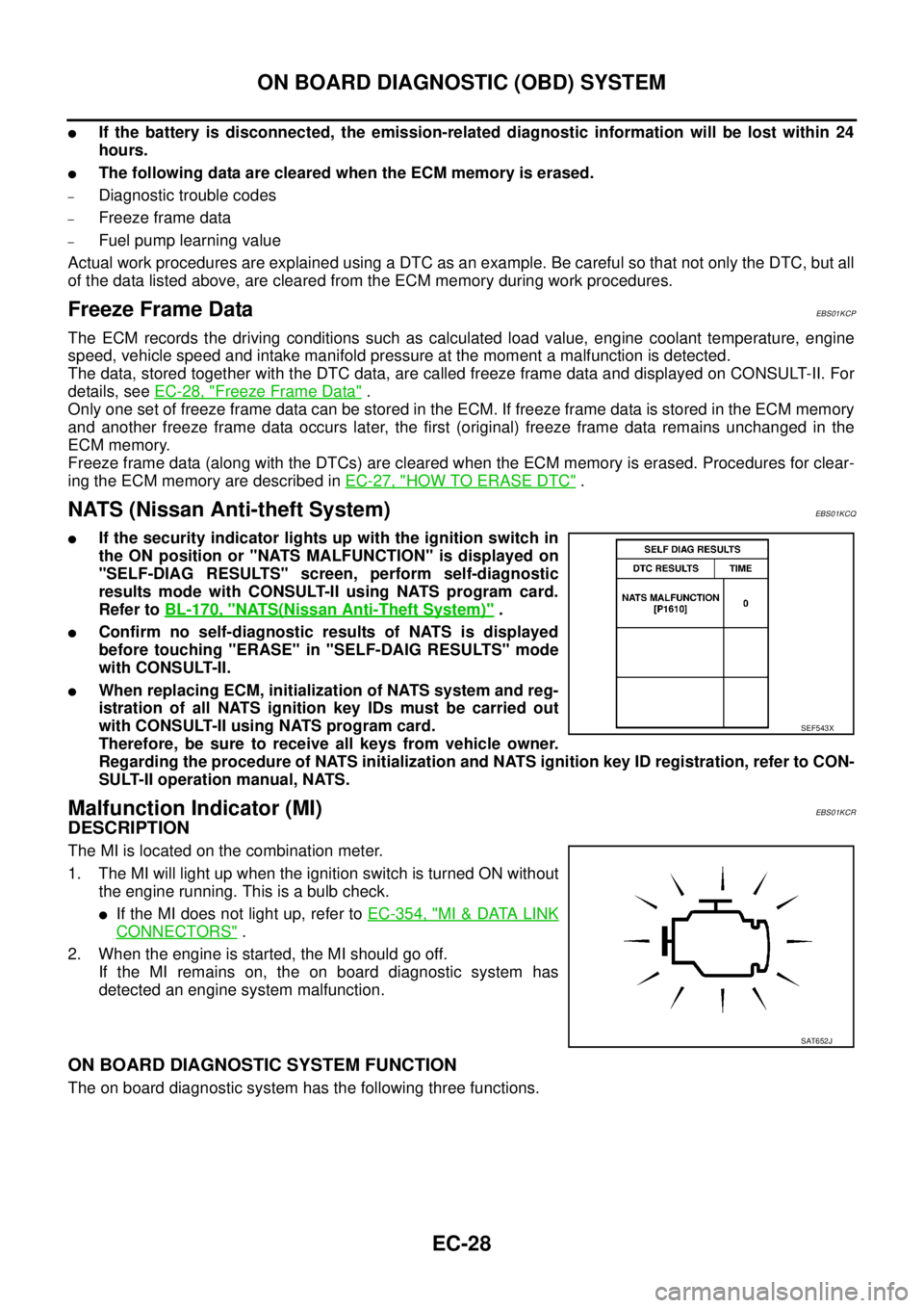
lIf the security indicator lights up with the ignition switch in
the ON position or "NATS MALFUNCTION" is displayed on
"SELF-DIAG RESULTS" screen, perform self-diagnostic
results mode with CONSULT-II using NATS program card.
Refer toBL-170, "
NATS(Nissan Anti-Theft System)".
lConfirm no self-diagnostic results of NATS is displayed
before touching "ERASE" in "SELF-DAIG RESULTS" mode
with CONSULT-II.
lWhen replacing ECM, initialization of NATS system and reg-
istration of all NATS ignition key IDs must be carried out
with CONSULT-II using NATS program card.
Therefore, be sure to receive all keys from vehicle owner.
Regarding the procedure of NATS initialization and NATS ignition key ID registration, refer to CON-
SULT-II operation manual, NATS.
Malfunction Indicator (MI)EBS01KCR
DESCRIPTION
The MI is located on the combination meter.
1. The MI will light up when the ignition switch is turned ON without
the engine running. This is a bulb check.
lIf the MI does not light up, refer toEC-354, "MI&DATA LINK
CONNECTORS".
2. When the engine is started, the MI should go off.
If the MI remains on, the on board diagnostic system has
detected an engine system malfunction.
ON BOARD DIAGNOSTIC SYSTEM FUNCTION
The on board diagnostic system has the following three functions.
SEF543X
SAT652J
Page 1009 of 3171
ON BOARD DIAGNOSTIC (OBD) SYSTEM
EC-29
C
D
E
F
G
H
I
J
K
L
MA
EC
HOWTOSWITCHDIAGNOSTICTESTMODE
NOTE:
lIt is better to count the time accurately with a clock.
lIt is impossible to switch the diagnostic mode when an accelerator pedal position sensor circuit
has a malfunction.
lAlways ECM returns to Diagnostic Test Mode I after ignition switch is turned OFF.
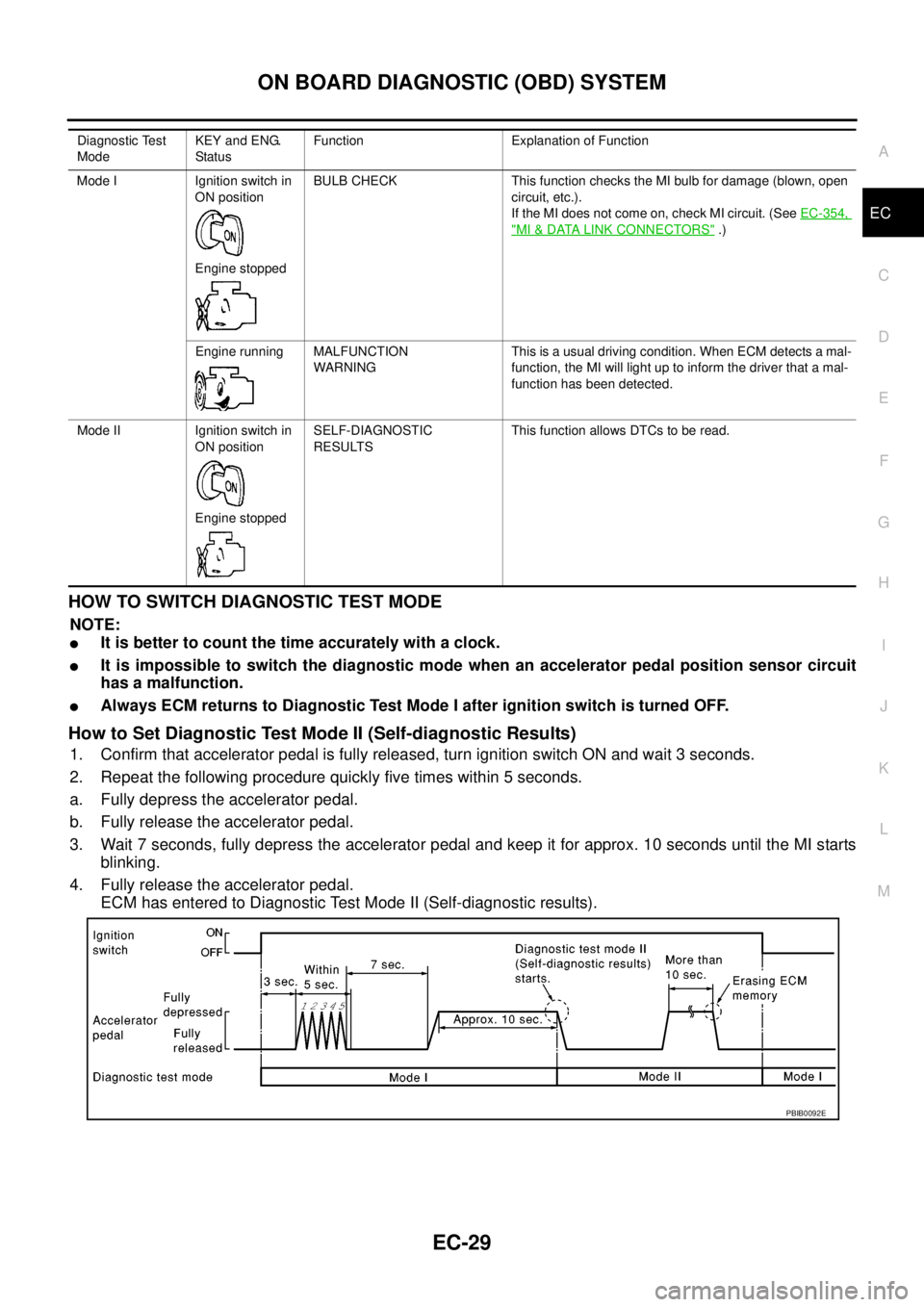
How to Set Diagnostic Test Mode II (Self-diagnostic Results)
1. Confirm that accelerator pedal is fully released, turn ignition switch ON and wait 3 seconds.
2. Repeat the following procedure quickly five times within 5 seconds.
a. Fully depress the accelerator pedal.
b. Fully release the accelerator pedal.
3. Wait 7 seconds, fully depress the accelerator pedal and keep it for approx. 10 seconds until the MI starts
blinking.
4. Fully release the accelerator pedal.
ECM has entered to Diagnostic Test Mode II (Self-diagnostic results).
Diagnostic Test
ModeKEY and ENG.
Statu sFunction Explanation of Function
Mode I Ignition switch in
ON position
Engine stoppedBULB CHECK This function checks the MI bulb for damage (blown, open
circuit, etc.).
If the MI does not come on, check MI circuit. (SeeEC-354,
"MI&DATA LINK CONNECTORS".)
Engine running MALFUNCTION
WARNINGThis is a usual driving condition. When ECM detects a mal-
function, the MI will light up to inform the driver that a mal-
function has been detected.
Mode II Ignition switch in
ON position
Engine stoppedSELF-DIAGNOSTIC
RESULTSThis function allows DTCs to be read.
PBIB0092E
Page 1018 of 3171
EC-38
TROUBLE DIAGNOSIS
Basic Inspection
EBS01KCV
Precaution:
Perform Basic Inspection without electrical or mechanical loads applied;
lHeadlamp switch is OFF.
lOn vehicles equipped with daytime light systems, set lighting switch to the 1st position to light
only small lamps.
lAir conditioner switch is OFF.
lHeater fan switch is OFF.
lRear defogger switch is OFF.
lHeat up switch is OFF.
lSteering wheel is in the straight-ahead position, etc.
1.INSPECTION START
1. Check service records for any recent repairs that may indicate a related incident.
2. Check the current need for scheduled maintenance, especially for fuel filter and air cleaner filter. Refer to
MA-8, "
PERIODIC MAINTENANCE".
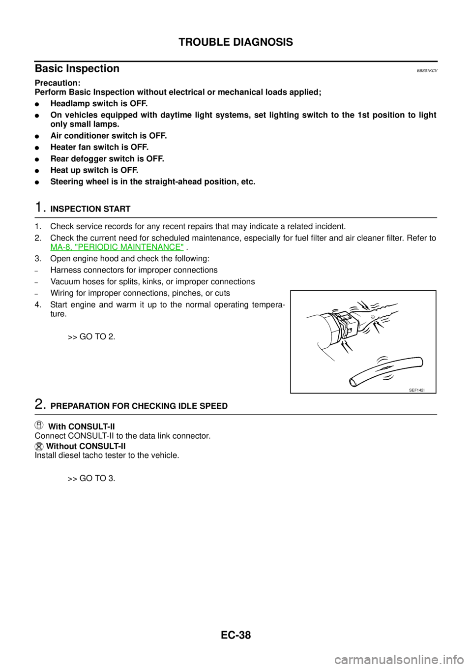
3. Open engine hood and check the following:
–Harness connectors for improper connections
–Vacuum hoses for splits, kinks, or improper connections
–Wiring for improper connections, pinches, or cuts
4. Start engine and warm it up to the normal operating tempera-
ture.
>> GO TO 2.
2.PREPARATION FOR CHECKING IDLE SPEED
With CONSULT-II
Connect CONSULT-II to the data link connector.
Without CONSULT-II
Install diesel tacho tester to the vehicle.
>> GO TO 3.
SEF142I
Page 1047 of 3171

TROUBLE DIAGNOSIS
EC-67
C
D
E
F
G
H
I
J
K
L
MA
EC
P/N POSI SWlIgnition switch: ONShift lever:
P or N (A/T), Neutral (M/T)ON
Except above OFF
START SIGNAL
lIgnition switch: ON®START®ON OFF®ON®OFF
AIRCONDSIG
lEngine: After warming up, idle
the engineAir conditioner switch: OFF OFF
Air conditioner switch: ON
(Compressor operates.)ON
BRAKE SW
lIgnition switch: ONBrake pedal: Fully released OFF
Brake pedal: Slightly depressed ON
BRAKE SW2
lIgnition switch: ON
lBrake pedal: Fully released (A/T)
lClutch pedal and brake pedal:
Fully released (M/T)OFF
lBrake pedal: Slightly depressed
(A/T)
lClutch pedal and/or brake pedal:
Slightly depressed (M/T)ON
IGN SW
lIgnition switch: ON®OFF ON®OFF
WARM UP SW
lIgnition switch: ONHeat up switch: OFF OFF
Heat up switch: ON ON
MAS AIR/FL SE*
lEngine: After warming up
lAir conditioner switch: OFF
lShift lever:
P or N (A/T), Neutral (M/T)
lNo loadIgnition switch: ON
(Engine stopped)Approximately 0.4V
Idle 1.3 - 1.7V
Engine is revving from idle to about
4,000 rpm.1.3 - 1.7V to Approximately 4.0V
(Check for liner voltage rise in
response to engine being
increased to about 4,000 rpm)
MAIN INJ WID
lEngine: After warming up
lShift lever:
P or N (A/T), Neutral (M/T)
lIdle speedNo load 0.50 - 0.70 msec
Blower fan switch: ON
Rear window defogger switch: ON0.50 - 0.80 msec
PUMP CURRENT
lEngine: After warming up
lAir conditioner switch: OFF
lShift lever:
P or N (A/T), Neutral (M/T)
lNo loadIdle 1,600 - 2,000 mA
2,000 rpm 1,500 - 1,900 mA
GLOW RLY Refer toEC-295, "
GLOW CONTROL SYSTEM".
COOLING FAN
lEngine: After warming up, idle
the engine
lAir conditioner switch: OFFEngine coolant temperature:
97°C (207°F) or lessOFF
Engine coolant temperature:
Between 98°C(208°F) and 104°C
(219°F)LOW
Engine coolant temperature:
105°C(221°F) or moreHI
EGR VOL CON/V
lEngine: After warming up
lAir conditioner switch: OFF
lShift lever:
P or N (A/T), Neutral (M/T)
lNo loadAfter 1 minute at idle More than 10 steps
Revving engine from idle to 3,200
rpm0step
INT/A VOLUME
lEngine: After warming up, idle the engine 150 - 450 mg/ MONITOR ITEM CONDITION SPECIFICATION
Page 1062 of 3171
EC-82
DTC P0016 CKP - CMP CORRELATION
DTC P0016 CKP - CMP CORRELATION
PFP:10328
On Board Diagnosis LogicEBS01KDF
The MI will not light up for this self-diagnosis.
NOTE:
If DTC P0016 is displayed with DTC P0652 or P0653, first perform the trouble diagnosis for DTC P0652
or P0653. Refer toEC-227, "
DTC P0652, P0653 SENSOR POWER SUPPLY".
DTC Confirmation ProcedureEBS01KDG
NOTE:
If DTC Confirmation Procedure has been previously conducted, always turn ignition switch OFF and wait at
least 10 seconds before conducting the next test.
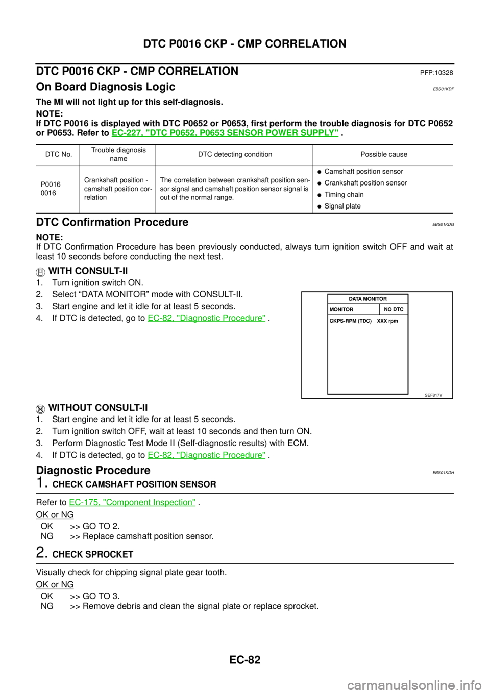
WITH CONSULT-II
1. Turn ignition switch ON.
2. Select “DATA MONITOR” mode with CONSULT-II.
3. Start engine and let it idle for at least 5 seconds.
4. If DTC is detected, go toEC-82, "
Diagnostic Procedure".
WITHOUT CONSULT-II
1. Start engine and let it idle for at least 5 seconds.
2. Turn ignition switch OFF, wait at least 10 seconds and then turn ON.
3. Perform Diagnostic Test Mode II (Self-diagnostic results) with ECM.
4. If DTC is detected, go toEC-82, "
Diagnostic Procedure".
Diagnostic ProcedureEBS01KDH
1.CHECK CAMSHAFT POSITION SENSOR
Refer toEC-175, "
Component Inspection".
OK or NG
OK >> GO TO 2.
NG >> Replace camshaft position sensor.
2.CHECK SPROCKET
Visually check for chipping signal plate gear tooth.
OK or NG
OK >> GO TO 3.
NG >> Remove debris and clean the signal plate or replace sprocket.
DTC No.Trouble diagnosis
nameDTC detecting condition Possible cause
P0016
0016Crankshaft position -
camshaft position cor-
relationThe correlation between crankshaft position sen-
sor signal and camshaft position sensor signal is
out of the normal range.
lCamshaft position sensor
lCrankshaft position sensor
lTiming chain
lSignal plate
SEF817Y
Page 1128 of 3171
EC-148
DTC P0234 TC SYSTEM
: Average voltage for pulse signal (Actual pulse signal can be confirmed by oscilloscope.)
On Board Diagnosis LogicEBS01KG4
The MI will not light up for this self-diagnosis.
NOTE:
If DTC P0234 is displayed with DTC P0652 or P0653, first perform the trouble diagnosis for DTC P0652
or P0653. Refer toEC-227, "
DTC P0652, P0653 SENSOR POWER SUPPLY".
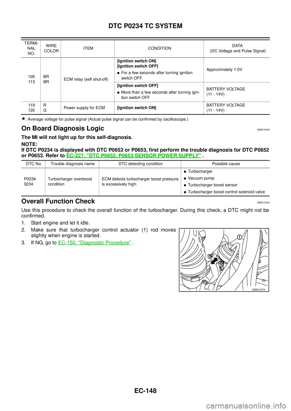
Overall Function CheckEBS01KG5
Use this procedure to check the overall function of the turbocharger. During this check, a DTC might not be
confirmed.
1. Start engine and let it idle.
2. Make sure that turbocharger control actuator (1) rod moves
slightly when engine is started.
3. If NG, go toEC-150, "
Diagnostic Procedure".
105
11 3BR
BRECM relay (self shut-off)[Ignition switch ON]
[Ignition switch OFF]lFor a few seconds after turning ignition
switch OFFApproximately 1.0V
[Ignition switch OFF]
lMore than a few seconds after turning igni-
tion switch OFFBATTERY VOLTAGE
(11 - 14V)
11 9
120R
GPower supply for ECM[Ignition switch ON]BATTERY VOLTAGE
(11 - 14V) TERMI-
NAL
NO.WIRE
COLORITEM CONDITIONDATA
(DC Voltage and Pulse Signal)
DTC No. Trouble diagnosis name DTC detecting condition Possible cause
P0234
0234Turbocharger overboost
conditionECM detects turbocharger boost pressure
is excessively high.
lTurbocharger
lVa c u u m p u m p
lTurbocharger boost sensor
lTurbocharger boost control solenoid valve
MBIB1207E