2005 NISSAN NAVARA check engine
[x] Cancel search: check enginePage 460 of 3171
ATC-126
HEATER & COOLING UNIT ASSEMBLY
Removal and Installation
EJS006C9
REMOVAL
1. Discharge the refrigerant from the A/C system. Refer toATC-138, "Discharging Refrigerant".
2. Drain the coolant from the engine cooling system. Refer toCO-8, "
DRAINING ENGINE COOLANT".
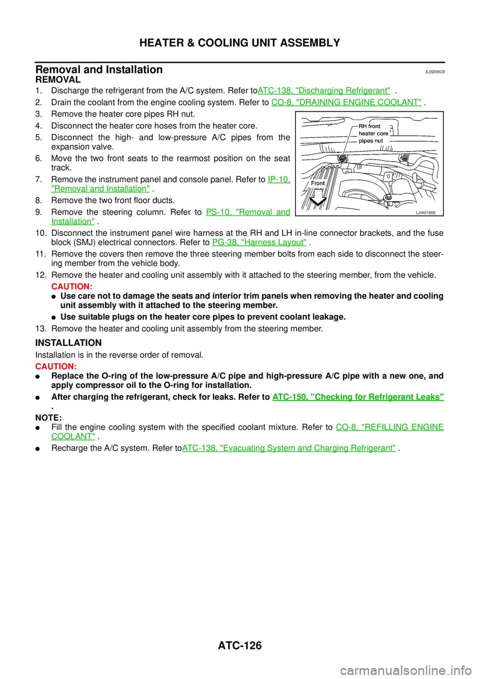
3. Remove the heater core pipes RH nut.
4. Disconnect the heater core hoses from the heater core.
5. Disconnect the high- and low-pressure A/C pipes from the
expansion valve.
6. Move the two front seats to the rearmost position on the seat
track.
7. Remove the instrument panel and console panel. Refer toIP-10,
"Removal and Installation".
8. Remove the two front floor ducts.
9. Remove the steering column. Refer toPS-10, "
Removal and
Installation".
10. Disconnect the instrument panel wire harness at the RH and LH in-line connector brackets, and the fuse
block (SMJ) electrical connectors. Refer toPG-38, "
Harness Layout".
11. Remove the covers then remove the three steering member bolts from each side to disconnect the steer-
ing member from the vehicle body.
12. Remove the heater and cooling unit assembly with it attached to the steering member, from the vehicle.
CAUTION:
lUse care not to damage the seats and interior trim panels when removing the heater and cooling
unit assembly with it attached to the steering member.
lUse suitable plugs on the heater core pipes to prevent coolant leakage.
13. Remove the heater and cooling unit assembly from the steering member.
INSTALLATION
Installation is in the reverse order of removal.
CAUTION:
lReplace the O-ring of the low-pressure A/C pipe and high-pressure A/C pipe with a new one, and
apply compressor oil to the O-ring for installation.
lAfter charging the refrigerant, check for leaks. Refer toATC-150, "Checking for Refrigerant Leaks"
.
NOTE:
lFill the engine cooling system with the specified coolant mixture. Refer toCO-8, "REFILLING ENGINE
COOLANT".
lRecharge the A/C system. Refer toATC-138, "Evacuating System and Charging Refrigerant".
LJIA0165E
Page 476 of 3171
ATC-142
REFRIGERANT LINES
Removal and Installation for Compressor
EJS006CN
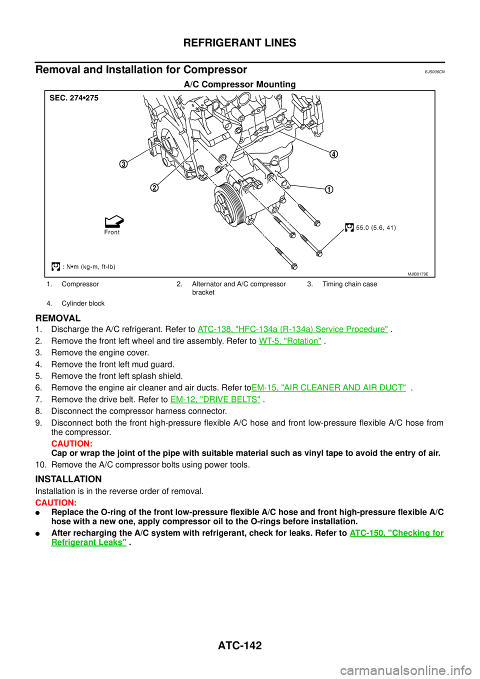
A/C Compressor Mounting
REMOVAL
1. Discharge the A/C refrigerant. Refer toATC-138, "HFC-134a (R-134a) Service Procedure".
2. Remove the front left wheel and tire assembly. Refer toWT-5, "
Rotation".
3. Remove the engine cover.
4. Remove the front left mud guard.
5. Remove the front left splash shield.
6. Remove the engine air cleaner and air ducts. Refer toEM-15, "
AIR CLEANER AND AIR DUCT".
7. Remove the drive belt. Refer toEM-12, "
DRIVE BELTS".
8. Disconnect the compressor harness connector.
9. Disconnect both the front high-pressure flexible A/C hose and front low-pressure flexible A/C hose from
the compressor.
CAUTION:
Cap or wrap the joint of the pipe with suitable material such as vinyl tape to avoid the entry of air.
10. Remove the A/C compressor bolts using power tools.
INSTALLATION
Installation is in the reverse order of removal.
CAUTION:
lReplace the O-ring of the front low-pressure flexible A/C hose and front high-pressure flexible A/C
hose with a new one, apply compressor oil to the O-rings before installation.
lAfter recharging the A/C system with refrigerant, check for leaks. Refer toATC-150, "Checking for
Refrigerant Leaks".
MJIB0179E
1. Compressor 2. Alternator and A/C compressor
bracket3. Timing chain case
4. Cylinder block
Page 479 of 3171
REFRIGERANT LINES
ATC-145
C
D
E
F
G
H
I
K
L
MA
B
AT C
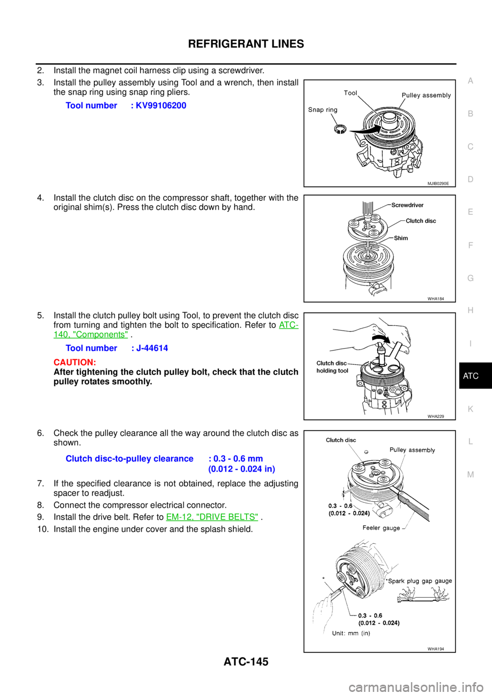
2. Install the magnet coil harness clip using a screwdriver.
3. Install the pulley assembly using Tool and a wrench, then install
the snap ring using snap ring pliers.
4. Install the clutch disc on the compressor shaft, together with the
original shim(s). Press the clutch disc down by hand.
5. Install the clutch pulley bolt using Tool, to prevent the clutch disc
from turning and tighten the bolt to specification. Refer toAT C -
140, "Components".
CAUTION:
After tightening the clutch pulley bolt, check that the clutch
pulley rotates smoothly.
6. Check the pulley clearance all the way around the clutch disc as
shown.
7. If the specified clearance is not obtained, replace the adjusting
spacer to readjust.
8. Connect the compressor electrical connector.
9. Install the drive belt. Refer toEM-12, "
DRIVE BELTS".
10. Install the engine under cover and the splash shield.Tool number : KV99106200
MJIB0290E
WHA184
Tool number : J-44614
WHA229
Clutch disc-to-pulley clearance : 0.3 - 0.6 mm
(0.012 - 0.024 in)
WHA194
Page 485 of 3171
REFRIGERANT LINES
ATC-151
C
D
E
F
G
H
I
K
L
MA
B
AT C
Dye InjectionEJS006D3
(This procedure is only necessary when recharging the system or when the compressor has seized and was
replaced.)
1. Check A/C system static (at rest) pressure. Pressure must be at least 345 kPa (3.45 bar, 3.52 kg/cm
2,50
psi).
2. Pour one bottle (1/4 ounce / 7.4 cc) of the A/C refrigerant dye into the injector tool [SST: J-41459].
3. Connect the injector tool to the A/C Low-pressure side service fitting.
4. Start engine and switch A/C ON.
5. When the A/C operating (compressor running), inject one bottle (1/4 ounce / 7.4 cc) of fluorescent dye
through the low-pressure service valve using dye injector tool J-41459 (refer to the manufacture’s operat-
ing instructions).
6. With the engine still running, disconnect the injector tool from the service fitting.
CAUTION:
Be careful the A/C system or replacing a component, pour the dye directly into the open system
connection and proceed with the service procedures.
7. Operate the A/C system for a minimum of 20 minutes to mix the dye with the system oil. Depending on the
leak size, operating conditions and location of the leak, it may take from minutes to days for the dye to
penetrate a leak and become visible.
Electronic Refrigerant Leak DetectorEJS006D4
PRECAUTIONS FOR HANDLING LEAK DETECTOR
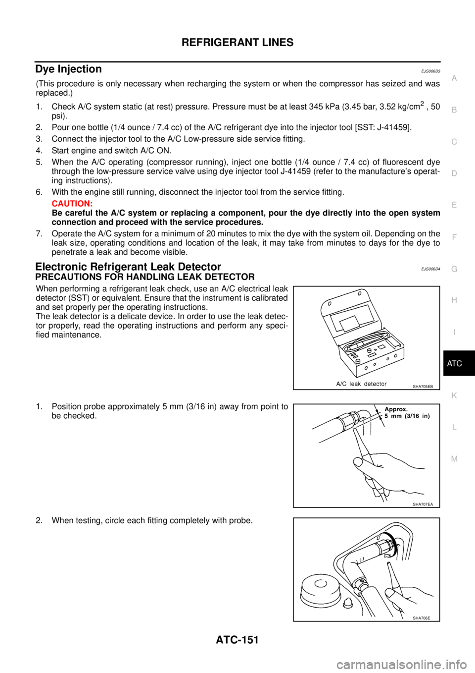
When performing a refrigerant leak check, use an A/C electrical leak
detector (SST) or equivalent. Ensure that the instrument is calibrated
and set properly per the operating instructions.
The leak detector is a delicate device. In order to use the leak detec-
tor properly, read the operating instructions and perform any speci-
fied maintenance.
1. Position probe approximately 5 mm (3/16 in) away from point to
be checked.
2. When testing, circle each fitting completely with probe.
SHA705EB
SHA707EA
SHA706E
Page 486 of 3171
ATC-152
REFRIGERANT LINES
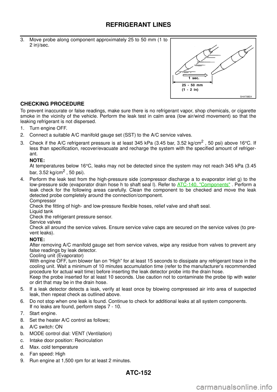
3. Move probe along component approximately 25 to 50 mm (1 to
2 in)/sec.
CHECKING PROCEDURE
To prevent inaccurate or false readings, make sure there is no refrigerant vapor, shop chemicals, or cigarette
smoke in the vicinity of the vehicle. Perform the leak test in calm area (low air/wind movement) so that the
leaking refrigerant is not dispersed.
1. Turn engine OFF.
2. Connect a suitable A/C manifold gauge set (SST) to the A/C service valves.
3. Check if the A/C refrigerant pressure is at least 345 kPa (3.45 bar, 3.52 kg/cm
2,50psi)above16°C. If
less than specification, recover/evacuate and recharge the system with the specified amount of refriger-
ant.
NOTE:
At temperatures below 16°C, leaks may not be detected since the system may not reach 345 kPa (3.45
bar, 3.52 kg/cm
2,50psi).
4. Perform the leak test from the high-pressure side (compressor discharge a to evaporator inlet g) to the
low-pressure side (evaporator drain hose h to shaft seal l). Refer toATC-140, "
Components". Perform a
leak check for the following areas carefully. Clean the component to be checked and move the leak
detected probe completely around the connection/component.
Compressor
Check the fitting of high- and low-pressure flexible hoses, relief valve and shaft seal.
Liquid tank
Check the refrigerant pressure sensor.
Service valves
Check all around the service valves. Ensure service valve caps are secured on the service valves (to pre-
vent leaks).
NOTE:
After removing A/C manifold gauge set from service valves, wipe any residue from valves to prevent any
false readings by leak detector.
Cooling unit (Evaporator)
With engine OFF, turn blower fan on “High” for at least 15 seconds to dissipate any refrigerant trace in the
cooling unit. Wait a minimum of 10 minutes accumulation time (refer to the manufacturer’s recommended
procedure for actual wait time) before inserting the leak detector probe into the drain hose.
Keep the probe inserted for at least 10 seconds. Use caution not to contaminate the probe tip with water
or dirt that may be in the drain hose.
5. If a leak detector detects a leak, verify at least once by blowing compressed air into area of suspected
leak, then repeat check as outlined above.
6. Do not stop when one leak is found. Continue to check for additional leaks at all system components.
If no leaks are found, perform steps 7 - 10.
7. Start engine.
8. Set the heater A/C control as follows;
a. A/C switch: ON
b. MODE control dial: VENT (Ventilation)
c. Intake door position: Recirculation
d. Max. cold temperature
e. Fan speed: High
9. Run engine at 1,500 rpm for at least 2 minutes.
SHA708EA
Page 487 of 3171
REFRIGERANT LINES
ATC-153
C
D
E
F
G
H
I
K
L
MA
B
AT C
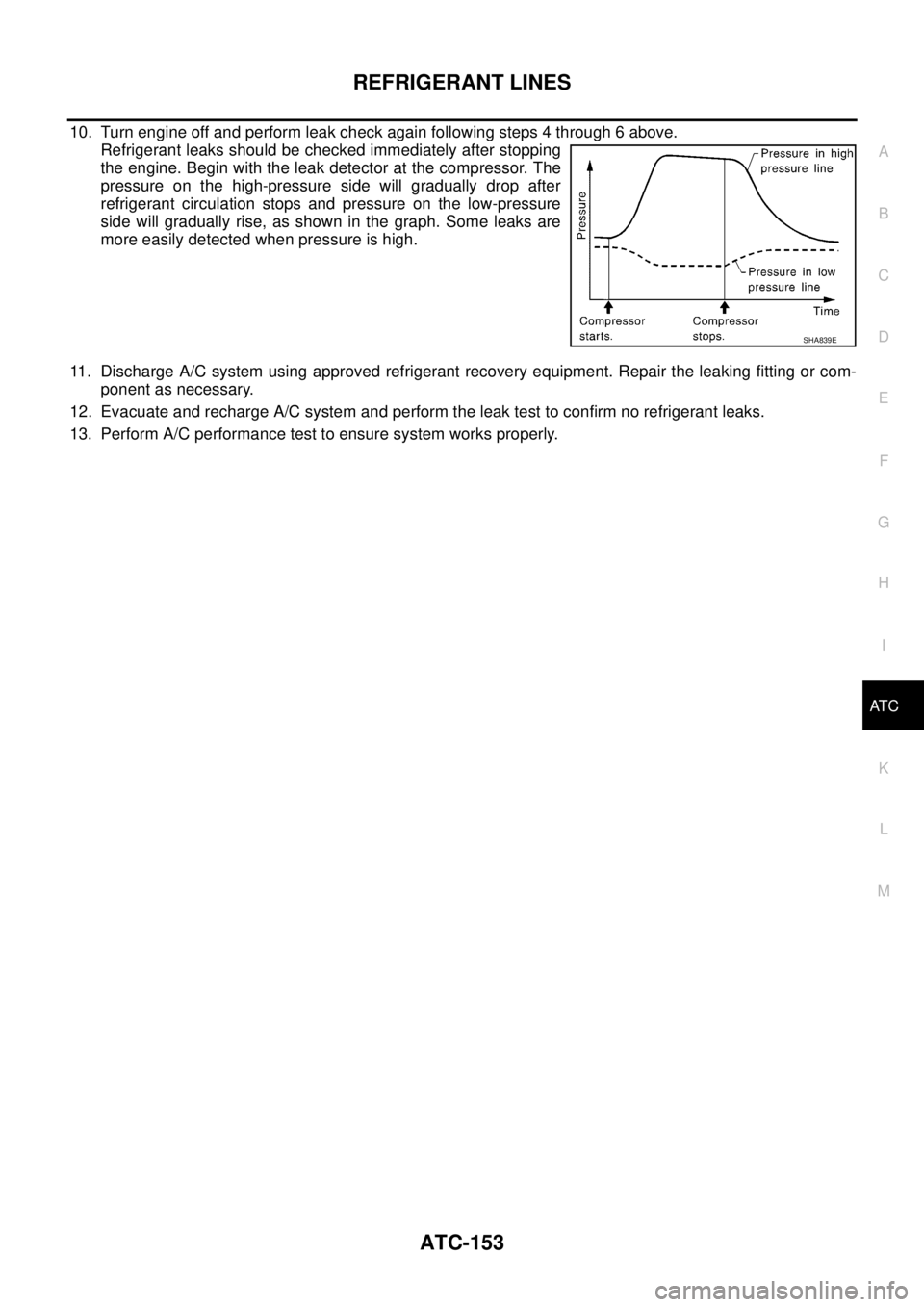
10. Turn engine off and perform leak check again following steps 4 through 6 above.
Refrigerant leaks should be checked immediately after stopping
the engine. Begin with the leak detector at the compressor. The
pressure on the high-pressure side will gradually drop after
refrigerant circulation stops and pressure on the low-pressure
side will gradually rise, as shown in the graph. Some leaks are
more easily detected when pressure is high.
11. Discharge A/C system using approved refrigerant recovery equipment. Repair the leaking fitting or com-
ponent as necessary.
12. Evacuate and recharge A/C system and perform the leak test to confirm no refrigerant leaks.
13. Perform A/C performance test to ensure system works properly.
SHA839E
Page 587 of 3171

BL-3
C
D
E
F
G
H
J
K
L
MA
B
BL INSTALLATION ................................................. 136
Removal and Installation of Fuel Lid Lock Striker. 137
REMOVAL ......................................................... 137
INSTALLATION ................................................. 137
THEFT WARNING SYSTEM .................................. 138
Component Parts and Harness Connector Location. 138
KING CAB ......................................................... 138
DOUBLE CAB ................................................... 139
System Description .............................................. 140
DESCRIPTION .................................................. 140
POWER SUPPLY AND GROUND CIRCUIT .... 141
INITIAL CONDITION TO ACTIVATE THE SYS-
TEM ................................................................... 141
THEFT WARNING SYSTEM ALARM OPERA-
TION .................................................................. 141
THEFT WARNING SYSTEM DEACTIVATION . 141
CAN Communication System Description ............ 141
Schematic ............................................................ 142
Wiring Diagram — VEHSEC — for LHD Models . 143
Wiring Diagram — VEHSEC — for RHD Models . 149
Terminals and Reference Value for BCM ............. 155
Terminals and Reference Value for IPDM E/R ..... 156
CONSULT-II Function (BCM) ............................... 156
CONSULT-II INSPECTION PROCEDURE ....... 156
CONSULT-II APPLICATION ITEM .................... 157
Trouble Diagnosis ................................................ 159
WORK FLOW .................................................... 159
Preliminary Check ................................................ 160
Symptom Chart .................................................... 161
Diagnostic Procedure 1 ........................................ 162
CHECK DOOR SWITCH (DOUBLE CAB) ........ 162
CHECK DOOR SWITCH (KING CAB) .............. 164
CHECK HOOD SWITCH ................................... 166
Diagnostic Procedure 2 ........................................ 168
Diagnostic Procedure 3 ........................................ 169
Diagnostic Procedure 4 ........................................ 169
NATS(NISSAN ANTI-THEFT SYSTEM) ................. 170Component Parts and Harness Connector Location.170
System Description ...............................................171
System Composition .............................................172
ECM Re-communicating Function ........................172
Wiring Diagram — NATS — .................................173
Terminals and Reference Value for BCM .............174
CONSULT-II Function ...........................................174
CONSULT-II INSPECTION PROCEDURE ........174
CONSULT-II DIAGNOSTIC TEST MODE FUNC-
TION ..................................................................175
HOW TO READ SELF-DIAGNOSTIC RESULTS.176
NATS SELF-DIAGNOSTIC RESULTS ITEM
CHART ..............................................................176
Trouble Diagnosis Procedure ...............................177
WORK FLOW ....................................................177
Trouble Diagnoses ...............................................178
SYMPTOM MATRIX CHART 1 ..........................178
SYMPTOM MATRIX CHART 2 ..........................178
Diagnostic Procedure 1 ........................................179
Diagnostic Procedure 2 ........................................181
Diagnostic Procedure 3 ........................................181
Diagnostic Procedure 4 ........................................184
Diagnostic Procedure 5 ........................................185
Diagnostic Procedure 6 ........................................187
Removal and Installation of NATS Antenna Amp . 188
REMOVAL .........................................................188
INSTALLATION .................................................188
CAB AND REAR BODY .........................................189
Body Mounting (King Cab) ...................................189
Body Mounting (Double Cab) ...............................190
BODY REPAIR ........................................................191
Body Alignment ....................................................191
DESCRIPTION ..................................................191
ENGINE COMPARTMENT ................................192
UNDERBODY ...................................................194
PASSENGER COMPARTMENT .......................196
REAR BODY .....................................................201
Page 591 of 3171

SQUEAK AND RATTLE TROUBLE DIAGNOSES
BL-7
C
D
E
F
G
H
J
K
L
MA
B
BL
DUPLICATE THE NOISE AND TEST DRIVE
If possible, drive the vehicle with the customer until the noise is duplicated. Note any additional information on
the Diagnostic Worksheet regarding the conditions or location of the noise. This information can be used to
duplicate the same conditions when you confirm the repair.
If the noise can be duplicated easily during the test drive, to help identify the source of the noise, try to dupli-
cate the noise with the vehicle stopped by doing one or all of the following:
1) Close a door.
2) Tap or push/pull around the area where the noise appears to be coming from.
3) Rev the engine.
4) Use a floor jack to recreate vehicle “twist”.
5) At idle, apply engine load (electrical load, half-clutch on M/T models, drive position on A/T models).
6) Raisethevehicleonahoistandhitatirewitharubberhammer.
lDrive the vehicle and attempt to duplicate the conditions the customer states exist when the noise occurs.
lIf it is difficult to duplicate the noise, drive the vehicle slowly on an undulating or rough road to stress the
vehicle body.
CHECK RELATED SERVICE BULLETINS
After verifying the customer concern or symptom, check ASIST for Technical Service Bulletins (TSBs) related
to that concern or symptom.
If a TSB relates to the symptom, follow the procedure to repair the noise.
LOCATE THE NOISE AND IDENTIFY THE ROOT CAUSE
1. Narrow down the noise to a general area. To help pinpoint the source of the noise, use a listening tool
(Engine Ear or mechanics stethoscope).
2. Narrow down the noise to a more specific area and identify the cause of the noise by:
lremoving the components in the area that you suspect the noise is coming from.
Do not use too much force when removing clips and fasteners, otherwise clips and fastener can be broken
or lost during the repair, resulting in the creation of new noise.
ltapping or pushing/pulling the component that you suspect is causing the noise.
Do not tap or push/pull the component with excessive force, otherwise the noise will be eliminated only
temporarily.
lfeeling for a vibration with your hand by touching the component(s) that you suspect is (are) causing the
noise.
lplacing a piece of paper between components that you suspect are causing the noise.
llooking for loose components and contact marks.
Refer toBL-8, "
Generic Squeak and Rattle Troubleshooting".
REPAIR THE CAUSE
lIf the cause is a loose component, tighten the component securely.
lIf the cause is insufficient clearance between components:
–separate components by repositioning or loosening and retightening the component, if possible.
–insulate components with a suitable insulator such as urethane pads, foam blocks, felt cloth tape or ure-
thane tape are available through your authorized Nissan Parts Department.
CAUTION:
Do not use excessive force as many components are constructed of plastic and may be damaged.
NOTE:
Always check with the Parts Department for the latest parts information.
Each item can be ordered separately as needed.
URETHANE PADS [1.5 mm (0.059 in) thick]
Insulates connectors, harness, etc.
76268-9E005: 100´135 mm (3.94´5.31 in)/76884-71L01: 60´85 mm (2.36´3.35 in)/76884-71L02: 15´
25 mm (0.59´0.98 in)
INSULATOR (Foam blocks)
Insulates components from contact. Can be used to fill space behind a panel.
73982-9E000: 45 mm (1.77 in) thick, 50´50 mm (1.97´1.97 in)/73982-50Y00: 10 mm (0.39 in) thick, 50
´50 mm (1.97´1.97 in)
INSULATOR (Light foam block)
80845-71L00: 30 mm (1.18 in) thick, 30´50 mm (1.18´1.97 in)