2005 NISSAN NAVARA check engine
[x] Cancel search: check enginePage 337 of 3171

ATC-3
C
D
E
F
G
H
I
K
L
MA
B
AT C BLOWER MOTOR .................................................. 121
Components ......................................................... 121
Removal and Installation ...................................... 121
REMOVAL ......................................................... 121
INSTALLATION ................................................. 121
AIR CONDITIONER FILTER ................................... 122
Removal and Installation ...................................... 122
FUNCTION ........................................................ 122
REPLACEMENT TIMING .................................. 122
REPLACEMENT PROCEDURE ....................... 122
HEATER & COOLING UNIT ASSEMBLY .............. 124
Components ......................................................... 124
Removal and Installation ...................................... 126
REMOVAL ......................................................... 126
INSTALLATION ................................................. 126
HEATER CORE ...................................................... 127
Components ......................................................... 127
Removal and Installation ...................................... 127
REMOVAL ......................................................... 127
INSTALLATION ................................................. 127
HEATER PUMP ...................................................... 128
Components ......................................................... 128
Removal and Installation ...................................... 128
REMOVAL ......................................................... 128
INSTALLATION ................................................. 128
INTAKE DOOR MOTOR ......................................... 129
Components ......................................................... 129
Removal and Installation ...................................... 129
REMOVAL ......................................................... 129
INSTALLATION ................................................. 129
MODE DOOR MOTOR ........................................... 130
Components ......................................................... 130
Removal and Installation ...................................... 130
REMOVAL ......................................................... 130
INSTALLATION ................................................. 130
AIR MIX DOOR MOTOR ......................................... 131
Components ......................................................... 131
Removal and Installation ...................................... 131
AIR MIX DOOR MOTOR (DRIVER) .................. 131
AIR MIX DOOR MOTOR (PASSENGER) ......... 131
VARIABLE BLOWER CONTROL .......................... 133
Components ......................................................... 133
Removal and Installation ...................................... 133
REMOVAL ......................................................... 133
INSTALLATION ................................................. 133
DUCTS AND GRILLES .......................................... 134
Components ......................................................... 134
Removal and Installation ...................................... 136
CONSOLE DUCTS AND CONSOLE GRILLE .. 136
DEFROSTER NOZZLE ..................................... 136
RH AND LH SIDE DEMISTER DUCT ............... 136
RH AND LH VENTILATOR DUCT ..................... 136
CENTER VENTILATOR DUCT ......................... 136
FLOOR CONNECTOR DUCT ........................... 136
FRONT AND REAR FLOOR DUCTS ............... 137
REAR OVERHEAD DUCTS .............................. 137
SIDE REAR FLOOR DUCT .............................. 137
GRILLES ........................................................... 137REFRIGERANT LINES ...........................................138
HFC-134a (R-134a) Service Procedure ...............138
SETTING OF SERVICE TOOLS AND EQUIP-
MENT ................................................................138
Components .........................................................140
Removal and Installation for Compressor ............142
REMOVAL .........................................................142
INSTALLATION .................................................142
Removal and Installation for Compressor Clutch . 143
REMOVAL .........................................................143
INSPECTION ....................................................144
INSTALLATION .................................................144
BREAK-IN OPERATION ....................................146
Removal and Installation for High-pressure Flexible
A/C Hose ..............................................................146
REMOVAL .........................................................146
INSTALLATION .................................................146
Removal and Installation for High-pressure A/C
Pipe ......................................................................146
REMOVAL .........................................................146
INSTALLATION .................................................146
Removal and Installation for Low-pressure Flexible
A/C Hose ..............................................................146
REMOVAL .........................................................146
INSTALLATION .................................................146
Removal and Installation for Low-pressure A/C Pipe.147
REMOVAL .........................................................147
INSTALLATION .................................................147
Removal and Installation for Refrigerant Pressure
Sensor ..................................................................147
REMOVAL .........................................................147
INSTALLATION .................................................147
Removal and Installation for Condenser ..............147
REMOVAL .........................................................147
INSTALLATION .................................................148
Removal and Installation for Evaporator ..............149
REMOVAL .........................................................149
INSTALLATION .................................................149
Removal and Installation for Expansion Valve ......150
REMOVAL .........................................................150
INSTALLATION .................................................150
Checking for Refrigerant Leaks ............................150
Checking System for Leaks Using the Fluorescent
Leak Detector .......................................................150
Dye Injection .........................................................151
Electronic Refrigerant Leak Detector ....................151
PRECAUTIONS FOR HANDLING LEAK
DETECTOR .......................................................151
CHECKING PROCEDURE ...............................152
SERVICE DATA AND SPECIFICATIONS (SDS) ....154
Service Data and Specifications (SDS) ................154
COMPRESSOR ................................................154
LUBRICANT ......................................................154
REFRIGERANT .................................................154
ENGINE IDLING SPEED ..................................154
BELT TENSION .................................................154
Page 346 of 3171
ATC-12
PRECAUTIONS
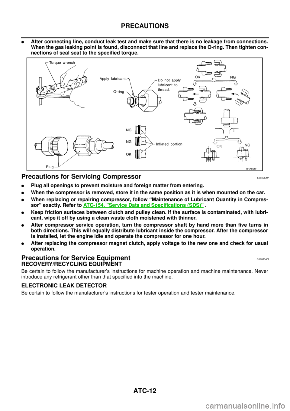
lAfter connecting line, conduct leak test and make sure that there is no leakage from connections.
When the gas leaking point is found, disconnect that line and replace the O-ring. Then tighten con-
nections of seal seat to the specified torque.
Precautions for Servicing CompressorEJS006AP
lPlug all openings to prevent moisture and foreign matter from entering.
lWhen the compressor is removed, store it in the same position as it is when mounted on the car.
lWhen replacing or repairing compressor, follow “Maintenance of Lubricant Quantity in Compres-
sor” exactly. Refer toATC-154, "
Service Data and Specifications (SDS)".
lKeep friction surfaces between clutch and pulley clean. If the surface is contaminated, with lubri-
cant, wipe it off by using a clean waste cloth moistened with thinner.
lAfter compressor service operation, turn the compressor shaft by hand more than five turns in
both directions. This will equally distribute lubricant inside the compressor. After the compressor
is installed, let the engine idle and operate the compressor for one hour.
lAfter replacing the compressor magnet clutch, apply voltage to the new one and check for usual
operation.
Precautions for Service EquipmentEJS006AQ
RECOVERY/RECYCLING EQUIPMENT
Be certain to follow the manufacturer’s instructions for machine operation and machine maintenance. Never
introduce any refrigerant other than that specified into the machine.
ELECTRONIC LEAK DETECTOR
Be certain to follow the manufacturer’s instructions for tester operation and tester maintenance.
RHA861F
Page 358 of 3171
ATC-24
LUBRICANT
LUBRICANT
PFP:KLG00
Maintenance of Lubricant Quantity in CompressorEJS006AZ
The lubricant in the compressor circulates through the system with the refrigerant. Add lubricant to compres-
sor when replacing any component or after a large refrigerant leakage has occurred. It is important to maintain
the specified amount.
If lubricant quantity is not maintained properly, the following malfunctions may result:
lLack of lubricant: May lead to a seized compressor
lExcessive lubricant: Inadequate cooling (thermal exchange interference)
LUBRICANT
Name: NISSAN A/C System Lubricant Type S (DH-PS) or equivalent
Part number: KLH00-PAGS0
CHECKING AND ADJUSTING
CAUTION:
If excessive lubricant leakage is noted, do not perform the lubricant return operation.
Start the engine and set the following conditions:
Test Condition
lEngine speed: Idling to 1,200 rpm
lA/C switch: On
lBlower speed: Max. position
lTemp. control: Optional [Set so that intake air temperature is 25°to 30°C(77°to 86°F)]
lIntake position: Recirculation ( )
lPerform lubricant return operation for about ten minutes
Adjust the lubricant quantity according to the following table.
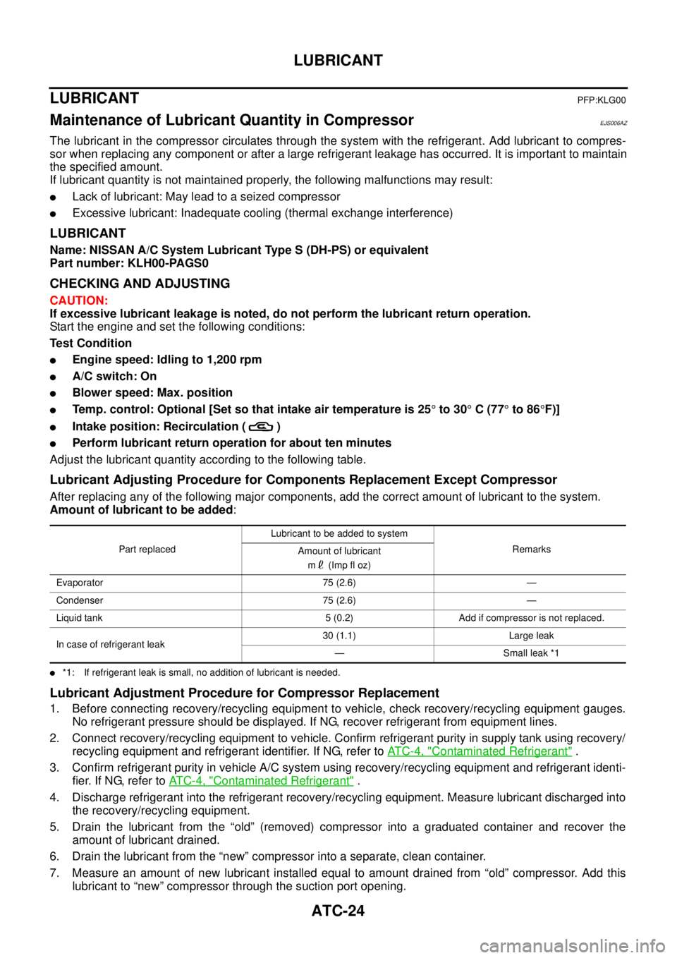
Lubricant Adjusting Procedure for Components Replacement Except Compressor
After replacing any of the following major components, add the correct amount of lubricant to the system.
Amount of lubricant to be added:
l*1: If refrigerant leak is small, no addition of lubricant is needed.
Lubricant Adjustment Procedure for Compressor Replacement
1. Before connecting recovery/recycling equipment to vehicle, check recovery/recycling equipment gauges.
No refrigerant pressure should be displayed. If NG, recover refrigerant from equipment lines.
2. Connect recovery/recycling equipment to vehicle. Confirm refrigerant purity in supply tank using recovery/
recycling equipment and refrigerant identifier. If NG, refer toAT C - 4 , "
Contaminated Refrigerant".
3. Confirm refrigerant purity in vehicle A/C system using recovery/recycling equipment and refrigerant identi-
fier. If NG, refer toAT C - 4 , "
Contaminated Refrigerant".
4. Discharge refrigerant into the refrigerant recovery/recycling equipment. Measure lubricant discharged into
the recovery/recycling equipment.
5. Drain the lubricant from the “old” (removed) compressor into a graduated container and recover the
amount of lubricant drained.
6. Drain the lubricant from the “new” compressor into a separate, clean container.
7. Measure an amount of new lubricant installed equal to amount drained from “old” compressor. Add this
lubricant to “new” compressor through the suction port opening.
Part replacedLubricant to be added to system
Remarks
Amount of lubricant
m(Impfloz)
Evaporator 75 (2.6) —
Condenser 75 (2.6) —
Liquid tank 5 (0.2) Add if compressor is not replaced.
In case of refrigerant leak30 (1.1) Large leak
— Small leak *1
Page 391 of 3171

TROUBLE DIAGNOSIS
ATC-57
C
D
E
F
G
H
I
K
L
MA
B
AT C
Operational CheckEJS006BH
The purpose of the operational check is to confirm that the system operates properly.
CHECKING MEMORY FUNCTION
1. Set the temperature to 32°C(90°F).
2. Turn blower control dial counterclockwise until system shuts
OFF.
3. Turn ignition switch OFF.
4. Turn ignition switch ON.
5. Press the AUTO switch.
6. Confirm that the set temperature remains at previous tempera-
ture.
7. Turn blower control dial counterclockwise until system shuts
OFF.
If NG, go to trouble diagnosis procedure forATC-104, "
Memory
Function".
If OK, continue with next check.
CHECKING BLOWER
1. Press the AUTO switch. Blower should operate on low speed.
The blower symbol should have one blade lit (on display).
2. Turn the blower control dial again, and continue checking blower
speed and blower symbol until all speeds are checked.
3. Leave blower on MAX speed.
If NG, go to trouble diagnosis procedure forAT C - 8 2 , "
DIAGNOSTIC
PROCEDURE FOR BLOWER MOTOR".
If OK, continue with next check.Conditions : Engine running and at normal operating temperature
MJIB0335E
MJIB0336E
MJIB0335E
MJIB0337E
Page 425 of 3171
TROUBLE DIAGNOSIS
ATC-91
C
D
E
F
G
H
I
K
L
MA
B
AT C
8.CHECK REFRIGERANT PRESSURE SENSOR
WITH CONSULT-II
1. Start engine.
2. Check voltage of refrigerant pressure sensor. Refer toAT C - 3 3 , "
CONSULT-II Function (BCM)".
WITHOUT CONSULT-II
1. Start engine.
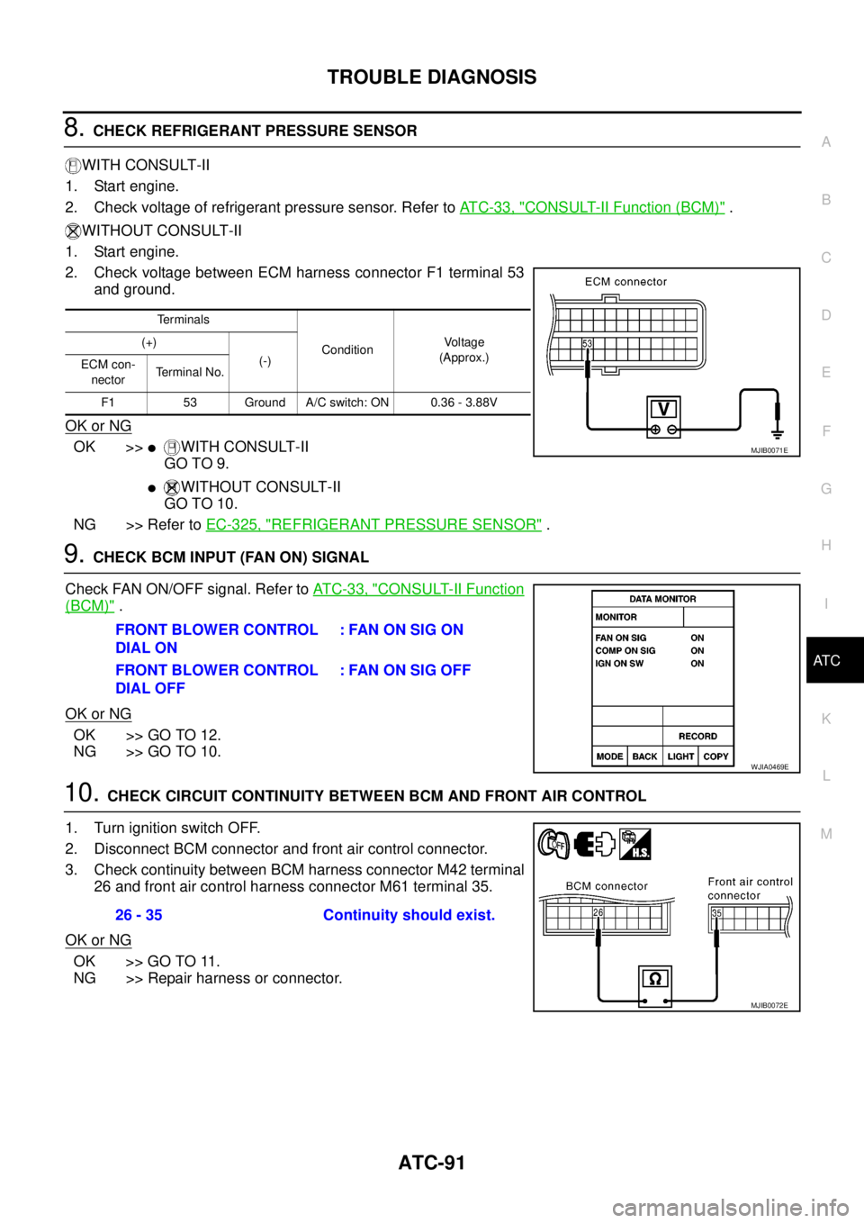
2. Check voltage between ECM harness connector F1 terminal 53
and ground.
OK or NG
OK >>lWITH CONSULT-II
GO TO 9.
lWITHOUT CONSULT-II
GO TO 10.
NG >> Refer toEC-325, "
REFRIGERANT PRESSURE SENSOR".
9.CHECK BCM INPUT (FAN ON) SIGNAL
Check FAN ON/OFF signal. Refer toAT C - 3 3 , "
CONSULT-II Function
(BCM)".
OK or NG
OK >> GO TO 12.
NG >> GO TO 10.
10.CHECK CIRCUIT CONTINUITY BETWEEN BCM AND FRONT AIR CONTROL
1. Turn ignition switch OFF.
2. Disconnect BCM connector and front air control connector.
3. Check continuity between BCM harness connector M42 terminal
26 and front air control harness connector M61 terminal 35.
OK or NG
OK >> GO TO 11.
NG >> Repair harness or connector.
Te r m i n a l s
ConditionVo l ta g e
(Approx.) (+)
(-)
ECM con-
nectorTerminal No.
F1 53 Ground A/C switch: ON 0.36 - 3.88V
MJIB0071E
FRONT BLOWER CONTROL
DIAL ON: FAN ON SIG ON
FRONT BLOWER CONTROL
DIAL OFF:FANONSIGOFF
WJIA0469E
26 - 35 Continuity should exist.
MJIB0072E
Page 431 of 3171
TROUBLE DIAGNOSIS
ATC-97
C
D
E
F
G
H
I
K
L
MA
B
AT C
TROUBLE DIAGNOSES FOR UNUSUAL PRESSURE
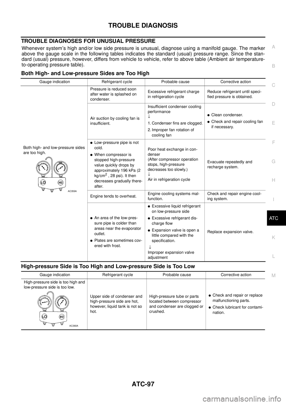
Whenever system¢s high and/or low side pressure is unusual, diagnose using a manifold gauge. The marker
above the gauge scale in the following tables indicates the standard (usual) pressure range. Since the stan-
dard (usual) pressure, however, differs from vehicle to vehicle, refer to above table (Ambient air temperature-
to-operating pressure table).
Both High- and Low-pressure Sides are Too High
High-pressure Side is Too High and Low-pressure Side is Too Low
Gauge indication Refrigerant cycle Probable cause Corrective action
Both high- and low-pressure sides
are too high.Pressure is reduced soon
after water is splashed on
condenser.Excessive refrigerant charge
in refrigeration cycleReduce refrigerant until speci-
fied pressure is obtained.
Air suction by cooling fan is
insufficient.Insufficient condenser cooling
performance
¯
1. Condenser fins are clogged.
2. Improper fan rotation of
cooling fan
lClean condenser.
lCheck and repair cooling fan
if necessary.
lLow-pressure pipe is not
cold.
lWhen compressor is
stopped high-pressure
value quickly drops by
approximately 196 kPa (2
kg/cm
2, 28 psi). It then
decreases gradually there-
after.Poor heat exchange in con-
denser
(After compressor operation
stops, high-pressure
decreases too slowly.)
¯
Air in refrigeration cycleEvacuate repeatedly and
recharge system.
Engine tends to overheat.Engine cooling systems mal-
function.Check and repair engine cool-
ing system.
lAn area of the low-pres-
sure pipe is colder than
areas near the evaporator
outlet.
lPlates are sometimes cov-
ered with frost.
lExcessive liquid refrigerant
on low-pressure side
lExcessive refrigerant dis-
charge flow
lExpansion valve is open a
little compared with the
specification.
¯
Improper expansion valve
adjustmentReplace expansion valve.
AC359A
Gauge indication Refrigerant cycle Probable cause Corrective action
High-pressure side is too high and
low-pressure side is too low.
Upper side of condenser and
high-pressure side are hot,
however, liquid tank is not so
hot.High-pressure tube or parts
located between compressor
and condenser are clogged or
crushed.
lCheck and repair or replace
malfunctioning parts.
lCheck lubricant for contami-
nation.
AC360A
Page 434 of 3171
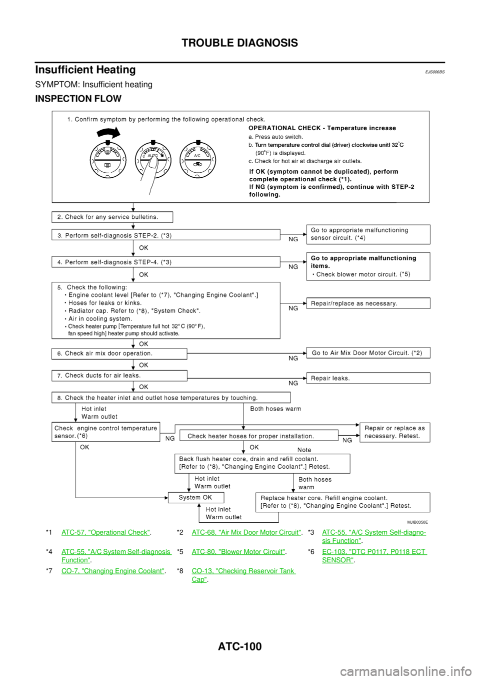
ATC-100
TROUBLE DIAGNOSIS
Insufficient Heating
EJS006BS
SYMPTOM: Insufficient heating
INSPECTION FLOW
*1ATC-57, "Operational Check".*2AT C - 6 8 , "Air Mix Door Motor Circuit".*3ATC-55, "A/C System Self-diagno-
sis Function".
*4ATC-55, "
A/C System Self-diagnosis
Function".*5AT C - 8 0 , "
Blower Motor Circuit".*6EC-103, "DTC P0117, P0118 ECT
SENSOR".
*7CO-7, "
Changing Engine Coolant".*8CO-13, "Checking Reservoir Tank
Cap".
MJIB0350E
Page 439 of 3171
TROUBLE DIAGNOSIS
ATC-105
C
D
E
F
G
H
I
K
L
MA
B
AT C
Ambient Sensor CircuitEJS006BW
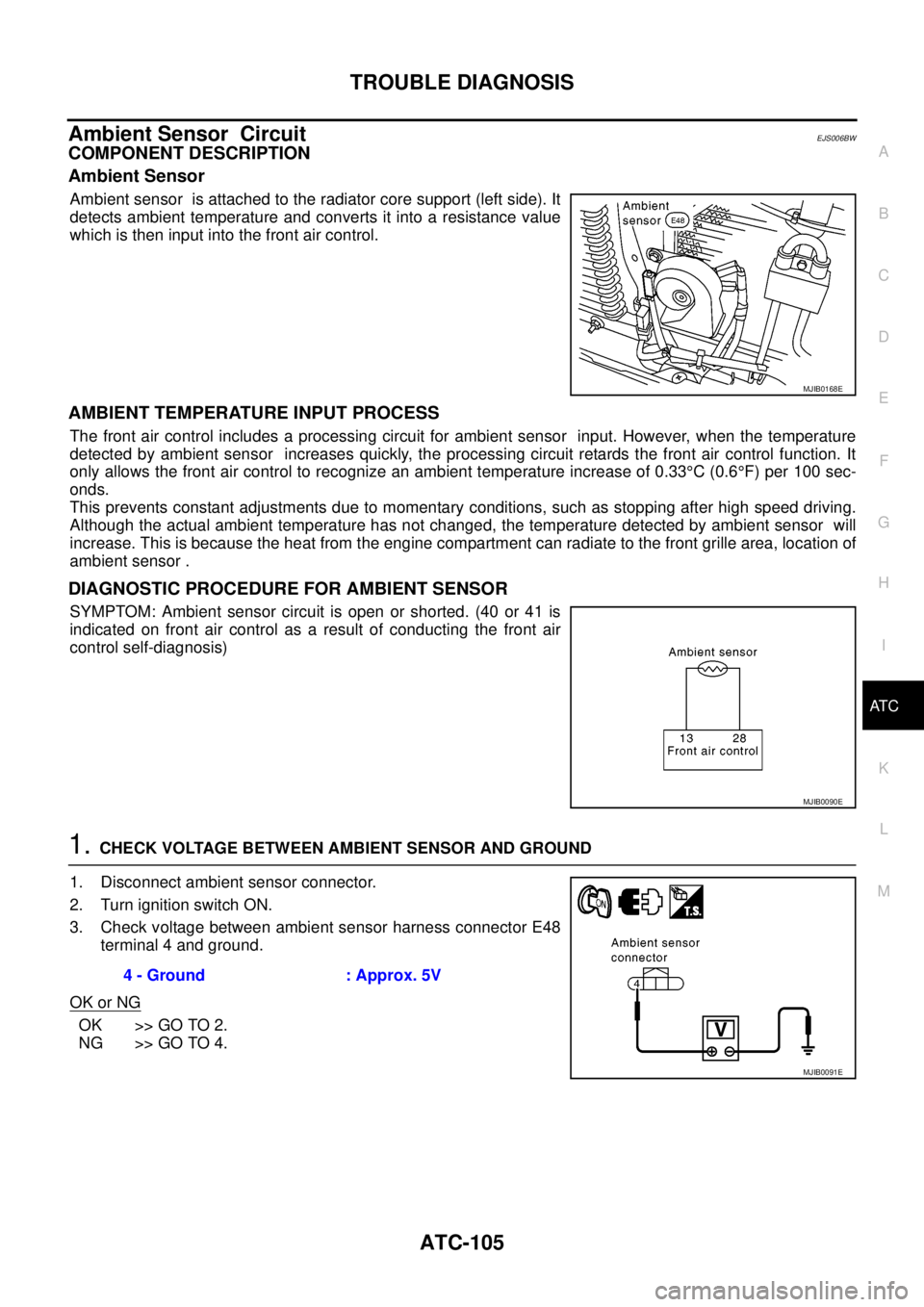
COMPONENT DESCRIPTION
Ambient Sensor
Ambient sensor is attached to the radiator core support (left side). It
detects ambient temperature and converts it into a resistance value
which is then input into the front air control.
AMBIENT TEMPERATURE INPUT PROCESS
The front air control includes a processing circuit for ambient sensor input. However, when the temperature
detected by ambient sensor increases quickly, the processing circuit retards the front air control function. It
only allows the front air control to recognize an ambient temperature increase of 0.33°C(0.6°F) per 100 sec-
onds.
This prevents constant adjustments due to momentary conditions, such as stopping after high speed driving.
Although the actual ambient temperature has not changed, the temperature detected by ambient sensor will
increase. This is because the heat from the engine compartment can radiate to the front grille area, location of
ambient sensor .
DIAGNOSTIC PROCEDURE FOR AMBIENT SENSOR
SYMPTOM: Ambient sensor circuit is open or shorted. (40 or 41 is
indicated on front air control as a result of conducting the front air
control self-diagnosis)
1.CHECK VOLTAGE BETWEEN AMBIENT SENSOR AND GROUND
1. Disconnect ambient sensor connector.
2. Turn ignition switch ON.
3. Check voltage between ambient sensor harness connector E48
terminal 4 and ground.
OK or NG
OK >> GO TO 2.
NG >> GO TO 4.
MJIB0168E
MJIB0090E
4 - Ground : Approx. 5V
MJIB0091E