Page 828 of 1500

AUTO A/C DIAGNOSIS
HEATER, AIR CONDITIONING AND VENTILATION55-127
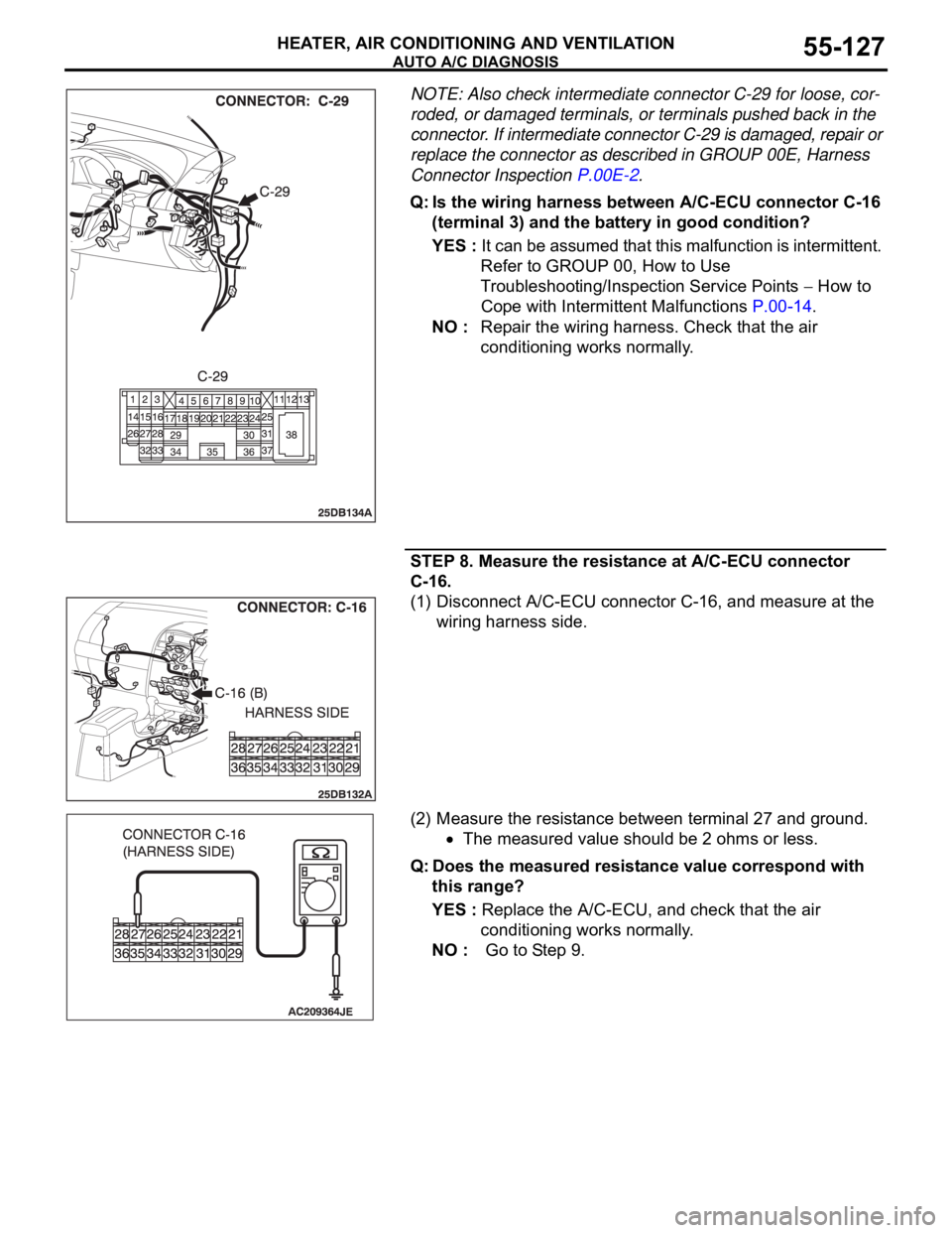
NOTE: Also check intermediate connector C-29 for loose, cor-
roded, or damaged terminals, or terminals pushed back in the
connector. If intermediate connector C-29 is damaged, repair or
replace the connector as described in GROUP 00E, Harness
Connector Inspection P.00E-2.
Q: Is the wiring harness between A/C-ECU connector C-16
(terminal 3) and the battery in good condition?
YES : It can be assumed that this malfunction is intermittent.
Refer to GROUP 00, How to Use
Troubleshooting/Inspection Service Points
How to
Cope with Intermittent Malfunctions P.00-14.
NO : Repair the wiring harness. Check that the air
conditioning works normally.
STEP 8. Measure the resistance at A/C-ECU connector
C-16.
(1) Disconnect A/C-ECU connector C-16, and measure at the
wiring harness side.
(2) Measure the resistance between terminal 27 and ground.
The measured value should be 2 ohms or less.
Q: Does the measured resistance value correspond with
this range?
YES : Replace the A/C-ECU, and check that the air
conditioning works normally.
NO : Go to Step 9.
Page 835 of 1500

AUTO A/C DIAGNOSIS
HEATER, AIR CONDITIONING AND VENTILATION55-134
Air outlet c/o
potentiometer55 Mode selection
damper control
motor potentiometerIgnition switch: ON Damper
positionOpening degree (V)
FA C E A p pr o x . 5
FOOT Approx. 3.75
FOOT/DEF. Approx. 2.5
DEF. Approx. 1.75
Air outlet c/o
potentiometer
(target)56 Target value for
mode selection
damper control
motor potentiometerIgnition switch: ON Damper
positionOpening degree (V)
FA C E A p pr o x . 5
FOOT Approx. 3.75
FOOT/DEF. Approx. 2.5
DEF. Approx. 1.75
In/out air
changeover
damper motor65 Outside/inside air
selection damper
control motorIgnition switch: ON Damper set
positionDamper position
Fresh air
positionFRESH
Air recirculation
positionRECIRC
Front blower fan 68 Blower motor Ignition switch: ON The actual air
volume (blower
motor speed)
corresponds to the
air volume shown on
the diagnostic tool.
Front blower
motor voltage 71 Blower motor Ignition switch: ON The air volume set
by the heater control
corresponds to the
value shown on the
diagnostic tool. (V)
Air conditioning
switch state1 Air conditioning
switchIgnition switch: ON Air conditioning
switch: ONDiagnostic tool
indication: "pressed"
Air conditioning
switch: OFFDiagnostic tool
indication: "release"
Rear defogger
switch state7 Rear window
defogger switchIgnition switch: ON Rear window
defogger
switch: ONDiagnostic tool
indication: "pressed"
Rear window
defogger
switch: OFFDiagnostic tool
indication: "release"
Refrigerant
pressure73 Refrigerant pressure Ignition switch: ON The diagnostic tool
indication is normal MUT-III
DIAGNOSTIC
TOOL DISPLAYITEM
NO.INSPECTION ITEM INSPECTION REQUIREMENT NORMAL VALUE
Page 836 of 1500

AUTO A/C DIAGNOSIS
HEATER, AIR CONDITIONING AND VENTILATION55-135
Temperature
setting23 Temperature setting
actualIgnition switch: ON The actual setting
corresponds with
diagnostic tool
display.
Vehicle speed 26 Actual vehicle speed Ignition switch: ON The vehicle speed
corresponds with
diagnostic tool
display.
A/C compressor
drive request27 Compressor clutch Engine: ON
Compressor:
ONDiagnostic tool
indication: "ON"
Compressor:
OFFDiagnostic tool
indication: "OFF"
Illumination 15 Display lighting Ignition switch: ON
Lights: ON
Diagnostic tool
indication: "ON"
Lights: OFF
Diagnostic tool
indication: "OFF"
Engine speed 23 Actual engine speed Engine: ON The engine speed
corresponds with
diagnostic tool
display.
In/out air select
switch state3 In/out air select
switch Ignition switch: ON In/out air
switch: ONDiagnostic tool
indication: "pressed"
In/out air
switch: OFFDiagnostic tool
indication: "release"
Rear defogger
relay72 Rear defogger relay Ignition switch: ON
Rear defogger:
ONDiagnostic tool
indication: "ON"
Rear defogger:
OFFDiagnostic tool
indication: "OFF" MUT-III
DIAGNOSTIC
TOOL DISPLAYITEM
NO.INSPECTION ITEM INSPECTION REQUIREMENT NORMAL VALUE
Page 846 of 1500

ON-VEHICLE SERVICE
HEATER, AIR CONDITIONING AND VENTILATION55-145
LOST CHARGE
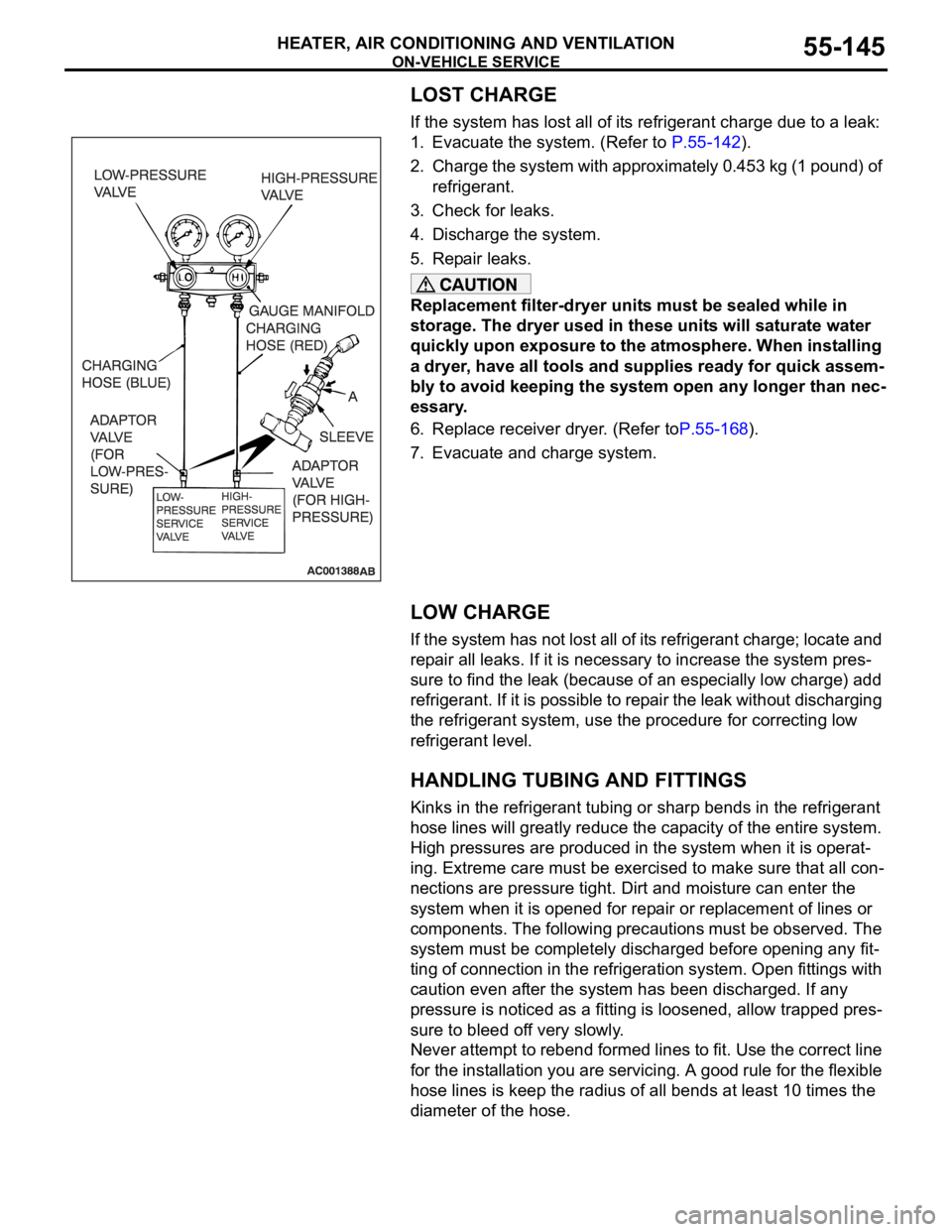
If the system has lost all of its refrigerant charge due to a leak:
1. Evacuate the system. (Refer to P.55-142).
2. Charge the system with approximately 0.453 kg (1 pound) of
refrigerant.
3. Check for leaks.
4. Discharge the system.
5. Repair leaks.
Replacement filter-dryer units must be sealed while in
storage. The dryer used in these units will saturate water
quickly upon exposure to the atmosphere. When installing
a dryer, have all tools and supplies ready for quick assem-
bly to avoid keeping the system open any longer than nec-
essary.
6. Replace receiver dryer. (Refer toP.55-168).
7. Evacuate and charge system.
LOW CHARGE
If the system has not lost all of its refrigerant charge; locate and
repair all leaks. If it is necessary to increase the system pres-
sure to find the leak (because of an especially low charge) add
refrigerant. If it is possible to repair the leak without discharging
the refrigerant system, use the procedure for correcting low
refrigerant level.
HANDLING TUBING AND FITTINGS
Kinks in the refrigerant tubing or sharp bends in the refrigerant
hose lines will greatly reduce the capacity of the entire system.
High pressures are produced in the system when it is operat-
ing. Extreme care must be exercised to make sure that all con-
nections are pressure tight. Dirt and moisture can enter the
system when it is opened for repair or replacement of lines or
components. The following precautions must be observed. The
system must be completely discharged before opening any fit-
ting of connection in the refrigeration system. Open fittings with
caution even after the system has been discharged. If any
pressure is noticed as a fitting is loosened, allow trapped pres-
sure to bleed off very slowly.
Never attempt to rebend formed lines to fit. Use the correct line
for the installation you are servicing. A good rule for the flexible
hose lines is keep the radius of all bends at least 10 times the
diameter of the hose.
Page 883 of 1500
GROUNDING
COMPONENT LOCATIONS70-4
GROUNDINGM1701000300522
NOTE: 1 to 15 numbers correspond to the body ground point numbers in CIRCUIT DIAGRAMS.
Page 905 of 1500
HOW TO DIAGNOSE
GENERAL 00E-4
INSPECTIONM1001004600139
1. Sight and sound checks
Check relay operation, blower motor rotation, light
illumination, etc. Listen for a "click" when some relay covers
are pushed down.
2. Simple checks
For example, if a headlight does not come on and a faulty
fuse or poor grounding is suspected, replace the fuse with a
new one. Or use a jumper wire to ground the light to the
body. Determine which part(s) is/are responsible for the
problem.
3. Checking with instruments
Use an appropriate instrument in an adequate range and
read the indication correctly.
Page 907 of 1500

HOW TO DIAGNOSE
GENERAL 00E-6
5. Ohmmeter
An ohmmeter is used to check continuity or measure
resistance of a switch or coil. If the measuring range has
been changed, the zero point must be adjusted before
measurement.
CHECKING FUSESM1001005000044
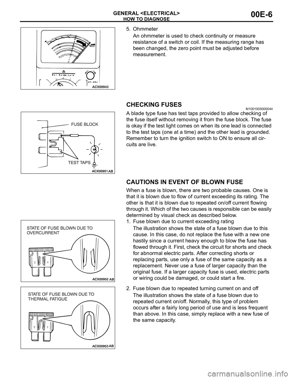
A blade type fuse has test taps provided to allow checking of
the fuse itself without removing it from the fuse block. The fuse
is okay if the test light comes on when its one lead is connected
to the test taps (one at a time) and the other lead is grounded.
Remember to turn the ignition switch to ON to ensure all cir-
cuits are live.
CAUTIONS IN EVENT OF BLOWN FUSE
When a fuse is blown, there are two probable causes. One is
that it is blown due to flow of current exceeding its rating. The
other is that it is blown due to repeated on/off current flowing
through it. Which of the two causes is responsible can be easily
determined by visual check as described below.
1. Fuse blown due to current exceeding rating
The illustration shows the state of a fuse blown due to this
cause. In this case, do not replace the fuse with a new one
hastily since a current heavy enough to blow the fuse has
flowed through it. First, check the circuit for shorts and check
for abnormal electric parts. After correcting shorts or
replacing parts, use only a fuse of the same capacity as a
replacement. Never use a fuse of larger capacity than the
original fuse. If a larger capacity fuse is used, electric parts
or wiring could be damaged, or could start a fire.
2. Fuse blown due to repeated turning current on and off
The illustration shows the state of a fuse blown due to
repeated current on/off. Normally, this type of problem
occurs after a fairly long period of use and is less frequent
than above. In this case, simply replace with a new fuse of
the same capacity.
Page 1007 of 1500

IGNITION SYSTEM
ENGINE ELECTRICAL16-30
IGNITION SYSTEM
GENERAL DESCRIPTIONM1163000100528
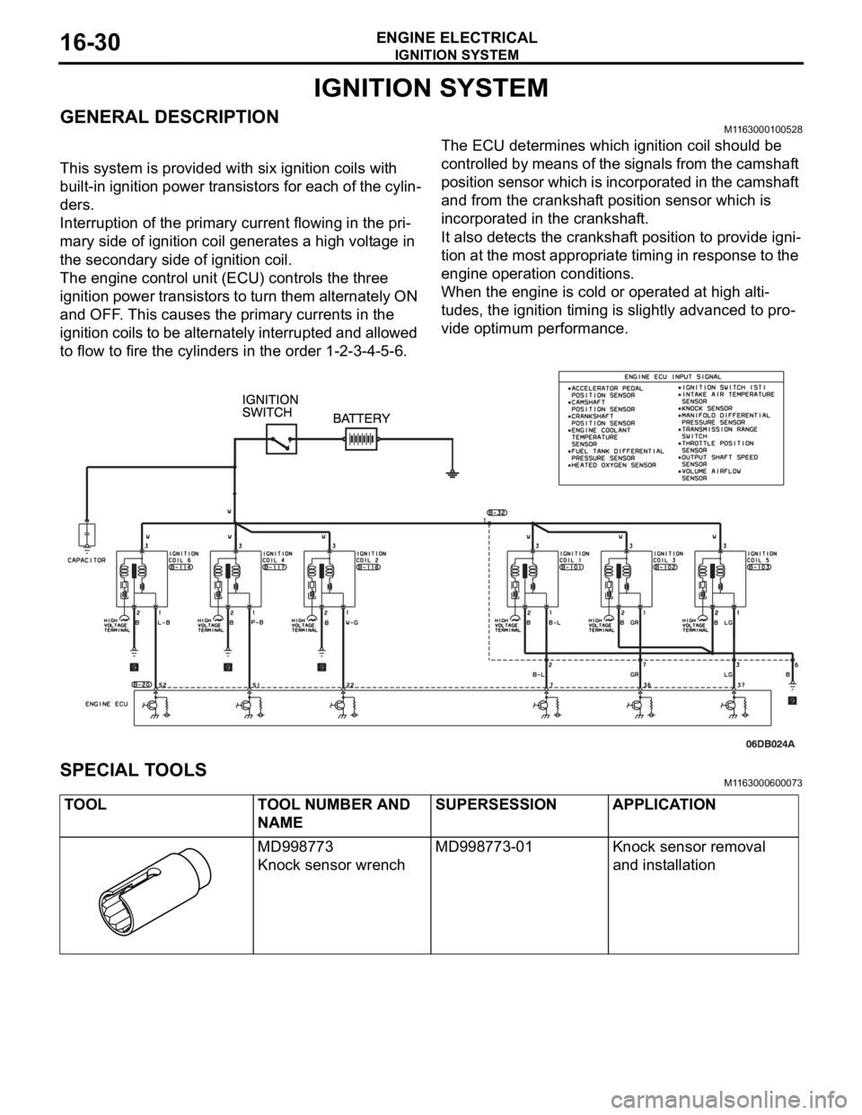
This system is provided with six ignition coils with
built-in ignition power transistors for each of the cylin-
ders.
Interruption of the primary current flowing in the pri-
mary side of ignition coil generates a high voltage in
the secondary side of ignition coil.
The engine control unit (ECU) controls the three
ignition power transistors to turn them alternately ON
and OFF. This causes the primary currents in the
ignition coils to be alternately interrupted and allowed
to flow to fire the cylinders in the order 1-2-3-4-5-6.The ECU determines which ignition coil should be
controlled by means of the signals from the camshaft
position sensor which is incorporated in the camshaft
and from the crankshaft position sensor which is
incorporated in the crankshaft.
It also detects the crankshaft position to provide igni-
tion at the most appropriate timing in response to the
engine operation conditions.
When the engine is cold or operated at high alti-
tudes, the ignition timing is slightly advanced to pro-
vide optimum performance.
SPECIAL TOOLSM1163000600073
TOOL TOOL NUMBER AND
NAMESUPERSESSION APPLICATION
MD998773
Knock sensor wrenchMD998773-01 Knock sensor removal
and installation