Page 1442 of 1500

DRIVE SHAFT ASSEMBLY
FRONT AXLE26-25
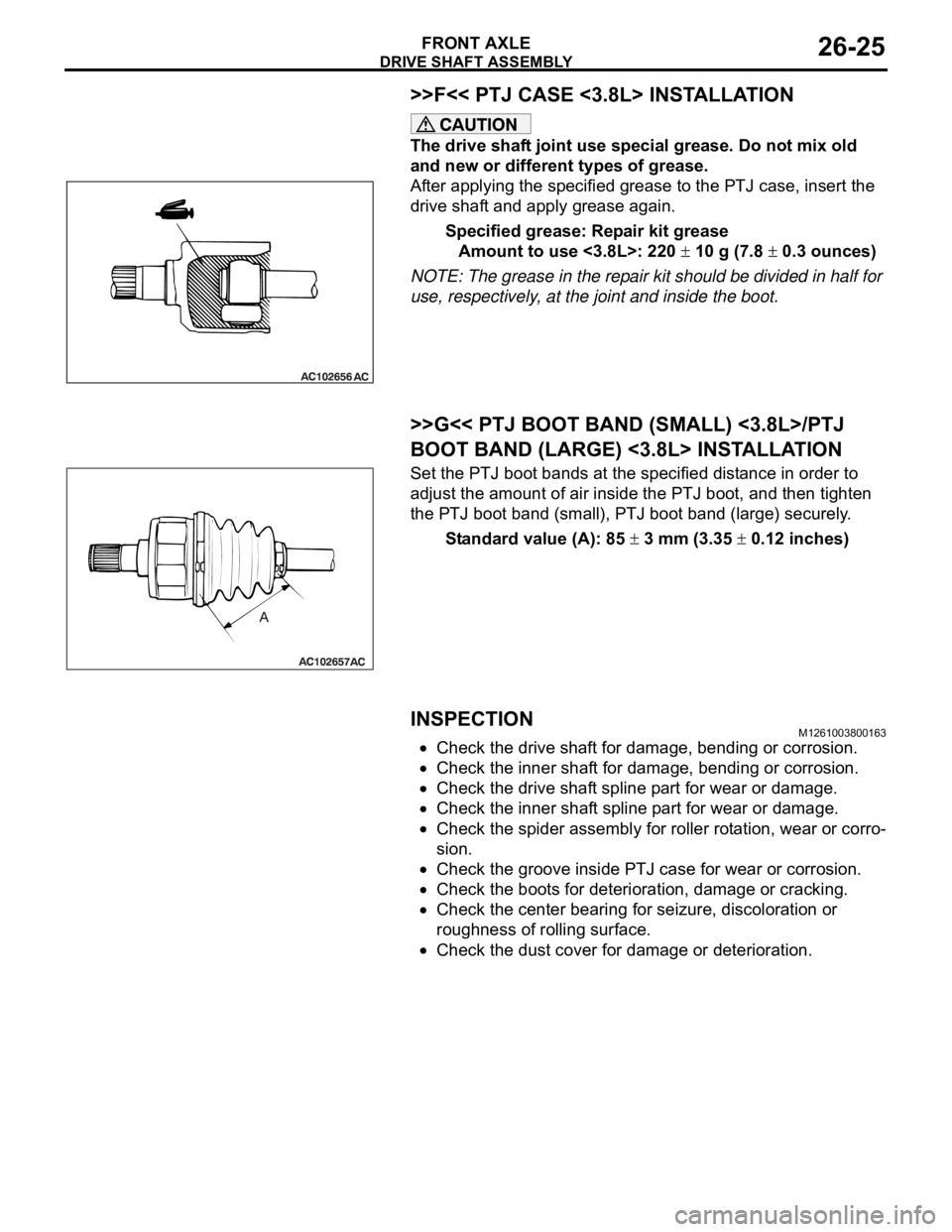
>>F<< PTJ CASE <3.8L> INSTALLATION
The drive shaft joint use special grease. Do not mix old
and new or different types of grease.
After applying the specified grease to the PTJ case, insert the
drive shaft and apply grease again.
Specified grease: Repair kit grease
Amount to use <3.8L>: 220
10 g (7.8 0.3 ounces)
NOTE: The grease in the repair kit should be divided in half for
use, respectively, at the joint and inside the boot.
.
>>G<< PTJ BOOT BAND (SMALL) <3.8L>/PTJ
BOOT BAND (LARGE) <3.8L> INSTALLATION
Set the PTJ boot bands at the specified distance in order to
adjust the amount of air inside the PTJ boot, and then tighten
the PTJ boot band (small), PTJ boot band (large) securely.
Standard value (A): 85
3 mm (3.35 0.12 inches)
INSPECTIONM1261003800163
Check the drive shaft for damage, bending or corrosion.
Check the inner shaft for damage, bending or corrosion.
Check the drive shaft spline part for wear or damage.
Check the inner shaft spline part for wear or damage.
Check the spider assembly for roller rotation, wear or corro-
sion.
Check the groove inside PTJ case for wear or corrosion.
Check the boots for deterioration, damage or cracking.
Check the center bearing for seizure, discoloration or
roughness of rolling surface.
Check the dust cover for damage or deterioration.
Page 1467 of 1500

GENERAL DESCRIPTION
AUTOMATIC TRANSMISSION23A-8
FEATURES
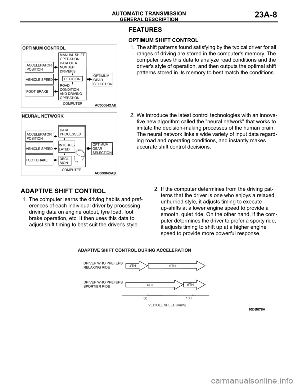
OPTIMUM SHIFT CONTROL
1. The shift patterns found satisfying by the typical driver for all
ranges of driving are stored in the computer's memory. The
computer uses this data to analyze road conditions and the
driver's style of operation, and then outputs the optimal shift
patterns stored in its memory to best match the conditions.
2. We introduce the latest control technologies with an innova-
tive new algorithm called the "neural network" that works to
imitate the decision-making processes of the human brain.
The neural network links a wide variety of input data regard-
ing road and operating conditions, and instantly makes
accurate shift control decisions.
.
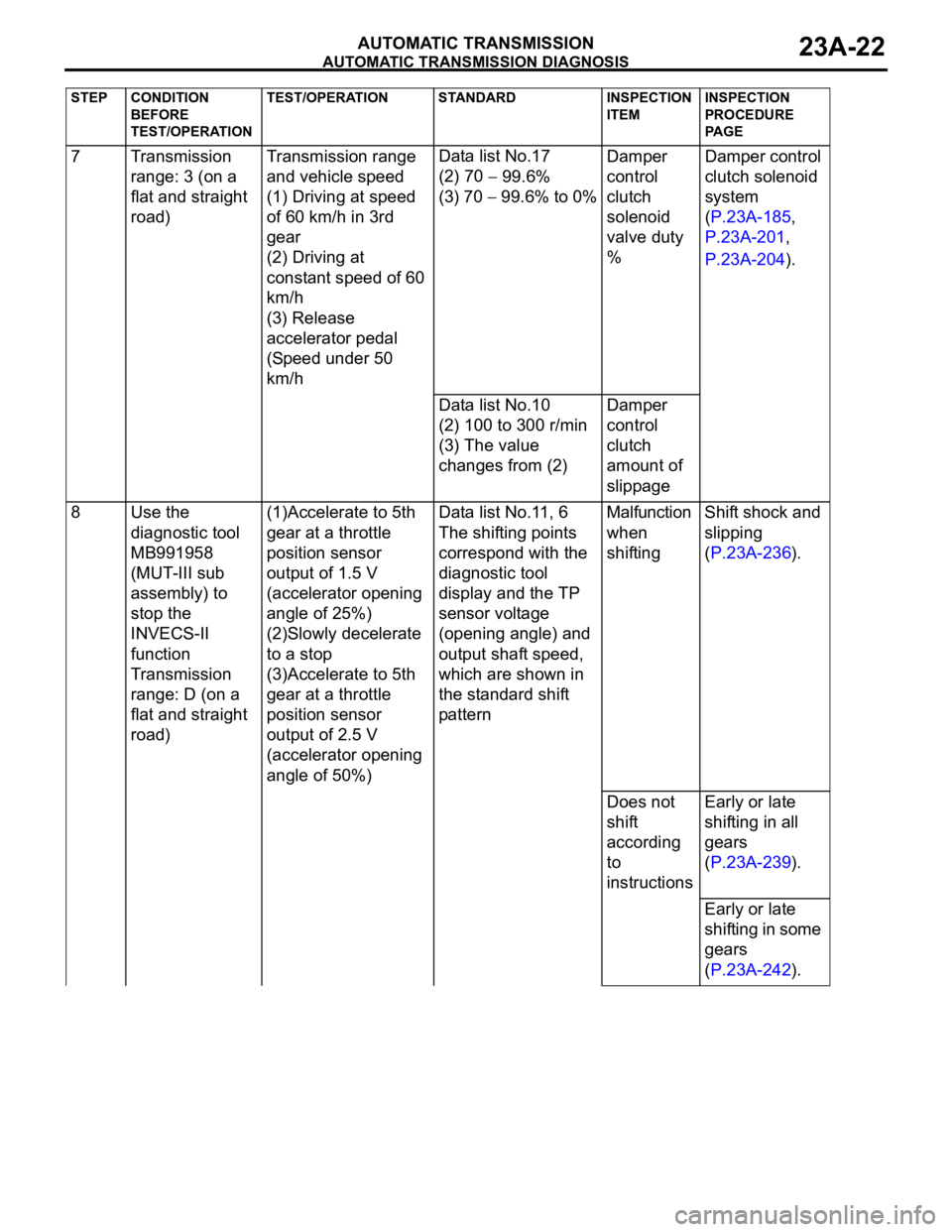
ADAPTIVE SHIFT CONTROL
1. The computer learns the driving habits and pref-
erences of each individual driver by processing
driving data on engine output, tyre load, foot
brake operation, etc. It then uses this data to
adjust shift timing to best suit the driver's style.2. If the computer determines from the driving pat-
terns that the driver is one who enjoys a relaxed,
unhurried style, it adjusts timing to execute
up-shifts at a lower engine speed to provide a
smooth, quiet ride. On the other hand, if the com-
puter determines the driver to prefer a sporty ride,
it adjusts timing to shift up at a higher engine
speed to provide more powerful response.
.
Page 1481 of 1500

AUTOMATIC TRANSMISSION DIAGNOSIS
AUTOMATIC TRANSMISSION23A-22
7 Transmission
range: 3 (on a
flat and straight
road)Transmission range
and vehicle speed
(1) Driving at speed
of 60 km/h in 3rd
gear
(2) Driving at
constant speed of 60
km/h
(3) Release
accelerator pedal
(Speed under 50
km/hData list No.17
(2) 70
99.6%
(3) 70
99.6% to 0%Damper
control
clutch
solenoid
valve duty
%Damper control
clutch solenoid
system
(P.23A-185,
P.23A-201,
P.23A-204).
Data list No.10
(2) 100 to 300 r/min
(3) The value
changes from (2)Damper
control
clutch
amount of
slippage
8 Use the
diagnostic tool
MB991958
(MUT-III sub
assembly) to
stop the
INVECS-II
function
Transmission
range: D (on a
flat and straight
road)(1)Accelerate to 5th
gear at a throttle
position sensor
output of 1.5 V
(accelerator opening
angle of 25%)
(2)Slowly decelerate
to a stop
(3)Accelerate to 5th
gear at a throttle
position sensor
output of 2.5 V
(accelerator opening
angle of 50%)Data list No.11, 6
The shifting points
correspond with the
diagnostic tool
display and the TP
sensor voltage
(opening angle) and
output shaft speed,
which are shown in
the standard shift
patternMalfunction
when
shiftingShift shock and
slipping
(P.23A-236).
Does not
shift
according
to
instructionsEarly or late
shifting in all
gears
(P.23A-239).
Early or late
shifting in some
gears
(P.23A-242).
STEP CONDITION
BEFORE
TEST/OPERATIONTEST/OPERATION STANDARD INSPECTION
ITEMINSPECTION
PROCEDURE
PA G E