2005 MITSUBISHI 380 ESP
[x] Cancel search: ESPPage 1261 of 1500
MAINTENANCE SERVICE
GENERAL00-40
The temperature of the surface of the belt should be as
close as possible to underhood temperature.
Do not let any contaminants such as water or oil get
onto the microphone.
If strong gusts of wind blow against the microphone or
if there are any loud sources of noise nearby, the val-
ues measured by the microphone may not correspond
to actual values.
If the microphone is touching the belt while the mea-
surement is being made, the values measured by the
microphone may not correspond to actual values.
Do not take the measurement while the vehicle's engine
is running.
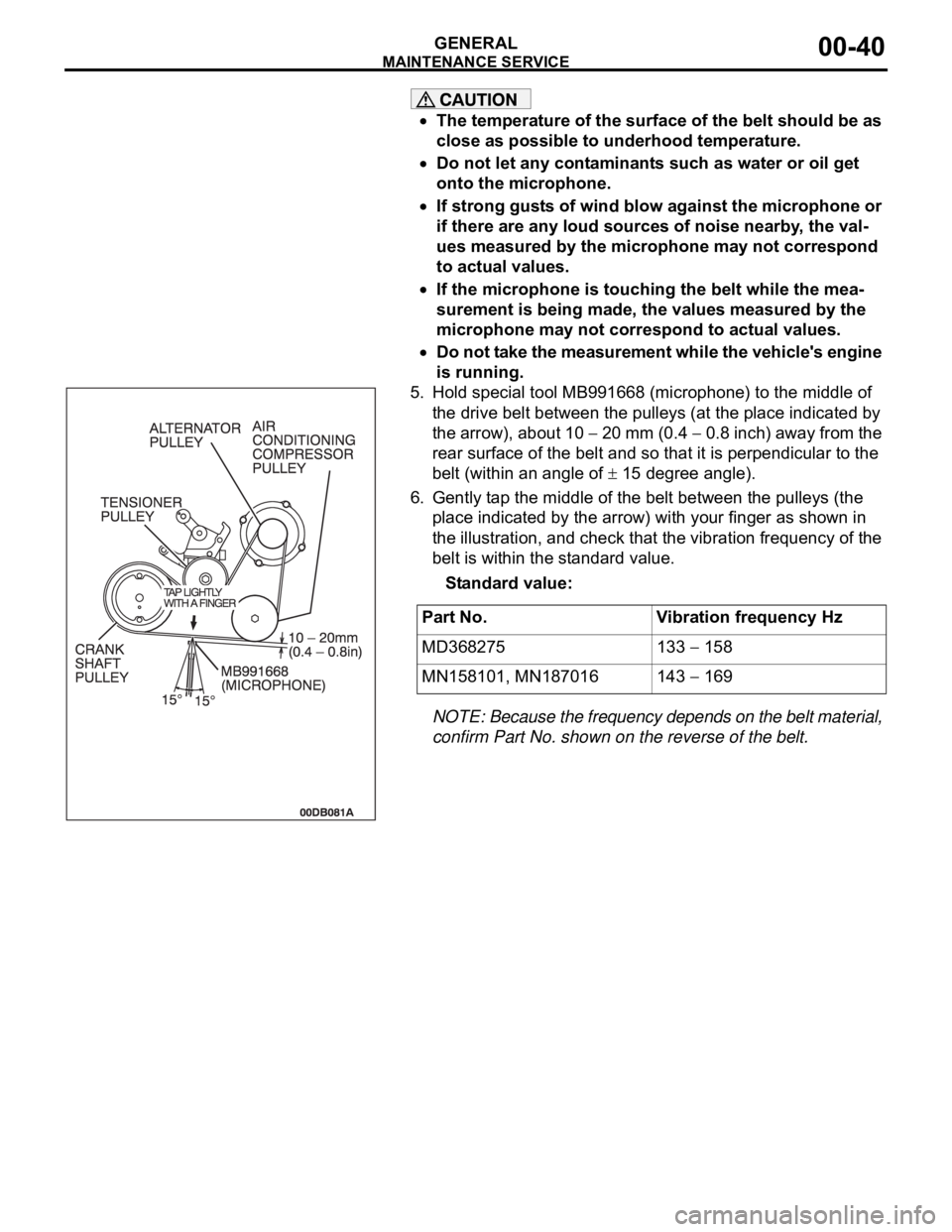
5. Hold special tool MB991668 (microphone) to the middle of
the drive belt between the pulleys (at the place indicated by
the arrow), about 10
20 mm (0.4 0.8 inch) away from the
rear surface of the belt and so that it is perpendicular to the
belt (within an angle of
15 degree angle).
6. Gently tap the middle of the belt between the pulleys (the
place indicated by the arrow) with your finger as shown in
the illustration, and check that the vibration frequency of the
belt is within the standard value.
Standard value:
NOTE: Because the frequency depends on the belt material,
confirm Part No. shown on the reverse of the belt.
.
Part No. Vibration frequency Hz
MD368275 133
158
MN158101, MN187016 143
169
Page 1282 of 1500
TRACTION CONTROL SYSTEM (TCL) DIAGNOSIS
TRACTION CONTROL SYSTEM (TCL)13C-3
TRACTION CONTROL SYSTEM (TCL) DIAGNOSIS
INTRODUCTION TO TRACTION CONTROL SYSTEM (TCL) DIAGNOSISM1136004600026
TCL Diagnostic Trouble Code Detection
Conditions
TCL diagnostic trouble codes (TCL DTCs) are set
under different conditions, depending on the mal-
function detected. Most TCL DTCs will only be set
during vehicle operation. Some TCL DTCs will also
be set during the TCL self-check immediately after
the engine is started. When you check if an TCL DTC will be displayed again after the DTC has been
erased, you should recreate the TCL DTC set condi-
tions. Depending on the detection timing and set
conditions for the specific TCL DTC, you must either
drive the vehicle or turn the engine off and restart it.
To set the proper conditions for that DTC again, refer
to "TCL DTC SET CONDITIONS" for each TCL DTC
that you are trying to reset.
TROUBLESHOOTING STRATEGYM1136003100062
Use these steps to plan your diagnostic strategy. If
you follow them carefully, you will check most of the
possible causes of a TCL problem.
1. Gather information from the customer.
2. Verify that the condition described by the
customer exists.
3. Check the vehicle for any TCL DTC. (Refer to
P.13C-3, Diagnosis Function
How to Read and
Erase Diagnostic Trouble Codes).
4. If you can verify the condition but no TCL DTCs
are set, and the malfunction may be intermittent.
(Refer to GROUP 00, How to Use
Troubleshooting/Inspection Service Points
How
to Cope with Intermittent Malfunctions P.00-14).
5. If you can verify the condition but there is no TCL
DTCs, or the system cannot communicate with
diagnostic tool MB991958 (MUT-III sub
assembly), and find the fault. (Refer to P.13C-23,
Symptom Chart).6. If there is a TCL DTC, record the number of the
code, then erase the code from vehicle memory
using the diagnostic tool MB991958 (MUT-III sub
assembly). (Refer to P.13C-3, Diagnosis Function
How to Read and Erase Diagnostic Trouble
Codes).
7. Re-create the TCL DTC set conditions to see if
the same TCL DTC will set again. (Refer to
P.13C-3, Diagnosis Function
How to Read and
Erase Diagnostic Trouble Codes).
If the same TCL DTC sets again, perform the
diagnostic procedures for the set code. (Refer to
P.13C-8, Diagnostic Trouble Code Chart).
NOTE: If the ABS-8 ECU or the active wheel
speed sensor are disconnected, or if the wir-
ing is an open/ short circuit, the ABS 8 ECU
will shut off power supply to the respective
wheel speed sensor. All other wheel speed
sensors will operate normally. To restore the
power supply, the ignition switch must be
turned to the "OFF" position then to the "ON"
position again.
DIAGNOSIS FUNCTIONM1136003200025
HOW TO CONNECT THE DIAGNOSTIC TOOL
(MUT-III)
Required Special Tools:
MB991958: Diagnostic Tool (MUT-III Sub Assembly)
MB991824: Vehicle Communication Interface (V.C.I.)
MB991827: MUT-III USB Cable
MB991910: MUT-III Main Harness A
Page 1287 of 1500
TRACTION CONTROL SYSTEM (TCL) DIAGNOSIS
TRACTION CONTROL SYSTEM (TCL)13C-8
DIAGNOSTIC TROUBLE CODE CHARTM1136003300022
During diagnosis, a DTC associated with other
system may be set when the ignition switch is
turned on with connector(s) disconnected. On
completion, confirm all systems for DTC(s). If
DTC(s) are set, erase them all.
NOTE: If the ABS-8 ECU or the active wheel
speed sensor are disconnected, or if the wiring is
an open/ short circuit, the ABS 8 ECU will shut
off power supply to the respective wheel speed
sensor. All other wheel speed sensors will oper-
ate normally. To restore the power supply, the
ignition switch must be turned to the "OFF" posi-
tion then to the "ON" position again.Follow the inspection chart that is appropriate for the
diagnostic trouble code.
DTC INSPECTION ITEM DIAGNOSTIC CONTENT REFERENCE PAGE
C1200 Front right wheel speed sensor Open circuit or short circuit GROUP 35B, ABS
Diagnosis
Diagnostic Trouble
Code Procedures
C1200 P.35B-10
C1201 Front right wheel speed sensor Abnormal output signal GROUP 35B, ABS
Diagnosis
Diagnostic Trouble
Code Procedures
C1201 P.35B-26
C1205 Front left wheel speed sensor Open circuit or short circuitGROUP 35B, ABS
Diagnosis
Diagnostic Trouble
Code Procedures
C1205 P.35B-10
C1206 Front left wheel speed sensor Abnormal output signal GROUP 35B, ABS
Diagnosis
Diagnostic Trouble
Code Procedures
C1206 P.35B-26
C1210 Rear right wheel speed sensor Open circuit or short circuitGROUP 35B, ABS
Diagnosis
Diagnostic Trouble
Code Procedures
C1210 P.35B-10
C1211 Rear right wheel speed sensor Abnormal output signal GROUP 35B, ABS
Diagnosis
Diagnostic Trouble
Code Procedures
C1211 P.35B-26
C1215 Rear left wheel speed sensor Open circuit or short circuit GROUP 35B, ABS
Diagnosis
Diagnostic Trouble
Code Procedures
C1215 P.35B-10
Page 1289 of 1500
TRACTION CONTROL SYSTEM (TCL) DIAGNOSIS
TRACTION CONTROL SYSTEM (TCL)13C-10
NOTE: Since the TCL is controlled with the same ABS/TCL-ECU used to control the ABS, the codes (with a
*) used only for the ABS also appear.
The inspection contents for the codes (with a *) used only for the ABS do not described in this group.
DIAGNOSTIC TROUBLE CODE PROCEDURES
U1100 CAN Communications System Time Out Error Engine Related Data
If DTC U1100 is set in the ABS/TCL-ECU,
always diagnose the CAN main bus line. If
there is any fault in the CAN bus lines, an
incorrect DTC may be set.
Whenever the ABS/TCL-ECU is replaced,
ensure that the communication circuit is nor-
mal.
NOTE: If the ABS-8 ECU or the active wheel
speed sensor are disconnected, or if the wiring is
an open/ short circuit, the ABS 8 ECU will shut
off power supply to the respective wheel speed
sensor. All other wheel speed sensors will oper-
ate normally. To restore the power supply, the
ignition switch must be turned to the "OFF" posi-
tion then to the "ON" position again.
.
DTC SET CONDITION
The ABS/TCL-ECU receives engine system-related
signals from the ENGINE-ECU via CAN bus lines.
.
TROUBLESHOOTING HINTS (THE MOST
LIKELY CAUSES FOR THESE DTCS ARE
TO SET ARE:)
Damaged harness or connector.
Malfunction of the ENGINE-ECU.
Malfunction of the ABS/TCL-ECU.
DIAGNOSIS
Required Special Tools:
MB991958: Diagnostic Tool (MUT-III Sub Assembly)
MB991824: V.C.I.
MB991827: MUT-III USB Cable
MB991910: MUT-III Main Harness A U1073 CAN communications system bus off GROUP 35B, ABS
Diagnosis
Diagnostic Trouble
Code Procedures
U1073 P.35B-68
U1100 CAN communications system time out error engine related data
P.13C-10
U1101 CAN communications system time out error A/T related data
P.13C-14
U1400 Dynamic range error APS1
P.13C-22
U1415 CAN invalid signal Gear Position GROUP 23A
Diagnostic Trouble
Code Chart P.23A-34 DTC INSPECTION ITEM DIAGNOSTIC CONTENT REFERENCE PAGE
Page 1293 of 1500
TRACTION CONTROL SYSTEM (TCL) DIAGNOSIS
TRACTION CONTROL SYSTEM (TCL)13C-14
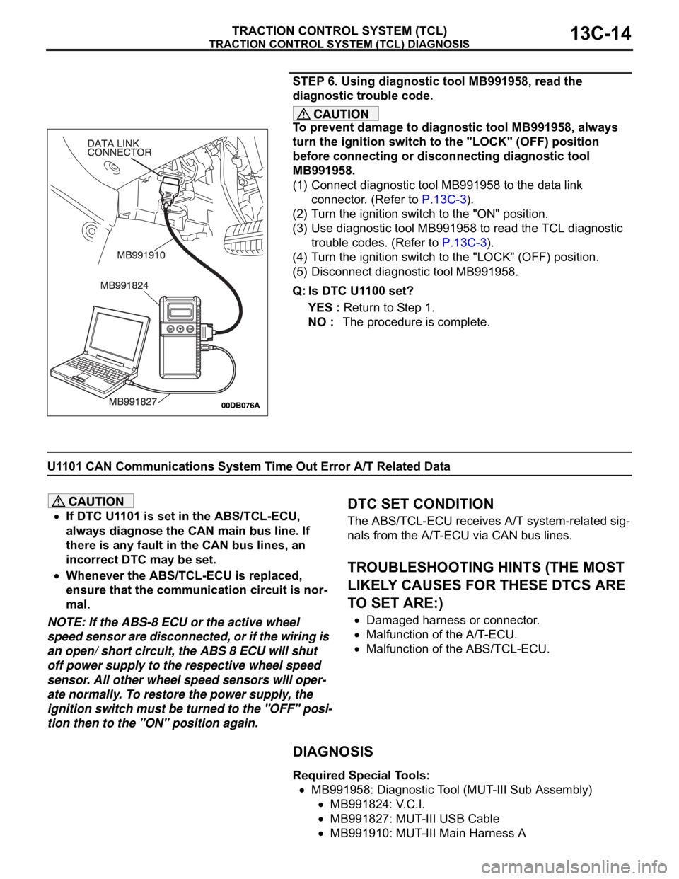
STEP 6. Using diagnostic tool MB991958, read the
diagnostic trouble code.
To prevent damage to diagnostic tool MB991958, always
turn the ignition switch to the "LOCK" (OFF) position
before connecting or disconnecting diagnostic tool
MB991958.
(1) Connect diagnostic tool MB991958 to the data link
connector. (Refer to P.13C-3).
(2) Turn the ignition switch to the "ON" position.
(3) Use diagnostic tool MB991958 to read the TCL diagnostic
trouble codes. (Refer to P.13C-3).
(4) Turn the ignition switch to the "LOCK" (OFF) position.
(5) Disconnect diagnostic tool MB991958.
Q: Is DTC U1100 set?
YES : Return to Step 1.
NO : The procedure is complete.
U1101 CAN Communications System Time Out Error A/T Related Data
If DTC U1101 is set in the ABS/TCL-ECU,
always diagnose the CAN main bus line. If
there is any fault in the CAN bus lines, an
incorrect DTC may be set.
Whenever the ABS/TCL-ECU is replaced,
ensure that the communication circuit is nor-
mal.
NOTE: If the ABS-8 ECU or the active wheel
speed sensor are disconnected, or if the wiring is
an open/ short circuit, the ABS 8 ECU will shut
off power supply to the respective wheel speed
sensor. All other wheel speed sensors will oper-
ate normally. To restore the power supply, the
ignition switch must be turned to the "OFF" posi-
tion then to the "ON" position again.
.
DTC SET CONDITION
The ABS/TCL-ECU receives A/T system-related sig-
nals from the A/T-ECU via CAN bus lines.
.
TROUBLESHOOTING HINTS (THE MOST
LIKELY CAUSES FOR THESE DTCS ARE
TO SET ARE:)
Damaged harness or connector.
Malfunction of the A/T-ECU.
Malfunction of the ABS/TCL-ECU.
DIAGNOSIS
Required Special Tools:
MB991958: Diagnostic Tool (MUT-III Sub Assembly)
MB991824: V.C.I.
MB991827: MUT-III USB Cable
MB991910: MUT-III Main Harness A
Page 1297 of 1500
TRACTION CONTROL SYSTEM (TCL) DIAGNOSIS
TRACTION CONTROL SYSTEM (TCL)13C-18
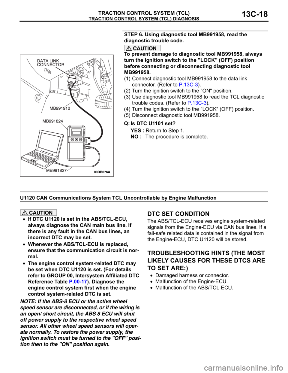
STEP 6. Using diagnostic tool MB991958, read the
diagnostic trouble code.
To prevent damage to diagnostic tool MB991958, always
turn the ignition switch to the "LOCK" (OFF) position
before connecting or disconnecting diagnostic tool
MB991958.
(1) Connect diagnostic tool MB991958 to the data link
connector. (Refer to P.13C-3).
(2) Turn the ignition switch to the "ON" position.
(3) Use diagnostic tool MB991958 to read the TCL diagnostic
trouble codes. (Refer to P.13C-3).
(4) Turn the ignition switch to the "LOCK" (OFF) position.
(5) Disconnect diagnostic tool MB991958.
Q: Is DTC U1101 set?
YES : Return to Step 1.
NO : The procedure is complete.
U1120 CAN Communications System TCL Uncontrollable by Engine Malfunction
If DTC U1120 is set in the ABS/TCL-ECU,
always diagnose the CAN main bus line. If
there is any fault in the CAN bus lines, an
incorrect DTC may be set.
Whenever the ABS/TCL-ECU is replaced,
ensure that the communication circuit is nor-
mal.
The engine control system-related DTC may
be set when DTC U1120 is set. (For details
refer to GROUP 00, Intersystem Affiliated DTC
Reference Table P.00-17). Diagnose the
engine control system first when the engine
control system-related DTC is set.
NOTE: If the ABS-8 ECU or the active wheel
speed sensor are disconnected, or if the wiring is
an open/ short circuit, the ABS 8 ECU will shut
off power supply to the respective wheel speed
sensor. All other wheel speed sensors will oper-
ate normally. To restore the power supply, the
ignition switch must be turned to the "OFF" posi-
tion then to the "ON" position again.
.
DTC SET CONDITION
The ABS/TCL-ECU receives engine system-related
signals from the Engine-ECU via CAN bus lines. If a
fail-safe related data is contained in the signal from
the Engine-ECU, DTC U1120 will be stored.
.
TROUBLESHOOTING HINTS (THE MOST
LIKELY CAUSES FOR THESE DTCS ARE
TO SET ARE:)
Damaged harness or connector.
Malfunction of the Engine-ECU.
Malfunction of the ABS/TCL-ECU.
Page 1304 of 1500

TRACTION CONTROL SYSTEM (TCL) DIAGNOSIS
TRACTION CONTROL SYSTEM (TCL)13C-25
NOTE: If you press the TCL switch to deactivate the
TCL and then keep the TCL switch pressed for about
10 seconds, an error prevention function will auto-
matically reactivate the TCL. If you then still wish to
deactivate the TCL, press the TCL switch again to
deactivate it.NOTE: If the ABS-8 ECU or the active wheel
speed sensor are disconnected, or if the wiring is
an open/ short circuit, the ABS 8 ECU will shut
off power supply to the respective wheel speed
sensor. All other wheel speed sensors will oper-
ate normally. To restore the power supply, the
ignition switch must be turned to the "OFF" posi-
tion then to the "ON" position again.
.
Page 1307 of 1500
TRACTION CONTROL SYSTEM (TCL) DIAGNOSIS
TRACTION CONTROL SYSTEM (TCL)13C-28
STEP 4. Retest the system
Q: Turn the ignition switch to the "ON" position. Do the
"TCL OFF" indicator light and the TCL work indicator
light illuminate for three seconds, and then go out after
the engine starts?
YES : The procedure is complete.
NO : . Return to Step 1.
INSPECTION PROCEDURE 5: When the TCL Switch is Pushed On, TCL does not Cancel.
NOTE: If the ABS-8 ECU or the active wheel
speed sensor are disconnected, or if the wiring is
an open/ short circuit, the ABS 8 ECU will shut
off power supply to the respective wheel speed
sensor. All other wheel speed sensors will oper-
ate normally. To restore the power supply, the
ignition switch must be turned to the "OFF" posi-
tion then to the "ON" position again.
.
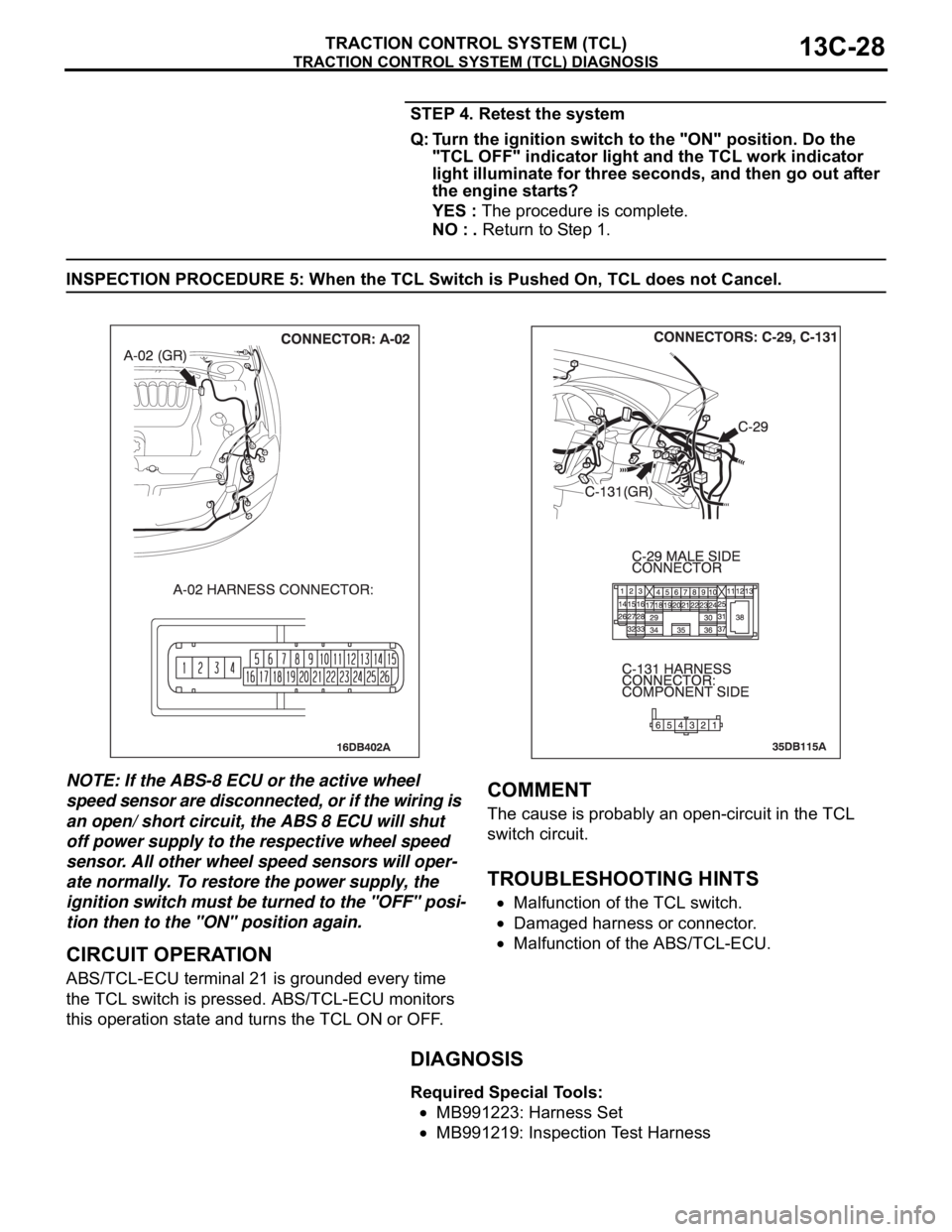
CIRCUIT OPERATION
ABS/TCL-ECU terminal 21 is grounded every time
the TCL switch is pressed. ABS/TCL-ECU monitors
this operation state and turns the TCL ON or OFF.
.
COMMENT
The cause is probably an open-circuit in the TCL
switch circuit.
.
TROUBLESHOOTING HINTS
Malfunction of the TCL switch.
Damaged harness or connector.
Malfunction of the ABS/TCL-ECU.
DIAGNOSIS
Required Special Tools:
MB991223: Harness Set
MB991219: Inspection Test Harness