Page 1014 of 1500
IGNITION SYSTEM
ENGINE ELECTRICAL16-37
INSTALLATION SERVICE POINT
.
>>A<< KNOCK SENSOR INSTALLATION
Use special tool MD998773 to install the knock sensor.
Page 1015 of 1500

SPECIFICATIONS
ENGINE ELECTRICAL16-38
SPECIFICATIONS
FASTENER TIGHTENING SPECIFICATIONSM1161002100506
GENERAL SPECIFICATIONSM1161000200411
ITEM SPECIFICATION
Charging system
Alternator bracket bolt49
9 Nm (36 7 ft-lb)
Alternator bolt49
9 Nm (36 7 ft-lb)
Alternator terminal nut12
2 Nm (102 22 in-lb)
Ignition system
Camshaft position sensor bolt 11
1 Nm (98 8 in-lb)
Crankshaft position sensor bolt 9.0
1.0 Nm (80 9 in-lb)
Ignition coil bolt 10
2 Nm (89 17 in-lb)
Knock sensor 23
2 Nm (17 1 ft-lb)
Spark plug 25
4 Nm (18 3 ft-lb)
Starting system
Starter bolt 30
3 Nm (23 2 ft-lb)
Starter cover bolt 4.9
1.0 Nm (44 8 in-lb)
Starter terminal nut 12
2 Nm (102 22 in-lb)
ITEMS SPECIFICATIONS
Alternator
Type Positive battery positive voltage sensing
Identification number
Part No. MN180394
Rated output V/A 12/110
Voltage regulator Electronic built-in type
Starter Motor
Type Reduction drive with planetary gear
Identification number M000T31172
Part No. 1810A090
Rated output kW/V 1.2/12
Number of pinion teeth 8
Ignition Coil
Type Molded 6 coil
Spark Plugs
BOSCH FR8DI30
Page 1016 of 1500
SPECIFICATIONS
ENGINE ELECTRICAL16-39
SERVICE SPECIFICATIONSM1161000300322
ITEMS STANDARD VALUE LIMIT
Alternator
Regulated voltage
(Ambient temperature at voltage
regulator)
20C (4F)14.2 15.4
20C (68F) 13.9 14.9
60C (140F) 13.4 14.5
80C (176F) 13.1 14.5
Alternator output wire voltage drop (at 30 A) VMaximum 0.3
Nominal Output current 110A 70 % of normal output
current
Field coil resistance
Approximately 2 5
Brush protrusion length mm (in)Minimum 2 (0.08)
Starter motor
Free running characteristics Terminal voltage
V11
Current A 95
Speed r/min 2,500 or more
Pinion gap mm (in) 0.5 2.0 (0.02 0.07)
Commutator run-out mm (in) 0.05 (0.002) Minimum 0.1 (0.004)
Commutator diameter mm (in) 29.4 (1.16) Minimum 28.8 (1.13)
Undercut depth mm (in) 0.5 (0.02) Minimum 0.2 (0.008)
Ignition parts
Spark plug gap mm 1.0 1.1
Page 1017 of 1500
SPECIFICATIONS
ENGINE ELECTRICAL16-40
Page 1018 of 1500
32-1
GROUP 32
POWER PLANT
MOUNT
CONTENTS
GENERAL DESCRIPTION. . . . . . . . .32-2
SPECIAL TOOL . . . . . . . . . . . . . . . . .32-3
ENGINE MOUNTING . . . . . . . . . . . . .32-4
REMOVAL AND INSTALLATION . . . . . . . . 32-4
TRANSAXLE MOUNTING . . . . . . . . .32-5
REMOVAL AND INSTALLATION . . . . . . . . 32-5
ENGINE ROLL STOPPER AND
CENTREMEMBER . . . . . . . . . . . . . . .32-7
REMOVAL AND INSTALLATION . . . . . . . . 32-7
CROSSMEMBER . . . . . . . . . . . . . . . .32-9
REMOVAL AND INSTALLATION . . . . . . . . 32-9
INSPECTION. . . . . . . . . . . . . . . . . . . . . . . . 32-14
SPECIFICATIONS . . . . . . . . . . . . . . .32-15
FASTENER TIGHTENING
SPECIFICATIONS. . . . . . . . . . . . . . . . . . . . 32-15
Page 1019 of 1500
GENERAL DESCRIPTION
POWER PLANT MOUNT32-2
GENERAL DESCRIPTIONM1321000100373
The engine front mounting bracket is a
dome-shaped fluid-filled mount for improved
responsiveness during acceleration and more
stable vehicle performance against road distur-
bances.The liquid-filled transaxle mounting body side
bracket improves riding comfort by its refined
insulator.
A roll stopper bracket in the upper area limits
engine rolling. Furthermore, large diameter insu-
lator reduces idle vibration.
CONSTRUCTION DIAGRAM
Page 1021 of 1500
ENGINE MOUNTING
POWER PLANT MOUNT32-4
ENGINE MOUNTING
REMOVAL AND INSTALLATIONM1321001100462
*: Indicates parts which should be initially tightened, and then fully tightened after placing the vehicle
horizontally and loading the full weight of the engine on the vehicle body.
Pre-removal Operation
Raise the engine and transaxle assembly until its weight is
not applied to the insulator, and support it securely.
REMOVAL STEPS
2. ENGINE MOUNTING STAY
3. MOUNTING BOLT
4. SELF LOCKING NUTS5. ENGINE MOUNT BRACKET
6. ENGINE MOUNT STOPPER
7. DYNAMIC DAMPERREMOVAL STEPS (Continued)
Page 1022 of 1500

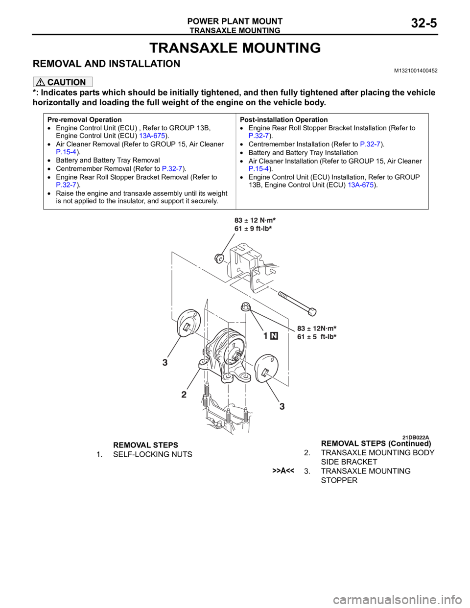
TRANSAXLE MOUNTING
POWER PLANT MOUNT32-5
TRANSAXLE MOUNTING
REMOVAL AND INSTALLATIONM1321001400452
*: Indicates parts which should be initially tightened, and then fully tightened after placing the vehicle
horizontally and loading the full weight of the engine on the vehicle body.
Pre-removal Operation
Engine Control Unit (ECU) , Refer to GROUP 13B,
Engine Control Unit (ECU) 13A-675).
Air Cleaner Removal (Refer to GROUP 15, Air Cleaner
P.15-4).
Battery and Battery Tray Removal
Centremember Removal (Refer to P.32-7).
Engine Rear Roll Stopper Bracket Removal (Refer to
P.32-7).
Raise the engine and transaxle assembly until its weight
is not applied to the insulator, and support it securely.Post-installation Operation
Engine Rear Roll Stopper Bracket Installation (Refer to
P.32-7).
Centremember Installation (Refer to P.32-7).
Battery and Battery Tray Installation
Air Cleaner Installation (Refer to GROUP 15, Air Cleaner
P.15-4).
Engine Control Unit (ECU) Installation, Refer to GROUP
13B, Engine Control Unit (ECU) 13A-675).
REMOVAL STEPS
1. SELF-LOCKING NUTS2. TRANSAXLE MOUNTING BODY
SIDE BRACKET
>>A<<3. TRANSAXLE MOUNTING
STOPPER REMOVAL STEPS (Continued)