Page 1024 of 1500
ENGINE ROLL STOPPER AND CENTREMEMBER
POWER PLANT MOUNT32-7
ENGINE ROLL STOPPER AND CENTREMEMBER
REMOVAL AND INSTALLATIONM1321002300306
*: Indicates parts which should be initially tightened, and then fully tightened after placing the vehicle
horizontally and loading the full weight of the engine on the vehicle body.
Pre-removal and Post-installation Operation
Side Under Cover Removal and Installation (Refer to
GROUP 51, Under Cover P.51-13).
FRONT ROLL STOPPER AND
CENTREMEMBER REMOVAL
STEPS
1. SELF-LOCKING NUT
2. ENGINE FRONT ROLL STOPPER
BRACKET AND
CENTREMEMBER
>>B<<3. ENGINE FRONT ROLL STOPPER
BRACKET
4.
CENTREMEMBERREAR ROLL STOPPER
REMOVAL STEPS
FRONT AXLE NO.1
CROSSMEMBER ASSEMBLY
(REFER TO P.32-9).
5. ENGINE REAR ROLL STOPPER
BRACKET
REAR ROLL STOPPER
BRACKET REMOVAL STEPS
FRONT NO.1 EXHAUST PIPE
(REFER TO GROUP 15,
EXHAUST PIPE AND MAIN
MUFFLER P.15-14).
1. SELF-LOCKING NUT
Page 1025 of 1500
ENGINE ROLL STOPPER AND CENTREMEMBER
POWER PLANT MOUNT32-8
INSTALLATION SERVICE POINTS
.
>>B<< ENGINE FRONT ROLL STOPPER
BRACKET INSTALLATION
Install the engine front roll stopper bracket so that its hole
points towards the front side of the vehicle.
2. ENGINE FRONT ROLL STOPPER
BRACKET AND
CENTREMEMBER
6. SELF-LOCKING NUT
7. TRANSAXLE CASE REAR ROLL
STOPPER BRACKET REAR ROLL STOPPER
BRACKET REMOVAL STEPS
Page 1026 of 1500

CROSSMEMBER
POWER PLANT MOUNT32-9
CROSSMEMBER
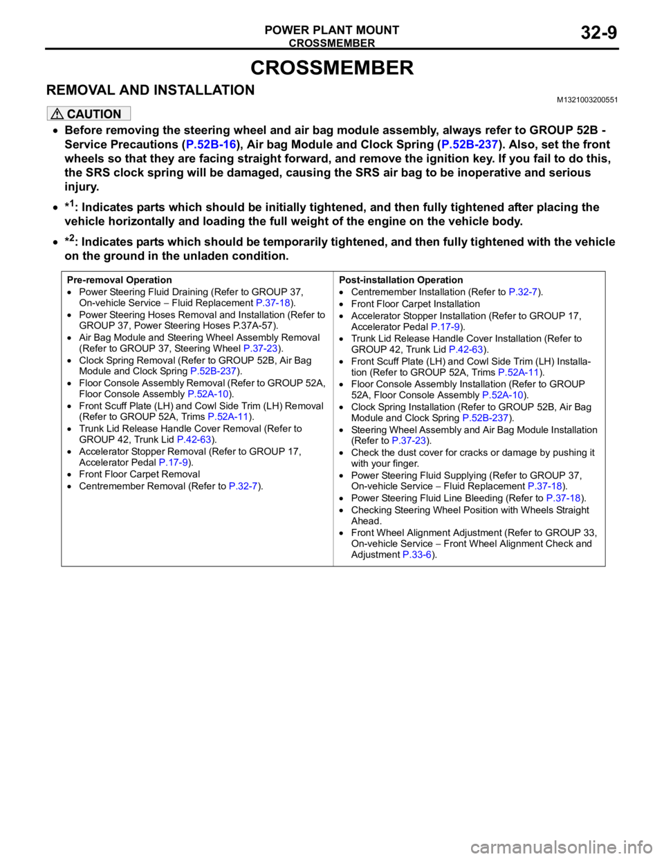
REMOVAL AND INSTALLATIONM1321003200551
Before removing the steering wheel and air bag module assembly, always refer to GROUP 52B -
Service Precautions (P.52B-16), Air bag Module and Clock Spring (P.52B-237). Also, set the front
wheels so that they are facing straight forward, and remove the ignition key. If you fail to do this,
the SRS clock spring will be damaged, causing the SRS air bag to be inoperative and serious
injury.
*1: Indicates parts which should be initially tightened, and then fully tightened after placing the
vehicle horizontally and loading the full weight of the engine on the vehicle body.
*2: Indicates parts which should be temporarily tightened, and then fully tightened with the vehicle
on the ground in the unladen condition.
Pre-removal Operation
Power Steering Fluid Draining (Refer to GROUP 37,
On-vehicle Service Fluid Replacement P.37-18).
Power Steering Hoses Removal and Installation (Refer to
GROUP 37, Power Steering Hoses P.37A-57).
Air Bag Module and Steering Wheel Assembly Removal
(Refer to GROUP 37, Steering Wheel P.37-23).
Clock Spring Removal (Refer to GROUP 52B, Air Bag
Module and Clock Spring P.52B-237).
Floor Console Assembly Removal (Refer to GROUP 52A,
Floor Console Assembly P.52A-10).
Front Scuff Plate (LH) and Cowl Side Trim (LH) Removal
(Refer to GROUP 52A, Trims P.52A-11).
Trunk Lid Release Handle Cover Removal (Refer to
GROUP 42, Trunk Lid P.42-63).
Accelerator Stopper Removal (Refer to GROUP 17,
Accelerator Pedal P.17-9).
Front Floor Carpet Removal
Centremember Removal (Refer to P.32-7).Post-installation Operation
Centremember Installation (Refer to P.32-7).
Front Floor Carpet Installation
Accelerator Stopper Installation (Refer to GROUP 17,
Accelerator Pedal P.17-9).
Trunk Lid Release Handle Cover Installation (Refer to
GROUP 42, Trunk Lid P.42-63).
Front Scuff Plate (LH) and Cowl Side Trim (LH) Installa-
tion (Refer to GROUP 52A, Trims P.52A-11).
Floor Console Assembly Installation (Refer to GROUP
52A, Floor Console Assembly P.52A-10).
Clock Spring Installation (Refer to GROUP 52B, Air Bag
Module and Clock Spring P.52B-237).
Steering Wheel Assembly and Air Bag Module Installation
(Refer to P.37-23).
Check the dust cover for cracks or damage by pushing it
with your finger.
Power Steering Fluid Supplying (Refer to GROUP 37,
On-vehicle Service Fluid Replacement P.37-18).
Power Steering Fluid Line Bleeding (Refer to P.37-18).
Checking Steering Wheel Position with Wheels Straight
Ahead.
Front Wheel Alignment Adjustment (Refer to GROUP 33,
On-vehicle Service
Front Wheel Alignment Check and
Adjustment P.33-6).
Page 1027 of 1500
Page 1030 of 1500
CROSSMEMBER
POWER PLANT MOUNT32-13
<> FRONT AXLE CROSSMEMBER
MOUNTING BOLT REMOVAL
Remove the crossmember mounting bolt.
.
<> ENGINE REAR ROLL STOPPER BRACKET,
POWER STEERING GEAR AND LINKAGE,
STABILIZER BAR AND FRONT AXLE NO.1
CROSSMEMBER ASSEMBLY REMOVAL
Support the front axle number 1 crossmember with a transmis-
sion jack, and then remove the crossmember mounting nuts
and bolts.
INSTALLATION SERVICE POINTS
.
>>A<< STABILIZER BAR INSTALLATION
Align the stabilizer bar identification mark with the right end of
the bushing (LH).
.
Page 1032 of 1500

SPECIFICATIONS
POWER PLANT MOUNT32-15
SPECIFICATIONS
FASTENER TIGHTENING SPECIFICATIONSM1321004100308
ITEM SPECIFICATION
Crossmember
Engine rear roll stopper bracket bolt 58
7 Nm
Front axle crossmember stay bolt and nut 83
12 Nm (61 9 ft-lb)
Front axle No.1 crossmember bolt and nut 180
20 Nm (133 15 ft-lb)
Lower arm assembly bolt 165
15 Nm (122 11 ft-lb)
Lower arm assembly nut (flange nut, self-locking) M14 165
15 Nm (122 11 ft-lb)
Lower arm ball joint clamp assembly nut 110
10 Nm
Power steering gear and linkage bolt 83
12 Nm (61 9 ft-lb)
Power steering gear bracket bolt M12 83
12 Nm (61 9 ft-lb)
Pressure hose clamp bolt and nut 12
2 Nm (102 22 in-lb)
Pressure hose nut 15
3 Nm (11 2 ft-lb)
Return tube clamp bolt and nut 12
2 Nm (102 22 in-lb)
Return tube nut 15
3 Nm (11 2 ft-lb)
Stabilizer bracket bolt 58
7 Nm (43 5 ft-lb)
Stabilizer link nut 48
7 Nm (36 5 ft-lb)
Steering column assembly bolt 18
2 Nm (13 2 ft-lb)
Steering gear and linkage protector bolt 12
2 Nm (102 22 in-lb)
Tie rod end nut 29
4 Nm (21 3 ft-lb)
Engine mounting
Engine mounting thru bolt M12 108
10 Nm (80 9 ft-lb)
Engine front mounting bracket bolt and nut M12 108
10 Nm (80 9 ft-lb)
Engine mounting stay bolt 36
6 Nm (27 4 ft-lb)
Engine roll stopper and centremember
Centremember bolt83
12 Nm (61 9 ft-lb)
Engine front roll stopper thru bolt and nut 69
10 Nm (61 9 ft-lb
Engine rear roll stopper thru bolt and nut 69
10 Nm (61 9 ft-lb
Transaxle case rear roll stopper bracket bolt 90
10 Nm (67 7 ft-lb)
Transaxle mounting
Transaxle mounting body side bracket nut (nut, flange) M12 83
12 Nm (61 9 ft-lb)
Transaxle mounting body side bracket nut (nut, self-locking) M1283
12 Nm (61 9 ft-lb)
Page 1040 of 1500
GARNISHES AND MOLDINGS
EXTERIOR51-7
1. Open the engine hood and remove the 6 attaching scrivets
from the top edge of grille.
2. Using Special Tool MB990784 or similar. Insert the tool
between the top surface of the bumper and lower edge of
the grille at each clipping point and release grille lower side.
3. Carefully remove the grille from bumper and avoid any paint
damage.
GARNISHES AND MOLDINGS
SPECIAL TOOLSM1511000601158
TOOL TOOL NUMBER AND
NAMESUPERSESSION APPLICATION
MB990784 Ornament
removerGeneral service tool Side protector molding
Roof drip molding
Page 1169 of 1500

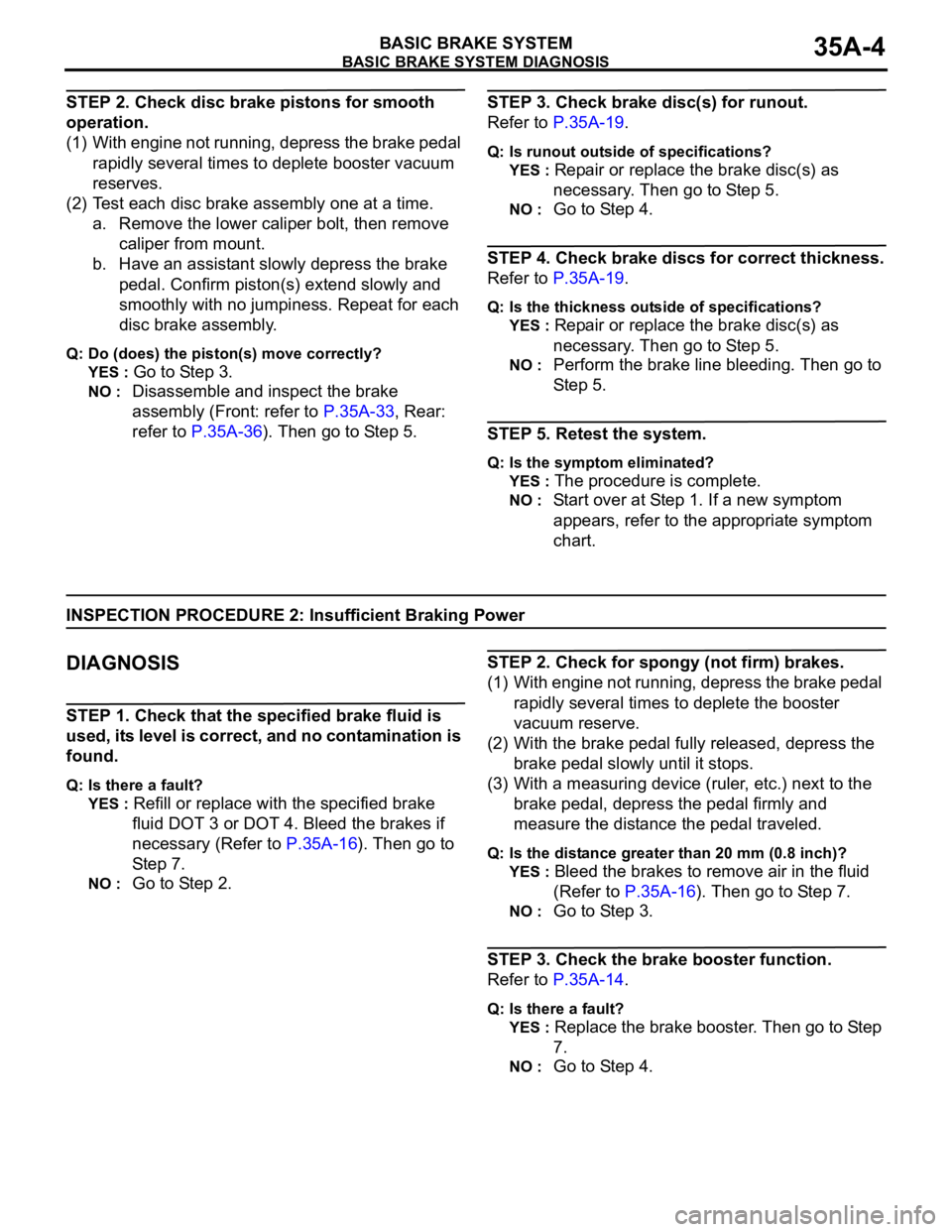
BASIC BRAKE SYSTEM DIAGNOSIS
BASIC BRAKE SYSTEM35A-4
STEP 2. Check disc brake pistons for smooth
operation.
(1) With engine not running, depress the brake pedal
rapidly several times to deplete booster vacuum
reserves.
(2) Test each disc brake assembly one at a time.
a. Remove the lower caliper bolt, then remove
caliper from mount.
b. Have an assistant slowly depress the brake
pedal. Confirm piston(s) extend slowly and
smoothly with no jumpiness. Repeat for each
disc brake assembly.
Q: Do (does) the piston(s) move correctly?
YES :
Go to Step 3.
NO : Disassemble and inspect the brake
assembly (Front: refer to P.35A-33, Rear:
refer to P.35A-36). Then go to Step 5.
STEP 3. Check brake disc(s) for runout.
Refer to P.35A-19.
Q: Is runout outside of specifications?
YES :
Repair or replace the brake disc(s) as
necessary. Then go to Step 5.
NO : Go to Step 4.
STEP 4. Check brake discs for correct thickness.
Refer to P.35A-19.
Q: Is the thickness outside of specifications?
YES :
Repair or replace the brake disc(s) as
necessary. Then go to Step 5.
NO : Perform the brake line bleeding. Then go to
St e p 5.
STEP 5. Retest the system.
Q: Is the symptom eliminated?
YES :
The procedure is complete.
NO : Start over at Step 1. If a new symptom
appears, refer to the appropriate symptom
chart.
INSPECTION PROCEDURE 2: Insufficient Braking Power
.
DIAGNOSIS
STEP 1. Check that the specified brake fluid is
used, its level is correct, and no contamination is
found.
Q: Is there a fault?
YES :
Refill or replace with the specified brake
fluid DOT 3 or DOT 4. Bleed the brakes if
necessary (Refer to P.35A-16). Then go to
Step 7.
NO : Go to Step 2.
STEP 2. Check for spongy (not firm) brakes.
(1) With engine not running, depress the brake pedal
rapidly several times to deplete the booster
vacuum reserve.
(2) With the brake pedal fully released, depress the
brake pedal slowly until it stops.
(3) With a measuring device (ruler, etc.) next to the
brake pedal, depress the pedal firmly and
measure the distance the pedal traveled.
Q: Is the distance greater than 20 mm (0.8 inch)?
YES :
Bleed the brakes to remove air in the fluid
(Refer to P.35A-16). Then go to Step 7.
NO : Go to Step 3.
STEP 3. Check the brake booster function.
Refer to P.35A-14.
Q: Is there a fault?
YES :
Replace the brake booster. Then go to Step
7.
NO : Go to Step 4.