2005 MITSUBISHI 380 engine
[x] Cancel search: enginePage 1224 of 1500
HOW TO USE THIS MANUAL
GENERAL00-3
HOW TO USE THIS MANUALM1001000100897
MAINTENANCE, REPAIR AND
SERVICING EXPLANATIONS
This manual provides explanations, etc. concerning
procedures for the inspection, maintenance, repair
and servicing of the subject model. Unless otherwise
specified, each service procedure covers all models.
Procedures covering specific models are identified
by the model codes, or similar designation (engine
type, transaxle type, etc). A description of these des-
ignations is covered in this manual under "VEHICLE
IDENTIFICATION."
.
ON-VEHICLE SERVICE
The "ON-VEHICLE SERVICE" section has proce-
dures for performing inspections and adjustments of
particularly important components. These proce-
dures are done with regard to maintenance and ser-
vicing, but other inspections (looseness, play,
cracking, damage, etc.) must also be performed.
.
SERVICE PROCEDURES
The service steps are arranged in numerical order.
Attention to be paid in performing vehicle service are
described in detail in SERVICE POINTS.
DEFINITION OF TERMS
.
STANDARD VALUE
Indicates the value used as the standard for judging
whether or not a part or adjustment is correct.
.
LIMIT
Shows the maximum or minimum value for judging
whether or not a part or adjustment is acceptable.
.
REFERENCE VALUE
Indicates the adjustment value prior to starting the
work (presented in order to facilitate assembly and
adjustment procedures, and so they can be com-
pleted in a shorter time).
.
DANGER, WARNING, AND CAUTION
DANGER, WARNING, and CAUTION call special
attention to a necessary action or to an action that
must be avoided. The differences among DANGER,
WARNING, and CAUTION are as follows:
If a DANGER is not followed, the result is severe
bodily harm or even death.
If a WARNING is not followed, the result could be
bodily injury.
If a CAUTION is not followed, the result could be
damage to the vehicle, vehicle components or
service equipment.
TIGHTENING TORQUE INDICATION
The tightening torque indicates a median and its tol-
erance by a unit of N
m (in-lb.) or Nm (ft.-lb.). For
fasteners with no assigned torque value, refer to
P.00-32.
SPECIAL TOOL NOTE
Only MMC special tool part numbers are called out in
the repair sections of this manual. Please refer to the
special tool cross-reference chart located at the
beginning of each group, for the special tool number
that is available in your market.
ABBREVIATIONS
The following abbreviations are used in this manual
for classification of model types:
A/T:Automatic transaxle, or models equipped with
automatic transaxle.
MPI: Multipoint fuel injection, or engines equipped
with multiport fuel injection.
A/C: Air conditioning.
3.8L engine: 3.8 litre <6G75> engine, or a model
equipped with such an engine.
ABS: Anti-lock Braking System
TCL: Traction Control System
ECU: Electronic Control Unit
V.C.I.: Vehicle Communication Interface
SWS: Simplified Wiring System
CAN: Controller Area Network
M/T: Manual Transmission
SRS: Supplemental Restraint System
Page 1228 of 1500
HOW TO USE TROUBLESHOOTING/INSPECTION SERVICE POINTS
GENERAL00-7
HOW TO USE TROUBLESHOOTING/INSPECTION SERVICE
POINTS
TROUBLESHOOTING CONTENTSM1001013300062
During diagnosis, a DTC code associated with
other system may be set when the ignition
switch is turned on with connector(s) discon-
nected. On completion, confirm all systems
for DTC code(s). If DTC code(s) are set, erase
them all.
When the DIAGNOSTIC TOOL (MUT-III)
detects a diagnostic trouble code, its display
informs users whether a mechanical problem
currently exists (“current trouble”) or whether
it existed before but normal operation has
been restored (“past trouble”). However, if an
MPI, TPMS or SRS airbag-related DTC is set,
“Active DTC/Stored DTC” is not displayed. In
this case, follow the diagnosis procedure for
current trouble.
If a trouble, detected in a CAN communica-
tion-capable system, can be reproduced,
diagnose the CAN bus lines (Refer to GROUP
54C, Can Bus Line Diagnostics Chart
P.54C-15 or P.54C-15).
Troubleshooting of electronic control systems for
which the MUT -III can be used follows the basic out-
line described below. Even in systems for which the
MUT-III cannot be used, part of these systems still
follow this outline.
1. STANDARD FLOW OF DIAGNOSTIC
TROUBLESHOOTING
Troubleshooting strategy is shown in each group.
2. SYSTEM OPERATION AND SYMPTOM
VERIFICATION TESTS
If verification of the symptom(s) is difficult, proce-
dures for checking operation and verifying symptoms
are shown.
3. DIAGNOSTIC FUNCTION
The following trouble code diagnoses are shown.
How to read diagnostic trouble codes
How to erase diagnostic trouble codes
Input inspection service points
4. DIAGNOSTIC TROUBLE CODE CHART
If the MUT-III displays a diagnostic trouble code, find
the applicable inspection procedure according to this
chart.
5. SYMPTOM CHART
If there are symptoms, even though the MUT-III
shows that no DTCs are set, inspection procedures
for each symptom will be found by using this chart.
6. DIAGNOSTIC TROUBLE CODE
PROCEDURES
Indicates the inspection procedures corresponding to
each diagnostic trouble code. (Refer to P.00-9).
7. SYMPTOM PROCEDURES
Indicates the inspection procedures corresponding to
each symptom listed in the Symptom Chart (Refer to
P.00-9).
8. SERVICE DATA REFERENCE TABLE
Inspection items and normal judgment values have
been provided in this chart as reference information.
9. CHECK AT ECU TERMINALS
Terminal numbers for the ECU connectors, inspec-
tion items, and standard values have been provided
in this chart as reference information.
.
TERMINAL VOLTAGE CHECKS
1. Use correct tool to check each pin location on the
ENGINE-ECU Check harnes MB992044 and
measure with voltmeter.
Short-circuiting the positive (+) test probe
between a connector terminal and ground could
damage the vehicle wiring, the sensor, the ECU,
or all three. Use care to prevent this!
2. Insert the correct terminal tool into each of the
ENGINE-ECU check harness connector
terminals, and measure the voltage while referring
to the check chart.
NOTE: Measure voltage with the ECU connectors
connected.
You may find it convenient to pull out the ECU to
make it easier to connect the ENGINE-ECU check
harness.
Page 1239 of 1500
VEHICLE IDENTIFICATION
GENERAL00-18
VEHICLE IDENTIFICATION
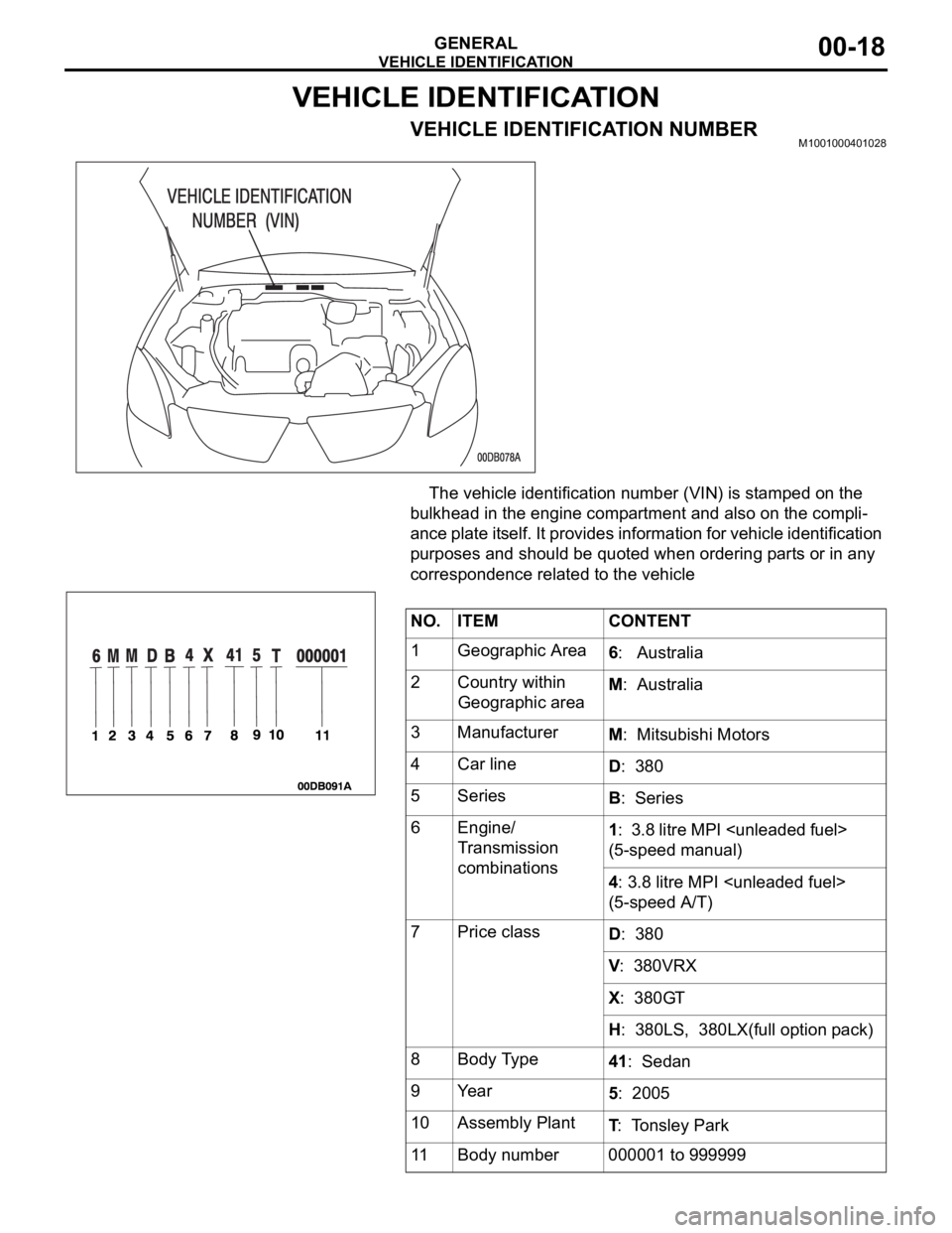
VEHICLE IDENTIFICATION NUMBERM1001000401028
The vehicle identification number (VIN) is stamped on the
bulkhead in the engine compartment and also on the compli-
ance plate itself. It provides information for vehicle identification
purposes and should be quoted when ordering parts or in any
correspondence related to the vehicle
NO. ITEM CONTENT
1 Geographic Area
6: Australia
2 Country within
Geographic areaM: Australia
3 Manufacturer
M: Mitsubishi Motors
4 Car line
D: 380
5Series
B: Series
6 Engine/
Transmission
combinations1: 3.8 litre MPI
(5-speed manual)
4: 3.8 litre MPI
(5-speed A/T)
7Price class
D: 380
V: 380VRX
X: 380GT
H: 380LS, 380LX(full option pack)
8 Body Type
41: Sedan
9Year
5: 2005
10 Assembly Plant
T: Tonsley Park
11 Body number 000001 to 999999
Page 1240 of 1500
VEHICLE IDENTIFICATION
GENERAL00-19
VEHICLE INFORMATION NUMBER LIST
NOTE: ** = Becomes 380LX as a full option pack.
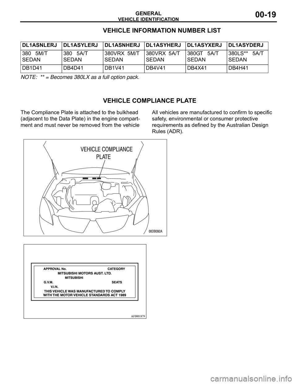
VEHICLE COMPLIANCE PLATE
The Compliance Plate is attached to the bulkhead
(adjacent to the Data Plate) in the engine compart-
ment and must never be removed from the vehicle All vehicles are manufactured to confirm to specific
safety, environmental or consumer protective
requirements as defined by the Australian Design
Rules (ADR). DL1ASNLERJ DL1ASYLERJ DL1ASNHERJ DL1ASYHERJ DL1ASYXERJ DL1ASYDERJ
380 5M/T
SEDAN380 5A/T
SEDAN380VRX 5M/T
SEDAN380VRX 5A/T
SEDAN380GT 5A/T
SEDAN380LS** 5A/T
SEDAN
DB1D41 DB4D41 DB1V41 DB4V41 DB4X41 DB4H41
Page 1241 of 1500
VEHICLE IDENTIFICATION
GENERAL00-20
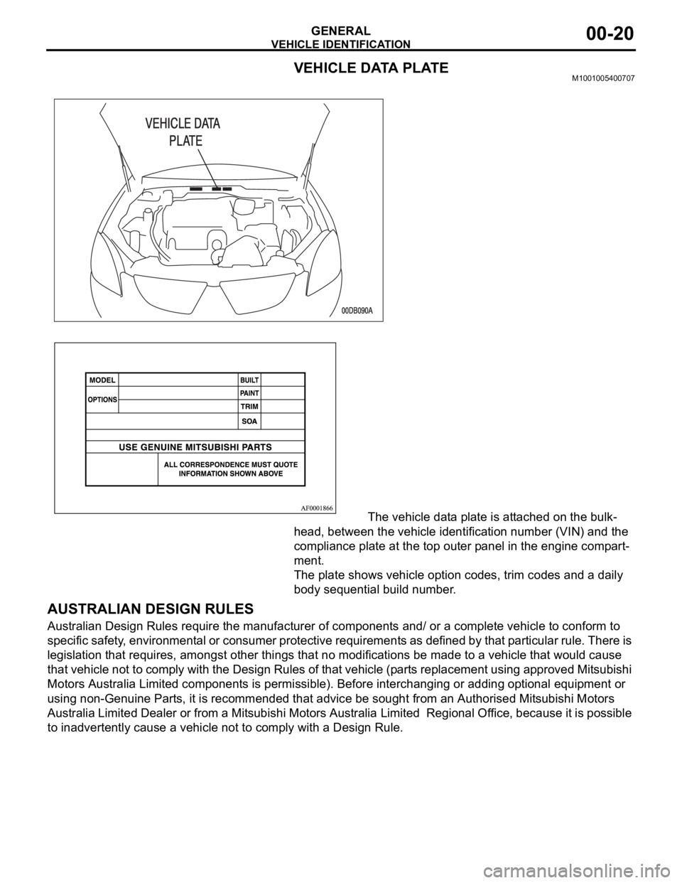
VEHICLE DATA PLATEM1001005400707
The vehicle data plate is attached on the bulk-
head, between the vehicle identification number (VIN) and the
compliance plate at the top outer panel in the engine compart-
ment.
The plate shows vehicle option codes, trim codes and a daily
body sequential build number.
AUSTRALIAN DESIGN RULES
Australian Design Rules require the manufacturer of components and/ or a complete vehicle to conform to
specific safety, environmental or consumer protective requirements as defined by that particular rule. There is
legislation that requires, amongst other things that no modifications be made to a vehicle that would cause
that vehicle not to comply with the Design Rules of that vehicle (parts replacement using approved Mitsubishi
Motors Australia Limited components is permissible). Before interchanging or adding optional equipment or
using non-Genuine Parts, it is recommended that advice be sought from an Authorised Mitsubishi Motors
Australia Limited Dealer or from a Mitsubishi Motors Australia Limited Regional Office, because it is possible
to inadvertently cause a vehicle not to comply with a Design Rule.
Page 1243 of 1500
PRECAUTIONS BEFORE SERVICE
GENERAL00-22
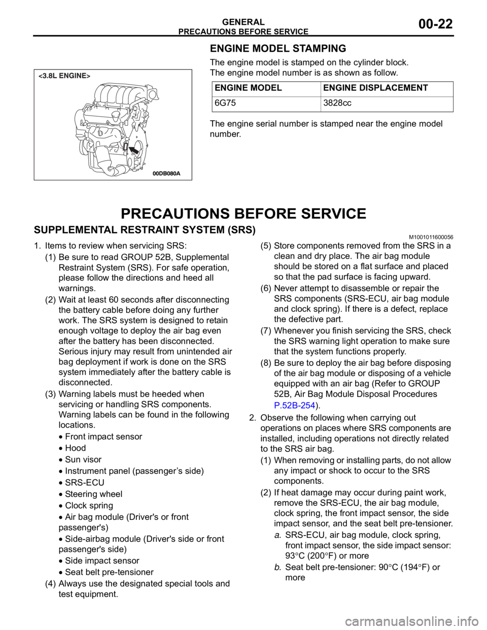
ENGINE MODEL STAMPING
The engine model is stamped on the cylinder block.
The engine model number is as shown as follow.
The engine serial number is stamped near the engine model
number.
PRECAUTIONS BEFORE SERVICE
SUPPLEMENTAL RESTRAINT SYSTEM (SRS)M1001011600056
1. Items to review when servicing SRS:
(1) Be sure to read GROUP 52B, Supplemental
Restraint System (SRS). For safe operation,
please follow the directions and heed all
warnings.
(2) Wait at least 60 seconds after disconnecting
the battery cable before doing any further
work. The SRS system is designed to retain
enough voltage to deploy the air bag even
after the battery has been disconnected.
Serious injury may result from unintended air
bag deployment if work is done on the SRS
system immediately after the battery cable is
disconnected.
(3) Warning labels must be heeded when
servicing or handling SRS components.
Warning labels can be found in the following
locations.
Front impact sensor
Hood
Sun visor
Instrument panel (passenger ’s side)
SRS-ECU
Steering wheel
Clock spring
Air bag module (Driver's or front
passenger's)
Side-airbag module (Driver's side or front
passenger's side)
Side impact sensor
Seat belt pre-tensioner
(4) Always use the designated special tools and
test equipment.(5) Store components removed from the SRS in a
clean and dry place. The air bag module
should be stored on a flat surface and placed
so that the pad surface is facing upward.
(6) Never attempt to disassemble or repair the
SRS components (SRS-ECU, air bag module
and clock spring). If there is a defect, replace
the defective part.
(7) Whenever you finish servicing the SRS, check
the SRS warning light operation to make sure
that the system functions properly.
(8) Be sure to deploy the air bag before disposing
of the air bag module or disposing of a vehicle
equipped with an air bag (Refer to GROUP
52B, Air Bag Module Disposal Procedures
P.52B-254).
2. Observe the following when carrying out
operations on places where SRS components are
installed, including operations not directly related
to the SRS air bag.
(1) When removing or installing parts, do not allow
any impact or shock to occur to the SRS
components.
(2) If heat damage may occur during paint work,
remove the SRS-ECU, the air bag module,
clock spring, the front impact sensor, the side
impact sensor, and the seat belt pre-tensioner.
a.SRS-ECU, air bag module, clock spring,
front impact sensor, the side impact sensor:
93
C (200F) or more
b.Seat belt pre-tensioner: 90
C (194F) or
more ENGINE MODEL ENGINE DISPLACEMENT
6G75 3828cc
Page 1244 of 1500
PRECAUTIONS BEFORE SERVICE
GENERAL00-23
HOW TO PERFORM VEHICLE IDENTIFICATION
NUMBER (VIN) WRITING
M1001011400063
The Vehicle Identification Number (VIN) is stored in the ECU by
the vehicle manufacture. If the VIN to be stored in the ECU is
eliminated fraudulently, the Malfunction Indicator Lamp (Check
Engine Lamp) illuminates and Diagnostic Trouble Code (DTC)
No.P0630 (VIN malfunction) is shown. When the ECU is
replaced, and entry of the VIN necessary due to DTC No.
P0630 (VIN malfunction). Enter the VIN in accordance with the
procedure as follows:
.
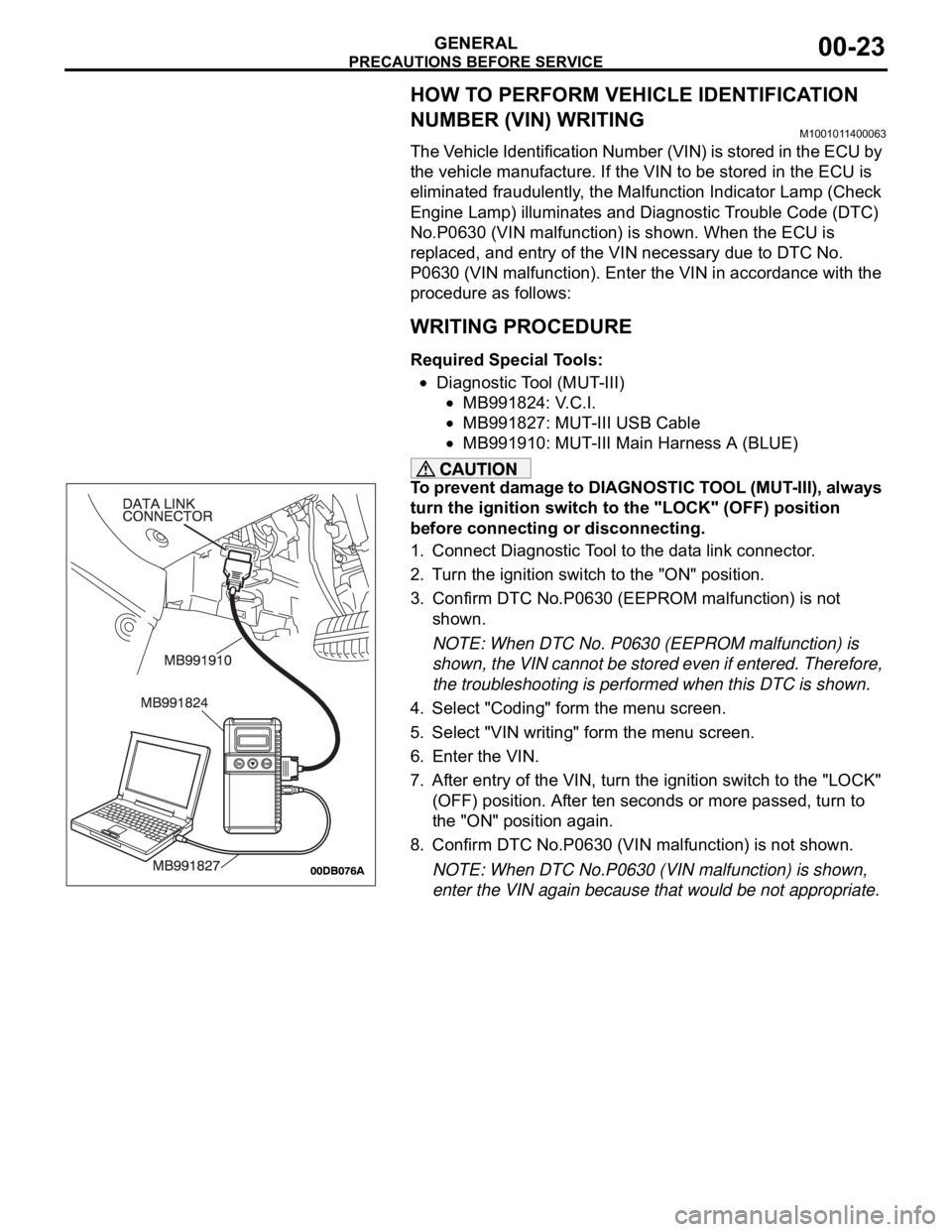
WRITING PROCEDURE
Required Special Tools:
Diagnostic Tool (MUT-III)
MB991824: V.C.I.
MB991827: MUT-III USB Cable
MB991910: MUT-III Main Harness A (BLUE)
To prevent damage to DIAGNOSTIC TOOL (MUT-III), always
turn the ignition switch to the "LOCK" (OFF) position
before connecting or disconnecting.
1. Connect Diagnostic Tool to the data link connector.
2. Turn the ignition switch to the "ON" position.
3. Confirm DTC No.P0630 (EEPROM malfunction) is not
shown.
NOTE: When DTC No. P0630 (EEPROM malfunction) is
shown, the VIN cannot be stored even if entered. Therefore,
the troubleshooting is performed when this DTC is shown.
4. Select "Coding" form the menu screen.
5. Select "VIN writing" form the menu screen.
6. Enter the VIN.
7. After entry of the VIN, turn the ignition switch to the "LOCK"
(OFF) position. After ten seconds or more passed, turn to
the "ON" position again.
8. Confirm DTC No.P0630 (VIN malfunction) is not shown.
NOTE: When DTC No.P0630 (VIN malfunction) is shown,
enter the VIN again because that would be not appropriate.
Page 1245 of 1500
PRECAUTIONS BEFORE SERVICE
GENERAL00-24
SERVICING ELECTRICAL SYSTEMM1001011900057
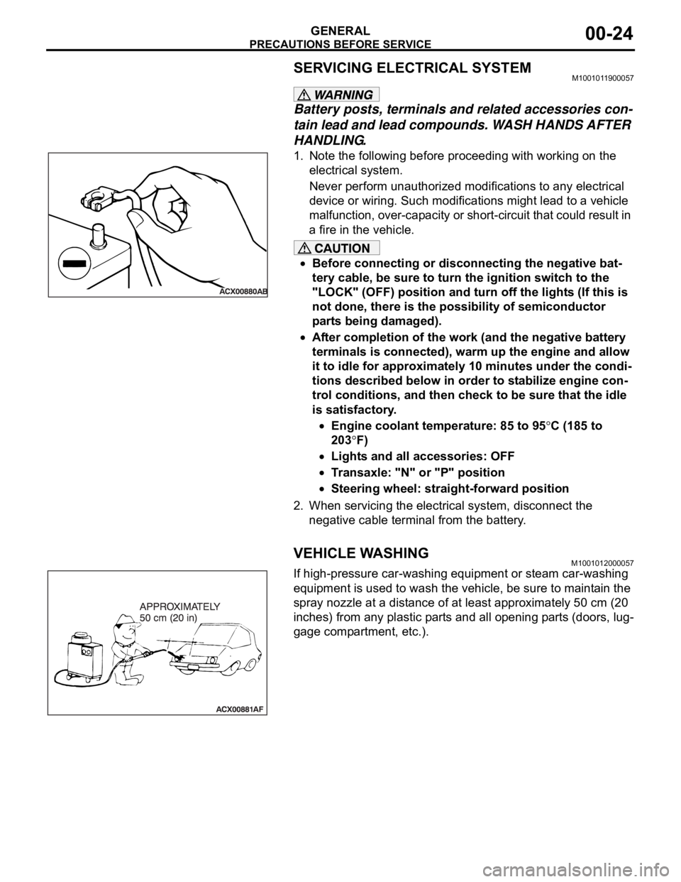
Battery posts, terminals and related accessories con-
tain lead and lead compounds. WASH HANDS AFTER
HANDLING.
1. Note the following before proceeding with working on the
electrical system.
Never perform unauthorized modifications to any electrical
device or wiring. Such modifications might lead to a vehicle
malfunction, over-capacity or short-circuit that could result in
a fire in the vehicle.
Before connecting or disconnecting the negative bat-
tery cable, be sure to turn the ignition switch to the
"LOCK" (OFF) position and turn off the lights (If this is
not done, there is the possibility of semiconductor
parts being damaged).
After completion of the work (and the negative battery
terminals is connected), warm up the engine and allow
it to idle for approximately 10 minutes under the condi-
tions described below in order to stabilize engine con-
trol conditions, and then check to be sure that the idle
is satisfactory.
Engine coolant temperature: 85 to 95C (185 to
203
F)
Lights and all accessories: OFF
Transaxle: "N" or "P" position
Steering wheel: straight-forward position
2. When servicing the electrical system, disconnect the
negative cable terminal from the battery.
VEHICLE WASHINGM1001012000057
If high-pressure car-washing equipment or steam car-washing
equipment is used to wash the vehicle, be sure to maintain the
spray nozzle at a distance of at least approximately 50 cm (20
inches) from any plastic parts and all opening parts (doors, lug-
gage compartment, etc.).