Page 998 of 1500

STARTING SYSTEM
ENGINE ELECTRICAL16-21
STARTING SYSTEM DIAGNOSISM1162000700293
TROUBLESHOOTING HINTS
The starter motor does not operate at all.
Battery posts, terminals and related accessories con-
tain lead and lead compounds. WASH HANDS AFTER
HANDLING.
Check the starter (coil).
Check for poor contact at the battery terminals and
starter.
Check the transmission range switch.
The starter motor doesn't stop
Check the starter (magnetic switch).
TROUBLESHOOTING GUIDE
The starting system troubleshooting guide is shown in the fol-
lowing steps.
Battery posts, terminals and related accessories con-
tain lead and lead compounds. WASH HANDS AFTER
HANDLING.
STEP 1.
Q: Is the battery in good condition? (Refer to GROUP 54A,
Chassis Electrical
Battery On-vehicle Service
Battery Check P.54A-5.)
YES : Go to Step 2.
NO : Charge or replace the battery.
STEP 2.
Disconnect the starter motor S (solenoid) terminal connec-
tor.
Using a jumper wire, apply battery positive voltage to the
starter motor S (solenoid) terminal.
Check the engine condition.
OK: Turns normally
Q: Dose the starter motor operate normally?
YES :
Check the ignition switch (Refer to GROUP 54A,
Chassis Electrical
Ignition Switch Ignition
Switch
Inspection P.54A-44.)
Check the transmission range switch. (Refer to
GROUP 23A, Automatic Transaxle
On-vehicle
Service
Essential Service Transmission Range
Switch Check P.23A-294.)
Check the wire between the battery and starter
motor S (solenoid) terminal.
NO : Go to Step 3.
Page 999 of 1500
STARTING SYSTEM
ENGINE ELECTRICAL16-22
STEP 3.
Check the cable between starter B (battery) terminal and
battery positive terminal for connection and continuity.
Q: Is the starter cable in good condition?
YES : Go to Step 4.
NO : Repair or replace the cable.
STEP 4.
Check the connection and the continuity of the cable
between the starter motor body and the negative battery
terminal.
Q: Is the ground wire in good condition?
YES : Go to Step 5.
NO : Repair or replace the cable.
STEP 5.
Q: Is the starter motor in good condition? (Refer to Starting
System
Starter Motor Assembly Inspection P.16-17.)
YES : Excessive rotational resistance of the engine.
NO : Replace the starter motor.
Page 1000 of 1500
STARTING SYSTEM
ENGINE ELECTRICAL16-23
STARTER MOTOR ASSEMBLY
REMOVAL AND INSTALLATION M1162001000651
Pre-removal and Post-installation Operation
Under Cover Removal and Installation (Refer to GROUP 51,
Under Cover P.51-13).
REMOVAL STEPS
1. STARTER CONNECTOR AND
TERMINAL2. STARTER COVER
<>3. STARTER ASSEMBLYREMOVAL STEPS (Continued)
Page 1001 of 1500
Page 1002 of 1500

STARTING SYSTEM
ENGINE ELECTRICAL16-25
.
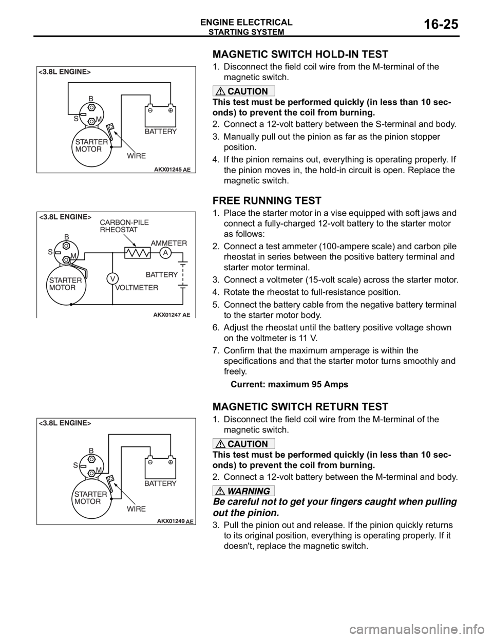
MAGNETIC SWITCH HOLD-IN TEST
1. Disconnect the field coil wire from the M-terminal of the
magnetic switch.
This test must be performed quickly (in less than 10 sec-
onds) to prevent the coil from burning.
2. Connect a 12-volt battery between the S-terminal and body.
3. Manually pull out the pinion as far as the pinion stopper
position.
4. If the pinion remains out, everything is operating properly. If
the pinion moves in, the hold-in circuit is open. Replace the
magnetic switch.
.
FREE RUNNING TEST
1. Place the starter motor in a vise equipped with soft jaws and
connect a fully-charged 12-volt battery to the starter motor
as follows:
2. Connect a test ammeter (100-ampere scale) and carbon pile
rheostat in series between the positive battery terminal and
starter motor terminal.
3. Connect a voltmeter (15-volt scale) across the starter motor.
4. Rotate the rheostat to full-resistance position.
5. Connect the battery cable from the negative battery terminal
to the starter motor body.
6. Adjust the rheostat until the battery positive voltage shown
on the voltmeter is 11 V.
7. Confirm that the maximum amperage is within the
specifications and that the starter motor turns smoothly and
freely.
Current: maximum 95 Amps
.
MAGNETIC SWITCH RETURN TEST
1. Disconnect the field coil wire from the M-terminal of the
magnetic switch.
This test must be performed quickly (in less than 10 sec-
onds) to prevent the coil from burning.
2. Connect a 12-volt battery between the M-terminal and body.
Be careful not to get your fingers caught when pulling
out the pinion.
3. Pull the pinion out and release. If the pinion quickly returns
to its original position, everything is operating properly. If it
doesn't, replace the magnetic switch.
Page 1003 of 1500
Page 1004 of 1500
Page 1005 of 1500
STARTING SYSTEM
ENGINE ELECTRICAL16-28
INSPECTIONM1162001300102.
COMMUTATOR CHECK
1. Place the armature on a pair of V-blocks, and check the
deflection by using a dial gauge.
Standard value: 0.05 mm (0.002 inch)
Limit: 0.1 mm (0.004 inch)
2. Check the outer diameter of the commutator.
Standard value: 29.4 mm (1.16 inches)
Minimum limit: 28.8 mm (1.13 inches)
3. Check the depth of the undercut between segments.
Standard value: 0.5 mm (0.02 inch)
Minimum limit: 0.2 mm (0.008 inch)
.
BRUSH CHECK
1. Check the brush for roughness of the surface that contacts
the commutator and check the brush length. Replace the
brush holder if this measurement exceeds the limit.
Minimum limit:
7.0 mm (0.28 inch)
2. If the contacting surface has been corrected or the brush
has been replaced, correct the contacting surface by
winding sandpaper around the commutator.
.