2005 MERCEDES-BENZ SPRINTER wheel
[x] Cancel search: wheelPage 94 of 1232
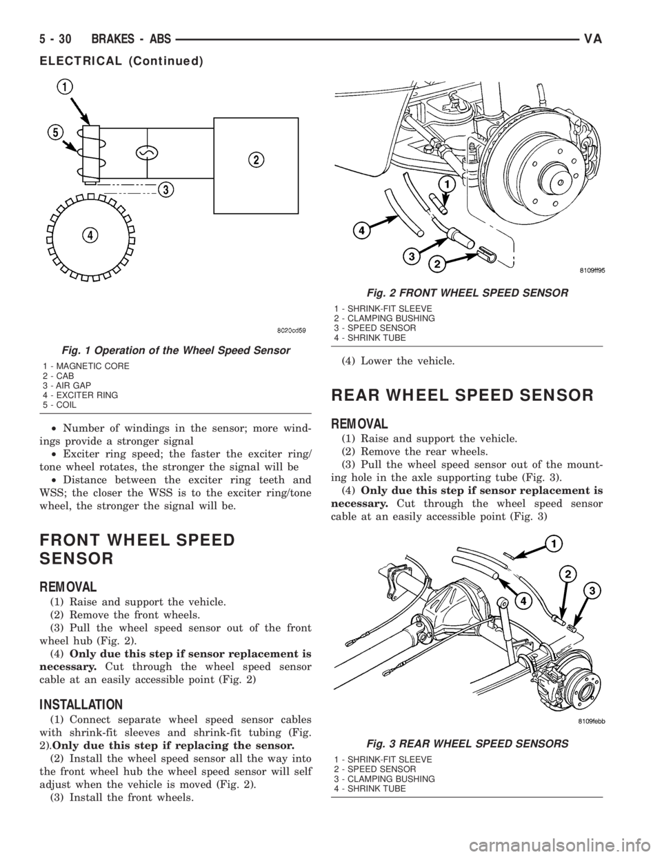
²Number of windings in the sensor; more wind-
ings provide a stronger signal
²Exciter ring speed; the faster the exciter ring/
tone wheel rotates, the stronger the signal will be
²Distance between the exciter ring teeth and
WSS; the closer the WSS is to the exciter ring/tone
wheel, the stronger the signal will be.
FRONT WHEEL SPEED
SENSOR
REMOVAL
(1) Raise and support the vehicle.
(2) Remove the front wheels.
(3) Pull the wheel speed sensor out of the front
wheel hub (Fig. 2).
(4)Only due this step if sensor replacement is
necessary.Cut through the wheel speed sensor
cable at an easily accessible point (Fig. 2)
INSTALLATION
(1) Connect separate wheel speed sensor cables
with shrink-fit sleeves and shrink-fit tubing (Fig.
2).Only due this step if replacing the sensor.
(2) Install the wheel speed sensor all the way into
the front wheel hub the wheel speed sensor will self
adjust when the vehicle is moved (Fig. 2).
(3) Install the front wheels.(4) Lower the vehicle.
REAR WHEEL SPEED SENSOR
REMOVAL
(1) Raise and support the vehicle.
(2) Remove the rear wheels.
(3) Pull the wheel speed sensor out of the mount-
ing hole in the axle supporting tube (Fig. 3).
(4)Only due this step if sensor replacement is
necessary.Cut through the wheel speed sensor
cable at an easily accessible point (Fig. 3)
Fig. 1 Operation of the Wheel Speed Sensor
1 - MAGNETIC CORE
2 - CAB
3 - AIR GAP
4 - EXCITER RING
5 - COIL
Fig. 2 FRONT WHEEL SPEED SENSOR
1 - SHRINK-FIT SLEEVE
2 - CLAMPING BUSHING
3 - SPEED SENSOR
4 - SHRINK TUBE
Fig. 3 REAR WHEEL SPEED SENSORS
1 - SHRINK-FIT SLEEVE
2 - SPEED SENSOR
3 - CLAMPING BUSHING
4 - SHRINK TUBE
5 - 30 BRAKES - ABSVA
ELECTRICAL (Continued)
Page 95 of 1232
INSTALLATION
(1) Connect separate wheel speed sensor cables
with shrink-fit sleeves and shrink-fit tubing (Fig.
3).Only due this step if replacing the sensor.
(2) Install the wheel speed sensor all the way into
the axle tube, the wheel speed sensor will self adjust
when the vehicle is moved (Fig. 3).
(3) Install the rear wheels.
(4) Lower the vehicle.
TONE WHEEL
REMOVAL
(1) Remove the hub/bearing assembly (DRW)
(Refer to 3 - DIFFERENTIAL & DRIVELINE/REAR
AXLE/AXLE BEARINGS - REMOVAL).
(2) Insert a hooked prybar between the hub/bear-
ing and the inside of the tone wheel and pry upwards
slightly and work your way around the tone wheel
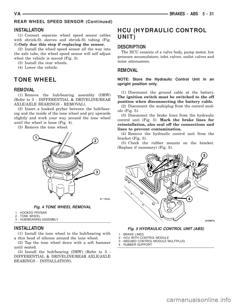
until the wheel is loose (Fig. 4).
(3) Remove the tone wheel.
INSTALLATION
(1) Install the tone wheel to the hub/bearing with
a thin bead of silicone around the tone wheel.
(2) Tap the tone wheel down with a soft hammer
until seated.
(3) Install the hub/bearing (DRW) (Refer to 3 -
DIFFERENTIAL & DRIVELINE/REAR AXLE/AXLE
BEARINGS - INSTALLATION).
HCU (HYDRAULIC CONTROL
UNIT)
DESCRIPTION
The HCU consists of a valve body, pump motor, low
pressure accumulators, inlet valves, outlet valves and
noise attenuators.
REMOVAL
NOTE: Store the Hydraulic Control Unit in an
upright position only.
(1) Disconnect the ground cable at the battery.
The ignition switch must be switched to the off
position when disconnecting the battery cable.
(2) Disconnect the multiplug from the control mod-
ule (Fig. 5).
(3) Disconnect the brake lines from the hydraulic
control unit (Fig. 5).Mark the brake lines for
reinstallation, also seal off the connections and
lines to prevent contamination.
(4) Remove the hydraulic control unit from the
bracket (Fig. 5).
(5) Check the rubber mounts on the bracket.
(Replace if necessary) (Fig. 5).
Fig. 4 TONE WHEEL REMOVAL
1 - HOOKED PRYBAR
2 - TONE WHEEL
3 - HUB/BEARING ASSEMBLY
Fig. 5 HYDRAULIC CONTROL UNIT (ABS)
1 - BRAKE LINES
2 - HCU WITH CONTROL MODULE
3 - ABS/ABD CONTROL MODULE MULTIPLUG
4 - RUBBER SUPPORT
VABRAKES - ABS 5 - 31
REAR WHEEL SPEED SENSOR (Continued)
Page 120 of 1232
²Lights-On Warning- The EMIC chime tone
generator will generate repetitive chime tones at a
fast rate when either front door is opened with the
ignition switch in any position except On, and the
exterior lights are turned On. The EMIC uses inter-
nal programming and hard wired inputs from the left
(lighting) control stalk of the multi-function switch,
the ignition switch, and both front door jamb
switches to determine the current status of these
switches. This chime will continue to sound until the
exterior lighting is turned Off, until the ignition
switch is turned to the On position, or until both
front doors are closed, whichever occurs first.
²Key-In-Ignition Warning-
The EMIC chime
tone generator will generate repetitive chime tones at a
fast rate when the key is in the ignition lock cylinder,
the ignition switch is in any position except On, and
either front door is opened. The EMIC uses internal
programming and hard wired inputs from the key-in
ignition switch, the ignition switch, and both front door
jamb switches to determine the current status of these
switches. The chime will continue to sound until the key
is removed from the ignition lock cylinder, until the
ignition switch is turned to the On position, or until
both front doors are closed, whichever occurs first.
²Audible Turn Signal/Hazard Warning Sup-
port-
The EMIC contactless relay will generate repeti-
tive clicks at a slow rate during normal turn signal/
hazard warning operation, or at a fast rate when a turn
signal lamp bulb or circuit is inoperative, in concert with
the operation of the turn signal indicators in the cluster.
These clicks are designed to emulate the sound of the
opening and closing of the contact points in a conven-
tional electro-mechanical turn signal or hazard warning
flasher. The EMIC uses a hard wired input received from
the turn signal relay in the fuse block beneath the steer-
ing column through the turn signal or hazard warning
switch circuitry of the multi-function switch to determine
when to flash the turn signal indicators and activate the
contactless relay on the cluster electronic circuit board.
The turn signal clicks will continue to sound until the
turn signal switch is turned Off, or until the ignition
switch is turned to the Off position, whichever occurs
first. The hazard warning clicks will continue to sound
until the hazard warning switch is turned Off.
The EMIC provides chime service for all available
features in the chime warning system. The EMIC relies
upon its internal programming and hard wired inputs
from the front door ajar switches, the key-in ignition
switch, the ignition switch, the seat belt switch, and the
turn signal/hazard warning (multi-function) switches.
The EMIC relies upon electronic message inputs
received from other electronic modules over the CAN
data bus network to provide chime service for the low
engine oil level warning. Upon receiving the proper
inputs, the EMIC activates the chime tone generator orthe contactless relay to provide the audible warning to
the vehicle operator. The internal programming of the
EMIC determines the priority of each chime request
input that is received, as well as the rate and duration
of each tone that is to be generated. See the owner's
manual in the vehicle glove box for more information on
the features provided by the chime warning system.
The hard wired chime warning system inputs to
the EMIC, as well as other hard wired circuits for
this system may be diagnosed and tested using con-
ventional diagnostic tools and procedures. However,
conventional diagnostic methods may not prove con-
clusive in the diagnosis of the EMIC, the CAN data
bus network, or the electronic message inputs used
by the EMIC to provide chime warning system ser-
vice. The most reliable, efficient, and accurate means
to diagnose the EMIC, the CAN data bus network,
and the electronic message inputs for the chime
warning system requires the use of a DRBIIItscan
tool. Refer to the appropriate diagnostic information.
DIAGNOSIS AND TESTING - CHIME WARNING
SYSTEM
WARNING: ON VEHICLES EQUIPPED WITH AIRBAGS,
DISABLE THE SUPPLEMENTAL RESTRAINT SYSTEM
BEFORE ATTEMPTING ANY STEERING WHEEL,
STEERING COLUMN, DRIVER AIRBAG, PASSENGER
AIRBAG, SEAT BELT TENSIONER, OR INSTRUMENT
PANEL COMPONENT DIAGNOSIS OR SERVICE. DIS-
CONNECT AND ISOLATE THE BATTERY NEGATIVE
(GROUND) CABLE, THEN WAIT TWO MINUTES FOR
THE SYSTEM CAPACITOR TO DISCHARGE BEFORE
PERFORMING FURTHER DIAGNOSIS OR SERVICE.
THIS IS THE ONLY SURE WAY TO DISABLE THE SUP-
PLEMENTAL RESTRAINT SYSTEM. FAILURE TO TAKE
THE PROPER PRECAUTIONS COULD RESULT IN
ACCIDENTAL AIRBAG DEPLOYMENT AND POSSIBLE
PERSONAL INJURY.
The hard wired chime warning system inputs to
the Electro-Mechanical Instrument Cluster (EMIC),
as well as other hard wired circuits for this system
may be diagnosed and tested using conventional
diagnostic tools and procedures. However, conven-
tional diagnostic methods may not prove conclusive
in the diagnosis of the EMIC, the Controller Area
Network (CAN) data bus network, or the electronic
message inputs used by the EMIC to provide chime
warning system service. The most reliable, efficient,
and accurate means to diagnose the EMIC, the CAN
data bus network, and the electronic message inputs
for the chime warning system requires the use of a
DRBIIItscan tool. Refer to the appropriate diagnos-
tic information.
8B - 2 CHIME/BUZZERVA
CHIME/BUZZER (Continued)
Page 122 of 1232
OPERATION
The central timer module (CTM) monitors many
hard wired switch and sensor inputs as well as those
resources it shares with other modules in the vehicle
through its communication over the programmable
communications interface (PCI) data bus network.
The internal programming and all of these inputs
allow the CTM to determine the tasks it needs to
perform and their priorities, as well as both the stan-
dard and optional features that it should provide.
The CTM then performs those tasks and provides
those features through both PCI data bus communi-
cation with other modules and hard wired outputs
through a number of driver circuits, relays, and
actuators.These outputs allow the CTM the ability to
control numerous accessory systems in the vehicle.
The CTM monitors its own internal circuitry as
well as many of its input and output circuits, and
will store a Diagnostic Trouble Code (DTC) in elec-
tronic memory for any failure it detects. These DTCs
can be retrieved and diagnosed using a DRBIIItscan
tool. Refer to the appropriate diagnostic information.
HARD WIRED INPUTS
The hard wired inputs to the CTM include the fol-
lowing:
²Fused B(+)
²Fused ignition switch output (run-acc)
²Fused ignition switch output (run-start)
²Ground
²Key-in ignition switch sense
²Sliding door switch sense
²Passenger door switch sense
²Driver door switch sense
²PCI bus circuit
HARD WIRED OUTPUTS
The hard wired outputs of the CTM include the fol-
lowing:
²Door lock relay output
²Door unlock relay output
²VTSS indicator driver
MESSAGING
The CTM uses the following messages received
from other electronic modules over the PCI data bus:
²Airbag Deploy (ACM)
²Beep request (CMTC)
²Charging System Failure (PCM)
²Chime request (EMIC)
²Engine RPM (PCM)
²OK to Arm VTSS (PCM)
²Security indicator request (SKIM)
²System Voltage (PCM)
²Valid/Invalid Key (SKIM)
²Vehicle Distance (PCM)²Vehicle Speed (PCM)DIAGNOSIS AND TESTING - CENTRAL TIMER
MODULE
WARNING: ON VEHICLES EQUIPPED WITH AIR-
BAGS, DISABLE THE AIRBAG SYSTEM BEFORE
ATTEMPTING ANY STEERING WHEEL, STEERING
COLUMN, SEAT BELT TENSIONER, OR INSTRU-
MENT PANEL COMPONENT DIAGNOSIS OR SER-
VICE. DISCONNECT AND ISOLATE THE BATTERY
NEGATIVE (GROUND) CABLE, THEN WAIT TWO
MINUTES FOR THE AIRBAG SYSTEM CAPACITOR
TO DISCHARGE BEFORE PERFORMING FURTHER
DIAGNOSIS OR SERVICE. THIS IS THE ONLY SURE
WAY TO DISABLE THE AIRBAG SYSTEM. FAILURE
TO TAKE THE PROPER PRECAUTIONS COULD
RESULT IN ACCIDENTAL AIRBAG DEPLOYMENT
AND POSSIBLE PERSONAL INJURY.
The hard wired inputs to and outputs from the
central timer module (CTM) may be diagnosed and
tested using conventional diagnostic tools and meth-
ods. Refer to the appropriate wiring information.
However, conventional diagnostic methods may not
prove conclusive in the diagnosis of the CTM. In
order to obtain conclusive testing of the CTM, the
programmable communications interface (PCI) data
bus network and all of the modules that provide
inputs to or receive outputs from the CTM must also
be checked. The most reliable, efficient, and accurate
means to diagnose the CTM, the PCI data bus net-
work, and the modules that provide inputs to, or
receive outputs from, the CTM requires the use of a
DRBIIItscan tool. Refer to the appropriate diagnos-
tic information.
REMOVAL
(1) Disconnect and isolate the battery negative
cable.
(2) Slide the driver seat to the full forward posi-
tion.
(3) Disconnect the wire harness connector for the
seat belt latch. (Fig. 1).
(4) Remove the screws that secure the closeout
panel beneathe the driver seat cushion and remove
the panel.
(5) Remove the screws that secure the central
timer module to the bracket.
(6) Disconnect the wire harness connectors from
the central timer module.
(7) Remove the central timer module from the
vehicle.
INSTALLATION
(1) Position the central timer module in the vehicle
8E - 2 ELECTRONIC CONTROL MODULESVA
CENTRAL TIMER MODULE (Continued)
Page 125 of 1232
TRANSMISSION CONTROL
MODULE
DESCRIPTION
The transmission control module (TCM) receives,
processes and sends various digital and analog sig-
nals related to the automatic transmission. In addi-
tion, it processes information received from other
vehicle systems, such as engine torque and speed,
accelerator pedal position, wheel speed, kick-down
switch, traction control information, etc.
The TCM is located under the driver's seat and is
connected to other control modules via a CAN bus. It
controls all shift functions to achieve smooth shift
comfort in all driving situations considering:
²Vehicle speed.
²Transmission status.
²Position of selector lever.
²Selected shift range.
²CAN signals.
²Engine Status.Engine speed limits may be reached in all gears
with full throttle or in kick-down operation. In for-
ward driving, the shift range of the forward gears
can be adjusted by the operator by tipping the selec-
tor lever to the left or right (AutoStick). However, the
TCM features a downshift inhibitor to prevent the
engine from overspeeding.
OPERATION
The transmission control module (TCM) deter-
mines the current operating conditions of the vehicle
and controls the shifting process for shift comfort and
driving situations. It receives this operating data
from sensors and broadcast messages from other
modules.
The TCM uses inputs from several sensors that are
directly hardwired to the controller and it uses sev-
eral indirect inputs that are used to control shifts.
This information is used to actuate the proper sole-
noids in the valve body to achieve the desired gear.
The shift lever assembly (SLA) has several items
that are monitored by the TCM to calculate shift
lever position. The reverse light switch, an integral
part of the SLA, controls the reverse light relay con-
trol circuit. The Brake/Transmission Shift Interlock
(BTSI) solenoid and the park lockout solenoid (also
part of the SLA) are controlled by the TCM.
The ECM and ABS broadcast messages over the
controller area network (CAN C) bus for use by the
TCM. The TCM uses this information, with other
inputs, to determine the transmission operating con-
ditions.
The TCM:
²determines the momentary operating conditions
of the vehicle.
²controls all shift processes.
²considers shift comfort and the driving situation.
The TCM controls the solenoid valves for modulat-
ing shift pressures and gear changes. Relative to the
torque being transmitted, the required pressures are
calculated from load conditions, engine rpm, vehicle
speed, and ATF temperature.
The following functions are contained in the TCM:
²Shift Program
²Downshift Safety
²Torque Converter Lock-Up Clutch.
²Adaptation.
This transmission does not have a TCM relay.
Power is supplied to the SLA and the TCM directly
from the ignition.
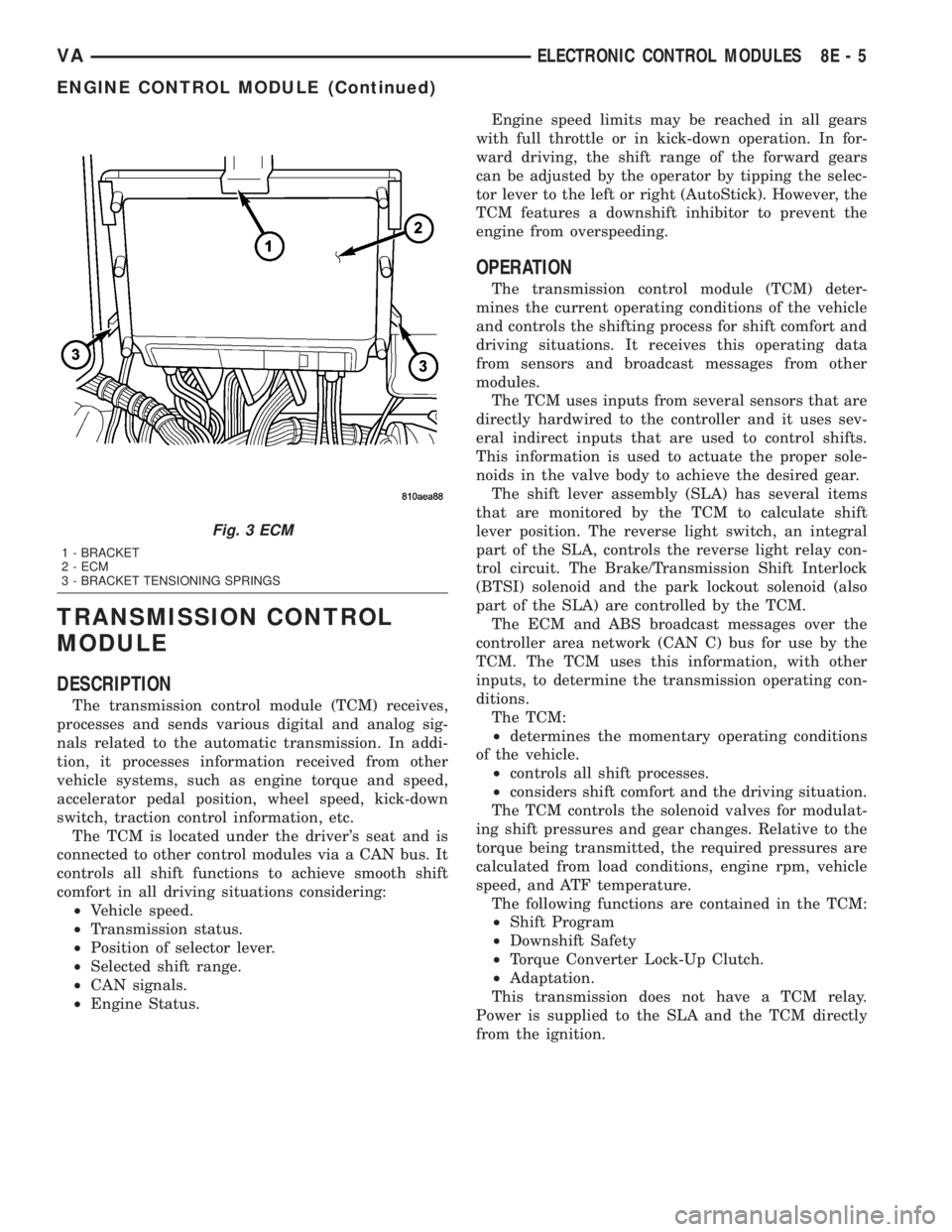
Fig. 3 ECM
1 - BRACKET
2 - ECM
3 - BRACKET TENSIONING SPRINGS
VAELECTRONIC CONTROL MODULES 8E - 5
ENGINE CONTROL MODULE (Continued)
Page 126 of 1232
The TCM continuously checks for electrical prob-
lems, mechanical problems, and some hydraulic prob-
lems. When a problem is sensed, the TCM stores a
diagnostic trouble code (DTC). Some of these codes
cause the transmission to go into9Limp-In9or
9default9mode. Some DTCs cause permanent
Limp-In and others cause temporary Limp-In. The
NAG1 defaults in the current gear position if a DTC
is detected, then after a key cycle the transmission
will go into Limp-in, which is mechanical 2nd gear.
Some DTCs may allow the transmission to resume
normal operation (recover) if the detected problem
goes away. A permanent Limp-In DTC will recover
when the key is cycled, but if the same DTC is
detected for three key cycles the system will not
recover and the DTC must be cleared from the TCM
with the DRBIIItscan tool.
TCM SIGNALS
The TCM registers one part of the input signals by
direct inputs, the other part by CAN C bus. In addi-
tion to the direct control of the actuators, the TCM
sends various output signals by CAN C bus to other
control modules.
Selector Lever Position
The TCM monitors the SLA for all shift lever posi-
tions via the CAN bus.
ATF Temperature Sensor
The ATF temperature sensor is a positive temper-
ature co-efficient (PTC) thermistor. It measures the
temperature of the transmission fluid and is a direct
input signal for the TCM. The temperature of the
ATF has an influence on the shifttime and resulting
shift quality. As the temperature rises, resistance
rises, and therefore, the probing voltage is decreas-
ing. Because of its registration, the shifting process
can be optimized in all temperature ranges.
The ATF temperature sensor is wired in series
with the park/neutral contact. The temperature sig-
nal is transmitted to the TCM only when the reed
contact of the park/neutral contact is closed because
the TCM only reads ATF temperature while in any
forward gear, or REVERSE. When the transmission
is in PARK or NEUTRAL, the TCM will substitute
the engine temperature for the ATF temperature.
Starter Interlock
The TCM monitors a contact switch wired in series
with the transmission temperature sensor to deter-
mine PARK and NEUTRAL positions. The contact
switch is open in PARK and NEUTRAL. The TCM
senses transmission temperature as high (switch
supply voltage), confirming switch status as open.
The TCM then broadcasts a message over CAN bus
to confirm switch status. The PCM receives thisinformation and allows operation of the starter cir-
cuit.
N2 and N3 Speed Sensors
The N2 and N3 Input Speed Sensors are two Hall-
effect speed sensors that are mounted internally in
the transmission and are used by the TCM to calcu-
late the transmission's input speed. Since the input
speed cannot be measured directly, two of the drive
elements are measured. Two input speed sensors
were required because both drive elements are not
active in all gears.
CAN C Bus Indirect Input Signals
A 2.5-volt bias (operating voltage) is present on the
CAN C bus any time the ignition switch is in the
RUN position. Both the TCM and the ABS apply this
bias. On this vehicle, the CAN C bus is used for mod-
ule data exchange only. The indirect inputs used on
the NAG1 electronic control system are:
²Wheel Speed Sensors.
²Brake Switch.
²Engine RPM.
²Engine Temperature.
²Cruise Control Status.
²Gear Limit Request.
²Throttle Position - 0% at idle, 100% at WOT. If
open, TCM assumes idle (0% throttle opening).
²Odometer Mileage
²Maximum Effective Torque.
²Engine in Limp-In Mode/Mileage Where DTC
Was Set.
BRAKE TRANSMISSION SHIFT INTERLOCK (BTSI)
The BTSI solenoid prevents shifting out of the
PARK position until the ignition key is in the RUN
position and the brake pedal is pressed. The TCM
controls the ground while the ignition switch supplies
power to the BTSI solenoid. The PCM monitors the
brake switch and broadcasts brake switch status
messages over the CAN C bus. If the park brake is
depressed and there is power (Run/Start) to SLA, the
BTSI solenoid deactivates.
SHIFT SCHEDULES
The basic shift schedule includes up and down-
shifts for all five gears. The TCM adapts the shift
program according to driving style, accelerator pedal
position and deviation of vehicle speed. Influencing
factors are:
²Road Conditions.
²Incline, Decline and Altitude.
²Trailer Operation, Loading.
²Engine Coolant Temperature.
²Cruise Control Operation.
²Sporty Driving Style.
8E - 6 ELECTRONIC CONTROL MODULESVA
TRANSMISSION CONTROL MODULE (Continued)
Page 144 of 1232
REMOVAL
(1) Turn the ignition switch to the Off position. Be
certain that all electrical accessories are turned off.
(2) Disconnect and isolate the remote battery neg-
ative cable terminal.
(3) One at a time, trace and disconnect the battery
cable retaining pushpins, fasteners and routing clips
until the cables are free from the vehicle.
(4)
Feed the battery cable assembly out of the vehicle.
INSTALLATION
(1) Position the battery cable in the vehicle.
(2) One at a time, install the battery cable retain-
ing pushpins, fasteners and routing clips until the
cable is installed exactly in the factory installed loca-
tion in the vehicle. Refer to the Wiring Diagram sec-
tion of the service manual for reference.
(3) Connect the battery negative cable terminal.
BATTERY TRAY
DESCRIPTION
The battery is mounted in a stamped steel battery
tray located in the left front corner of the engine
compartment. The battery tray is secured with bolts
to the left front wheelhouse inner steel panel. A hole
in the bottom of the battery tray is fitted with a
formed drain tube. A second hole in the bottom of the
tray is fitted with a battery temperature sensor.
OPERATION
The battery tray provides a mounting location and
support for the vehicle battery. The battery tray sup-
port supports the battery tray and provides an
anchor point for the inboard battery hold down hard-
ware. The battery tray and the battery hold down
hardware combine to secure and stabilize the battery
in the engine compartment, which prevents battery
movement during vehicle operation. Unrestrained
battery movement during vehicle operation could
result in damage to the vehicle, the battery or both.
The battery tray drain tube directs spilled water or
electrolyte from a leaking battery to the ground
through another hole in the front extension of the
left front wheelhouse inner panel.
REMOVAL
(1) Remove the battery from the battery tray.
(Refer to 8 - ELECTRICAL/BATTERY SYSTEM/BAT-
TERY - REMOVAL).
(2) Remove the battery temperature sensor from
the battery tray. (Refer to 8 - ELECTRICAL/CHARG-
ING/BATTERY TEMPERATURE SENSOR -
REMOVAL).
(3) Remove the bolts that secure the battery tray
to the battery tray support.
(4) Remove the battery tray from the vehicle.
INSTALLATION
(1) Clean and inspect the battery tray.(Refer to 8 -
ELECTRICAL/BATTERY SYSTEM - CLEANING).
(2) Position the battery tray onto the battery tray
support.
(3) Install and tighten the bolts that secure the
battery tray to the battery tray support. Tighten the
screws to 11.8 N´m (105 in. lbs.).
(4) Install the battery temperature sensor onto the
battery tray. (Refer to 8 - ELECTRICAL/CHARGING/
BATTERY TEMPERATURE SENSOR - INSTALLA-
TION).
(5) Install the battery onto the battery tray. (Refer
to 8 - ELECTRICAL/BATTERY SYSTEM/BATTERY -
INSTALLATION).
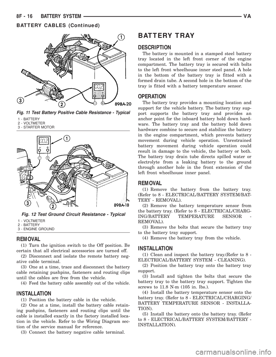
Fig. 11 Test Battery Positive Cable Resistance - Typical
1 - BATTERY
2 - VOLTMETER
3 - STARTER MOTOR
Fig. 12 Test Ground Circuit Resistance - Typical
1 - VOLTMETER
2 - BATTERY
3 - ENGINE GROUND
8F - 16 BATTERY SYSTEMVA
BATTERY CABLES (Continued)
Page 152 of 1232
STARTING SYSTEM
TABLE OF CONTENTS
page page
STARTING SYSTEM
DESCRIPTION.........................24
OPERATION...........................24
DIAGNOSIS AND TESTING - STARTING
SYSTEM............................25
SPECIFICATIONS
TORQUE - STARTER - DIESEL...........29
SPECIFICATIONS - STARTER MOTOR -
DIESEL.............................29STARTER MOTOR
DIAGNOSIS AND TESTING - STARTER
MOTOR .............................29
REMOVAL.............................30
INSTALLATION.........................31
STARTER MOTOR RELAY
DESCRIPTION.........................31
REMOVAL.............................31
INSTALLATION.........................32
STARTING SYSTEM
DESCRIPTION
The starting system consists of:
²Starter relay
²Starter motor (including an integral starter sole-
noid)
Other components to be considered as part of start-
ing system are:
²Battery
²Battery cables
²Ignition switch and key lock cylinder
²Park/neutral position switch (automatic trans-
mission)
²Wire harnesses and connections.
The Battery, Starting, and Charging systems oper-
ate in conjunction with one another, and must be
tested as a complete system. For correct operation of
starting/charging systems, all components used in
these 3 systems must perform within specifications.
When attempting to diagnose any of these systems, it
is important that you keep their interdependency in
mind.
The diagnostic procedures used in each of these
groups include the most basic conventional diagnostic
methods, to the more sophisticated On-Board Diag-
nostics (OBD) built into the Engine Control Module
(ECM). Use of an induction-type milliampere amme-
ter, volt/ohmmeter, battery charger, carbon pile rheo-
stat (load tester), and 12-volt test lamp may be
required.
Certain starting system components are monitored
by the ECM and may produce a Diagnostic Trouble
Code (DTC).
OPERATION
The starting system components form two separate
circuits. A high-amperage feed circuit that feeds thestarter motor high-amperage, and a low-amperage
control circuit that operates on less than 20 amperes.
The high-amperage feed circuit components include
the battery, the battery cables, the contact disc por-
tion of the starter solenoid, and the starter motor
itself. The low-amperage control circuit components
include the ignition switch, the park/neutral position
switch (automatic transmission), the starter relay,
the electromagnetic windings of the starter solenoid,
and the connecting wire harness components.
If the vehicle is equipped with an automatic trans-
mission, battery voltage is supplied through the low-
amperage control circuit to the coil battery terminal
of the starter relay when the ignition switch is
turned to the momentary Start position. The park/
neutral position switch is installed in series between
the starter relay coil ground terminal and ground.
This normally open switch prevents the starter relay
from being energized and the starter motor from
operating unless the automatic transmission gear
selector is in the Neutral or Park positions.
When the starter relay coil is energized, the nor-
mally open relay contacts close. The relay contacts
connect the relay common feed terminal to the relay
normally open terminal. The closed relay contacts
energize the starter solenoid coil windings.
The energized solenoid pull-in coil pulls in the sole-
noid plunger. The solenoid plunger pulls the shift
lever in the starter motor. This engages the starter
overrunning clutch and pinion gear with the starter
ring gear on the manual transmission flywheel or on
the automatic transmission torque converter or
torque converter drive plate.
As the solenoid plunger reaches the end of its
travel, the solenoid contact disc completes the high-
amperage starter feed circuit and energizes the sole-
noid plunger hold-in coil. Current now flows between
the solenoid battery terminal and the starter motor,
energizing the starter.
8F - 24 STARTING SYSTEMVA