2005 MERCEDES-BENZ SPRINTER wheel
[x] Cancel search: wheelPage 193 of 1232
The instrument cluster continually monitors the
status of the driver side front seat belt switch and
the airbag indicator circuit to determine the proper
seatbelt indicator response. The seat belt switch is
connected in series between the instrument cluster
and ground. The seat belt switch and the seatbelt
indicator driver circuit to the instrument cluster can
be diagnosed using conventional diagnostic tools and
methods. For proper diagnosis of the ACM, the air-
bag (SRS) indicator, or the instrument cluster cir-
cuitry that controls the seatbelt indicator, a DRBIIIt
scan tool is required. Refer to the appropriate diag-
nostic information.
SPEEDOMETER
DESCRIPTION
A speedometer is standard equipment on all instru-
ment clusters. The speedometer is located in the cen-
ter of the instrument cluster. The speedometer
consists of a movable gauge needle or pointer con-
trolled by the instrument cluster circuitry and a fixed
210 degree primary outer scale on the gauge dial face
that reads left-to-right either from ª0º to ª100º miles-
per-hour, or from ª0º to ª180º kilometers-per-hour,
depending upon the market for which the vehicle is
manufactured. Each version also has a secondary
inner scale on the gauge dial face that provides the
equivalent opposite units from the primary scale.
Text appearing on the cluster overlay near the left
end of each scale abbreviates the unit of measure,
either ªmphº or ªkm/hº.
The speedometer graphics are white against a
black field, making them clearly visible within the
instrument cluster in daylight. When illuminated
from behind by the panel lamps dimmer controlled
cluster illumination lighting with the exterior lamps
turned On, the white graphics appear amber. The
orange gauge needle is internally illuminated. Gauge
illumination is provided by Light Emitting Diode
(LED) units soldered onto the instrument cluster
electronic circuit board. The speedometer is serviced
as a unit with the instrument cluster.
OPERATION
The speedometer gives an indication to the vehicle
operator of the vehicle road speed. This gauge is con-
trolled by the instrument cluster circuit board based
upon cluster programming and electronic messages
received by the cluster from the Controller Anti-lock
Brake (CAB) over the Controller Area Network
(CAN) data bus. The speedometer is an air core mag-
netic unit that receives battery current on the instru-
ment cluster electronic circuit board when the
instrument cluster detects that the ignition switch isin the On position. The cluster is programmed to
move the gauge needle back to the low end of the
scale after the ignition switch is turned to the Off
position. The instrument cluster circuitry controls
the gauge needle position and provides the following
features:
²Vehicle Speed Message- Each time the clus-
ter receives a vehicle speed message from the CAB it
will calculate the correct vehicle speed reading and
position the gauge needle at that relative speed posi-
tion on the gauge scale. The gauge needle will con-
tinue to be positioned at the actual vehicle speed
position on the gauge scale until the ignition switch
is turned to the Off position.
²Communication Error-
If the cluster fails to
receive a speedometer message, it will hold the gauge
needle at the last indication for about three seconds, or
until the ignition switch is turned to the Off position,
whichever occurs first. After three seconds, the gauge
needle will return to the left end of the gauge scale.
The CAB continually monitors the four wheel
speed sensors to determine the vehicle road speed.
The CAB then sends the proper vehicle speed mes-
sages to the instrument cluster. For proper diagnosis
of the wheel speed sensors, the CAB, the CAN data
bus, or the electronic message inputs to the instru-
ment cluster that control the speedometer, a DRBIIIt
scan tool is required. Refer to the appropriate diag-
nostic information.
TACHOMETER
DESCRIPTION
A tachometer is standard equipment on all instru-
ment clusters. The tachometer is located to the left of
the speedometer, to the left of center in the instru-
ment cluster. The tachometer consists of a movable
gauge needle or pointer controlled by the instrument
cluster circuitry and a fixed 45 degree scale on the
gauge dial face that reads left-to-right from ª0º to ª7º.
The text ªrpm X 1000º imprinted on the cluster over-
lay near the left end of the gauge scale identifies that
each number on the tachometer scale is to be multi-
plied by 1000 rpm.
The tachometer graphics are white against a black
field, making them clearly visible within the instru-
ment cluster in daylight. When illuminated from
behind by the panel lamps dimmer controlled cluster
illumination lighting with the exterior lamps turned
On, the white graphics appear amber. The orange
gauge needle is internally illuminated. Gauge illumi-
nation is provided by Light Emitting Diode (LED)
units soldered onto the instrument cluster electronic
circuit board. The tachometer is serviced as a unit
with the instrument cluster.
VAINSTRUMENT CLUSTER 8J - 23
SEATBELT INDICATOR (Continued)
Page 194 of 1232
OPERATION
The tachometer gives an indication to the vehicle oper-
ator of the engine speed. This gauge is controlled by the
instrument cluster circuit board based upon cluster pro-
gramming and electronic messages received by the clus-
ter from the Engine Control Module (ECM) over the
Controller Area Network (CAN) data bus. The tachome-
ter is an air core magnetic unit that receives battery cur-
rent on the instrument cluster electronic circuit board
when the instrument cluster detects that the ignition
switch is in the On position. The cluster is programmed
to move the gauge needle back to the low end of the
scale after the ignition switch is turned to the Off posi-
tion. The instrument cluster circuitry controls the gauge
needle position and provides the following features:
²Engine Speed Message- Each time the cluster
receives an engine speed message from the ECM it
will calculate the correct engine speed reading and
position the gauge needle at that relative speed posi-
tion on the gauge scale. The gauge needle will con-
tinually be repositioned at the relative engine speed
position on the gauge scale until the engine stops
running, or until the ignition switch is turned to the
Off position, whichever occurs first.
²Communication Error- If the cluster fails to
receive an engine speed message, it will hold the
gauge needle at the last indication for about three
seconds, or until the ignition switch is turned to the
Off position, whichever occurs first. After three sec-
onds, the gauge needle will return to the left end of
the gauge scale.
The ECM continually monitors the crankshaft position
sensor to determine the engine speed. The ECM then
sends the proper engine speed messages to the instru-
ment cluster. For proper diagnosis of the crankshaft posi-
tion sensor, the ECM, the CAN data bus, or the
electronic message inputs to the instrument cluster that
control the tachometer, a DRBIIItscan tool is required.
Refer to the appropriate diagnostic information.
TRACTION CONTROL
INDICATOR
DESCRIPTION
A traction control (ASR) indicator is standard equip-
ment on all instrument clusters. The traction control
indicator is located near the center of the speedometer
in the instrument cluster. The traction control indicator
consists of an ª!º (exclamation point) imprinted within a
triangular cutout in the opaque layer of the instrument
cluster overlay. The dark outer layer of the overlay pre-
vents the indicator from being clearly visible when it is
not illuminated. An amber Light Emitting Diode (LED)
behind the cutout in the opaque layer of the overlay
causes the exclamation point to appear silhouettedagainst an amber field through the translucent outer
layer of the overlay when the indicator is illuminated
from behind by the LED, which is soldered onto the
instrument cluster electronic circuit board. The traction
control indicator is serviced as a unit with the instru-
ment cluster.
OPERATION
The traction control (ASR) indicator gives several
indications to the vehicle operator concerning the
operating status of the traction control (ASR) system.
The traction control indicator is controlled by a tran-
sistor on the instrument cluster circuit board based
upon cluster programming and electronic messages
received by the cluster from the Controller Anti-lock
Brake (CAB) over the Controller Area Network
(CAN) data bus. The traction control indicator Light
Emitting Diode (LED) is completely controlled by the
instrument cluster logic circuit, and that logic will
only allow this indicator to operate when the instru-
ment cluster detects that the ignition switch is in the
On position. Therefore, the LED will always be off
when the ignition switch is in any position except
On. The LED only illuminates when it is provided a
path to ground by the instrument cluster transistor.
The instrument cluster will turn on the traction con-
trol indicator for the following reasons:
²Bulb Test-
Each time the ignition switch is
turned to the On position the traction control indicator
is illuminated for about two seconds as a bulb test.
²Traction Control (ASR) Indicator Lamp-On
Message-
Each time the cluster receives a traction
control indicator lamp-on message from the CAB, the
indicator will be illuminated. This indicator can be
flashed on and off, or illuminated solid, as dictated by
the CAB message. The indicator is illuminated solid
when the traction control system has been deactivated;
and is flashed when the traction control is activated or
when the driven wheels lose traction with the traction
control deactivated. The indicator remains flashing or
illuminated solid until the cluster receives a lamp-off
message from the CAB, or until the ignition switch is
turned to the Off position, whichever occurs first.
The CAB continually monitors the traction control
(ASR) switch and the four wheel speed sensors to deter-
mine the correct operating mode for the traction control
system. The CAB then sends the proper lamp-on or lamp-
off messages to the instrument cluster. See the owner's
manual in the vehicle glove box for more information on
the features, use, activation and deactivation of the trac-
tion control (ASR) system. For proper diagnosis of the
traction control system, the CAB, the CAN data bus, or
the electronic message inputs to the instrument cluster
that control the traction control indicator, a DRBIIIt
scan tool is required. Refer to the appropriate diagnostic
information.
8J - 24 INSTRUMENT CLUSTERVA
TACHOMETER (Continued)
Page 200 of 1232
REAR SIDE MARKER LAMP BULB
REMOVAL.............................21
INSTALLATION.........................21
REAR TURN LAMP BULB
REMOVAL.............................21
INSTALLATION.........................22
REPEATER LAMP BULB
REMOVAL.............................22
INSTALLATION.........................22REPEATER LAMP UNIT
REMOVAL.............................22
INSTALLATION.........................23
TAIL LAMP UNIT
REMOVAL.............................23
INSTALLATION.........................23
TURN SIGNAL RELAY
REMOVAL.............................24
INSTALLATION.........................24
LAMPS/LIGHTING - EXTERIOR
DESCRIPTION
The exterior lighting system for this model
includes the following exterior lamps:
²Backup Lamps- The backup (or reverse) lamps
are integral to the tail lamp units mounted to the
back of the quarter panel on each side of the tailgate
at the rear of the vehicle.
²Brake Lamps- The brake (or stop) lamps
include a bulb and reflector that are integral to the
tail lamp units mounted to the back of the quarter
panel on each side of the tailgate opening, and the
Center High Mounted Stop Lamp (CHMSL) that is
centered on the rear edge of the roof panel above the
tailgate opening.
²Daytime Running Lamps- Vehicles manufac-
tured for sale in Canada have a Daytime Running
Lamps (DRL) relay that illuminates the low beam
headlamp bulbs whenever the engine is running.
²Fog Lamps- Fog lamp bulbs and reflectors are
included in both front lamp units of vehicles
equipped with this option.
²Hazard Warning Lamps- The hazard warning
lamps include all of the right and left turn signal and
repeater lamps.
²Headlamps- Separate low beam and high
beam headlamp bulbs are installed in the front lamp
unit on each side of the front grille opening. A head-
lamp leveling actuator motor is also integral to each
front lamp unit.
²Park Lamps- The park lamps include the front
park/side marker lamps and front position lamps
that are integral to the front lamp units mounted on
either side of the front grille opening, as well as the
rear park lamps and rear side marker lamps that are
integral to the tail lamp units mounted to the back of
the quarter panel on each side of the tailgate open-
ing. Included in the park lamps circuit are two rear
license plate lamp units mounted on the left rear
tailgate door. The park lamps may also include
optional clearance lamps, which are located on each
side of a vehicle that is so equipped.
²Turn Signal Lamps- The turn signal lamps
include the front turn lamps that are integral to the
front lamp units, the rear turn lamps that are inte-
gral to the tail lamp units, and a repeater lampmounted to each front fender just above the front
wheel opening.
Other components of the exterior lighting system
for this model include:
²Brake Lamp Switch- A plunger-type brake
lamp switch is located on the steering column sup-
port bracket under the instrument panel and actu-
ated by the brake pedal arm.
²Daytime Running Lamp Relays- Vehicles
manufactured for sale in Canada have two Daytime
Running Lamps (DRL) relays. Dedicated right and
left side relays illuminate the low beam headlamp
bulb installed in each front lamp unit whenever the
engine is running. These relays are located in dedi-
cated vehicle wire harness connectors within the
driver side front seat riser.
²Fog Lamp Relay- Vehicles equipped with the
optional fog lamps have a fog lamp relay located in a
dedicated vehicle wire harness connector within the
driver side front seat riser.
²Fog Lamp Switch- A fog lamp switch is
mounted in the instrument cluster bezel, below the
cluster and outboard of the steering column on vehi-
cles equipped with this option.
²Headlamp Leveling Motor- A headlamp lev-
eling actuator motor is located on the back of each
headlamp housing and adjusts both the low beam
headlamp, high beam headlamp, and fog lamp (if
equipped) reflector frames in unison.
²Headlamp Leveling Switch- A thumbwheel
actuated headlamp leveling switch is mounted in the
instrument cluster bezel, below the cluster and out-
board of the steering column.
²Multi-Function Switch- The multi-function
switch is located on the top of the steering column,
just below the steering wheel. The multi-function
switch is connected directly to the fuse block located
below the steering column through an integral inter-
face connector. Only the left (lighting), right (wiper)
control stalks and the hazard warning switch button
for the multi-function switch are visible, the remain-
der of the switch is concealed beneath the steering
column shrouds. The multi-function switch includes a
left (lighting) control stalk and a right (wiper) control
stalk. The left control stalk is dedicated to providing
almost all of the driver controls for the exterior light-
ing system.
8L - 2 LAMPS/LIGHTING - EXTERIORVA
Page 202 of 1232
FRONT FOG LAMPS
Vehicles equipped with optional front fog lamps
have a front fog lamp relay installed in a relay
bracket located below the forward edge of the driver
side front seat cushion within the driver side front
seat riser, a fog lamp switch installed in the cluster
bezel on the instrument panel outboard of the steer-
ing column, and a fog lamp bulb installed in each of
the two front lamp units. The front fog lamps have a
path to ground at all times through their connection
to the vehicle wire harness. The headlamp switch cir-
cuitry of the left (lighting) control stalk of the multi-
function switch controls front fog lamp operation by
providing battery current to the front fog lamp relay
only when the low beam headlamps are selected. The
fog lamp switch controls front fog lamp operation by
energizing or de-energizing the front fog lamp relay
control coil.
HAZARD WARNING LAMPS
With the hazard switch in the On position, the
hazard switch button illuminates and the right and
left turn signal indicators as well as the right and
left turn signal lamps begin to flash on and off. When
the hazard warning system is activated, the hazard
switch circuitry within the multi-function switch and
the wipers, turn signals and engine start control
module electronic circuitry within the fuse block will
repeatedly energize and de-energize the turn signal
relay located in the fuse block. The turn signal relay
switches battery current from a fused B(+) fuse in
the fuse block to the turn signal indicators and the
turn signal lamps. The flashing of the hazard switch
button illumination lamp is also controlled by the
output from the turn signal relay.
HEADLAMPS
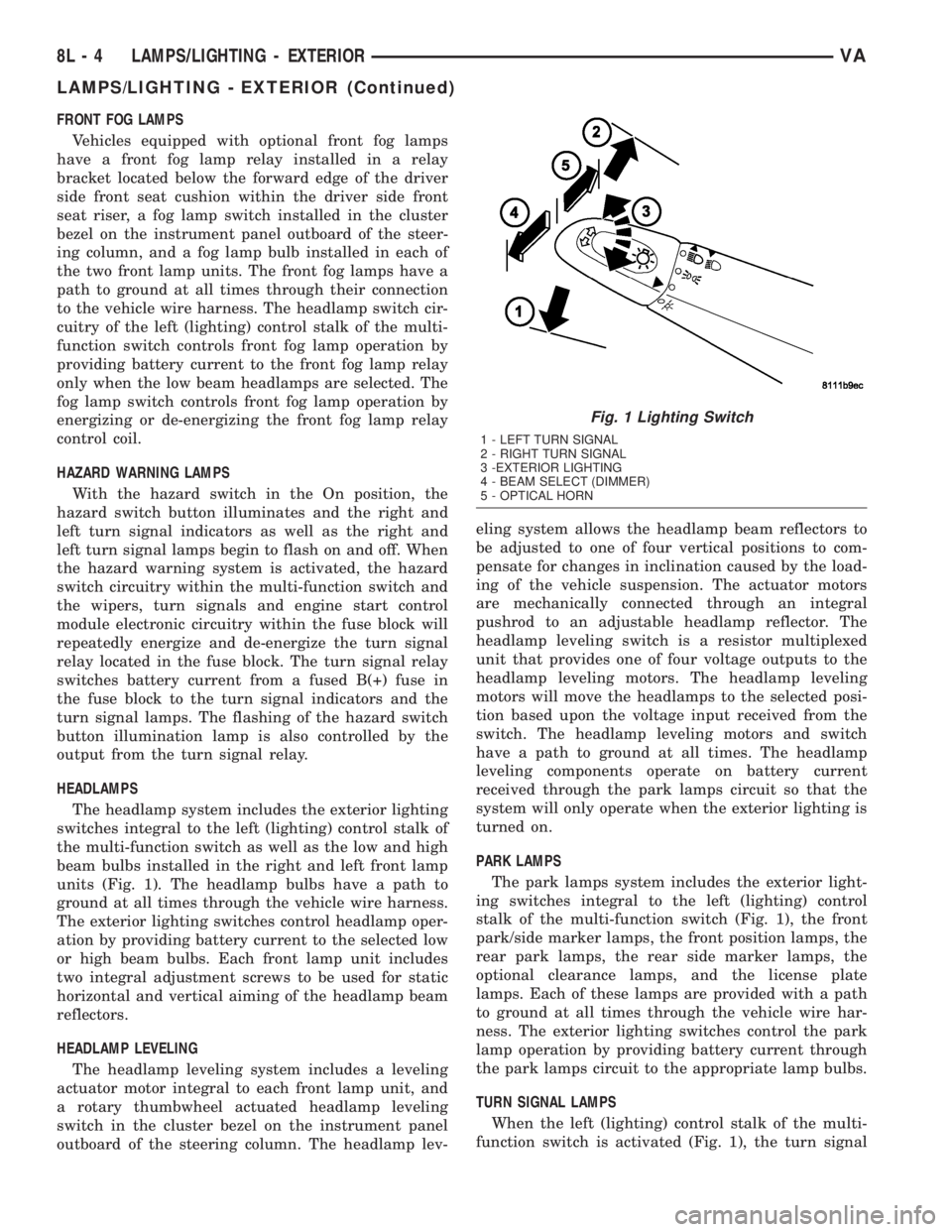
The headlamp system includes the exterior lighting
switches integral to the left (lighting) control stalk of
the multi-function switch as well as the low and high
beam bulbs installed in the right and left front lamp
units (Fig. 1). The headlamp bulbs have a path to
ground at all times through the vehicle wire harness.
The exterior lighting switches control headlamp oper-
ation by providing battery current to the selected low
or high beam bulbs. Each front lamp unit includes
two integral adjustment screws to be used for static
horizontal and vertical aiming of the headlamp beam
reflectors.
HEADLAMP LEVELING
The headlamp leveling system includes a leveling
actuator motor integral to each front lamp unit, and
a rotary thumbwheel actuated headlamp leveling
switch in the cluster bezel on the instrument panel
outboard of the steering column. The headlamp lev-eling system allows the headlamp beam reflectors to
be adjusted to one of four vertical positions to com-
pensate for changes in inclination caused by the load-
ing of the vehicle suspension. The actuator motors
are mechanically connected through an integral
pushrod to an adjustable headlamp reflector. The
headlamp leveling switch is a resistor multiplexed
unit that provides one of four voltage outputs to the
headlamp leveling motors. The headlamp leveling
motors will move the headlamps to the selected posi-
tion based upon the voltage input received from the
switch. The headlamp leveling motors and switch
have a path to ground at all times. The headlamp
leveling components operate on battery current
received through the park lamps circuit so that the
system will only operate when the exterior lighting is
turned on.
PARK LAMPS
The park lamps system includes the exterior light-
ing switches integral to the left (lighting) control
stalk of the multi-function switch (Fig. 1), the front
park/side marker lamps, the front position lamps, the
rear park lamps, the rear side marker lamps, the
optional clearance lamps, and the license plate
lamps. Each of these lamps are provided with a path
to ground at all times through the vehicle wire har-
ness. The exterior lighting switches control the park
lamp operation by providing battery current through
the park lamps circuit to the appropriate lamp bulbs.
TURN SIGNAL LAMPS
When the left (lighting) control stalk of the multi-
function switch is activated (Fig. 1), the turn signal
Fig. 1 Lighting Switch
1 - LEFT TURN SIGNAL
2 - RIGHT TURN SIGNAL
3 -EXTERIOR LIGHTING
4 - BEAM SELECT (DIMMER)
5 - OPTICAL HORN
8L - 4 LAMPS/LIGHTING - EXTERIORVA
LAMPS/LIGHTING - EXTERIOR (Continued)
Page 203 of 1232
system illuminates the selected right or left turn sig-
nal indicator and the turn signal lamps begin to
flash. The turn signal lamps include a bulb integral
to each front lamp unit and each tail lamp unit, as
well as a repeater lamp bulb located on each front
fender above the front wheels. When the turn signal
system is activated, the turn signal switch circuitry
within the multi-function switch and the electronic
circuitry of the wipers, turn signals and engine start
control module within the fuse block will repeatedly
energize and de-energize the turn signal relay
located in the fuse block. The turn signal relay
switches battery current from a fused ignition switch
output fuse in the fuse block to the appropriate turn
signal indicator and turn signal lamps.
The ElectroMechanical Instrument Cluster (EMIC)
contactless relay will generate repetitive, audible
turn signal ªclickº sounds to emulate the sounds of a
conventional electro-mechanical turn signal flasher
at one of two rates to coincide with the flashing of
the turn signals. The slow rate emulates normal turn
signal operation, while the fast rate emulates ªbulb
outº turn signal operation.
SPECIFICATIONS - LAMPS/LIGHTING -
EXTERIOR
BULB SPECIFICATIONS
LAMP BULB
Backup P21W - 12V 21W
Brake & Rear Park P21/5W - 12V 21/5W
Center High Mounted
StopP21W - 12V 21W
Clearance W3W - 12V 3W
Front Fog H1 - 12V 55W
Front Position W5W - 12V 5W
Front Turn, Park & Side
Marker3457 NA - 12V 28/7.5W
Amber Glass
Low Beam Headlamp H7 - 12V 55W
High Beam Headlamp H1 - 12V 55W
License Plate C5W - 12V 5W
Rear Side Marker R5W - 12V 5W
Rear Turn P21W - 12V 21W
Side Repeater W5W - 12V 3W
BACKUP LAMP BULB
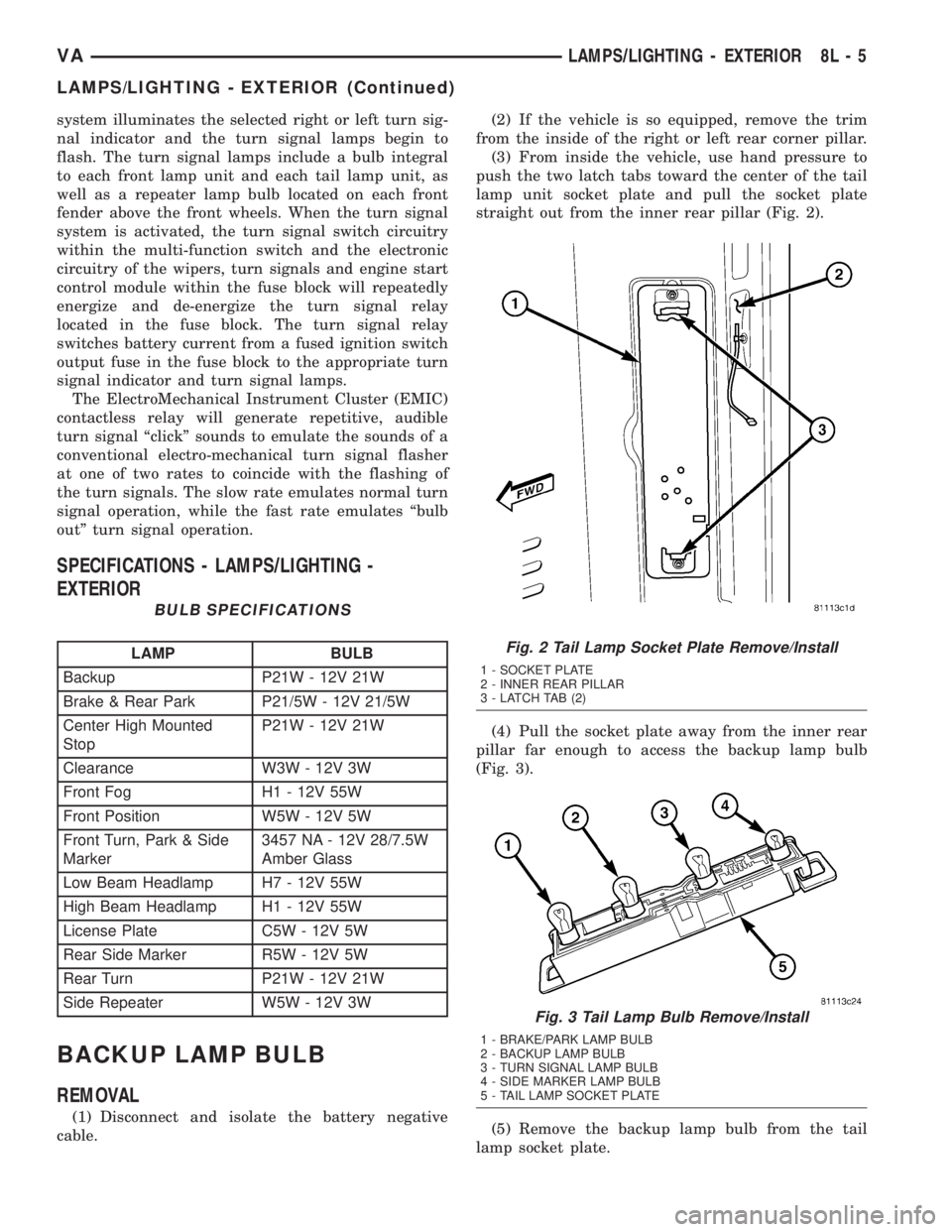
REMOVAL
(1) Disconnect and isolate the battery negative
cable.(2) If the vehicle is so equipped, remove the trim
from the inside of the right or left rear corner pillar.
(3) From inside the vehicle, use hand pressure to
push the two latch tabs toward the center of the tail
lamp unit socket plate and pull the socket plate
straight out from the inner rear pillar (Fig. 2).
(4) Pull the socket plate away from the inner rear
pillar far enough to access the backup lamp bulb
(Fig. 3).
(5) Remove the backup lamp bulb from the tail
lamp socket plate.
Fig. 2 Tail Lamp Socket Plate Remove/Install
1 - SOCKET PLATE
2 - INNER REAR PILLAR
3 - LATCH TAB (2)
Fig. 3 Tail Lamp Bulb Remove/Install
1 - BRAKE/PARK LAMP BULB
2 - BACKUP LAMP BULB
3 - TURN SIGNAL LAMP BULB
4 - SIDE MARKER LAMP BULB
5 - TAIL LAMP SOCKET PLATE
VALAMPS/LIGHTING - EXTERIOR 8L - 5
LAMPS/LIGHTING - EXTERIOR (Continued)
Page 207 of 1232
INSTALLATION
(1) Position the clearance lamp unit close enough
to the vehicle to reconnect the vehicle wire harness
to the bulb holder connector receptacle (Fig. 11).
(2) Position the clearance lamp unit to the vehicle.
(3) Install and tighten the two screws that secure
the clearance lamp unit to the vehicle.
(4) Reconnect the battery negative cable.
DAYTIME RUNNING LAMP
RELAY
REMOVAL
Daytime Running Lamps (DRL) are only used in
vehicles manufactured for the Canadian market,
where this is required equipment. On vehicles
equipped with DRL, a right and a left DRL relay are
each located in a dedicated connector of the vehicle
wire harness. Each connector is snapped into an
opening in a stamped sheet metal bracket which is
secured with screws within the driver side front seat
riser just beneath the seat riser cover panel.
WARNING: ON VEHICLES EQUIPPED WITH AIRBAGS,
DISABLE THE SUPPLEMENTAL RESTRAINT SYSTEM
BEFORE ATTEMPTING ANY STEERING WHEEL,
STEERING COLUMN, DRIVER AIRBAG, PASSENGER
AIRBAG, SEAT BELT TENSIONER, OR INSTRUMENT
PANEL COMPONENT DIAGNOSIS OR SERVICE. DIS-
CONNECT AND ISOLATE THE BATTERY NEGATIVE
(GROUND) CABLE, THEN WAIT TWO MINUTES FOR
THE SYSTEM CAPACITOR TO DISCHARGE BEFORE
PERFORMING FURTHER DIAGNOSIS OR SERVICE.
THIS IS THE ONLY SURE WAY TO DISABLE THE SUP-
PLEMENTAL RESTRAINT SYSTEM. FAILURE TO TAKE
THE PROPER PRECAUTIONS COULD RESULT IN
ACCIDENTAL AIRBAG DEPLOYMENT AND POSSIBLE
PERSONAL INJURY.
(1) Disconnect and isolate the battery negative
cable.
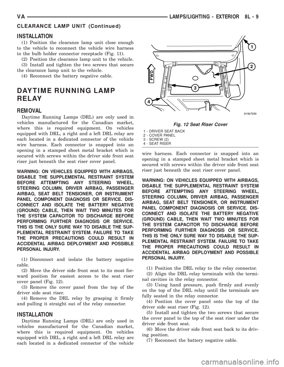
(2) Move the driver side front seat to its most for-
ward position for easiest access to the seat riser
cover panel (Fig. 12).
(3) Remove the cover panel from the top of the
driver side seat riser.
(4) Remove the DRL relay by grasping it firmly
and pulling it straight out of the relay connector.
INSTALLATION
Daytime Running Lamps (DRL) are only used in
vehicles manufactured for the Canadian market,
where this is required equipment. On vehicles
equipped with DRL, a right and a left DRL relay are
each located in a dedicated connector of the vehiclewire harness. Each connector is snapped into an
opening in a stamped sheet metal bracket which is
secured with screws within the driver side front seat
riser just beneath the seat riser cover panel.
WARNING: ON VEHICLES EQUIPPED WITH AIRBAGS,
DISABLE THE SUPPLEMENTAL RESTRAINT SYSTEM
BEFORE ATTEMPTING ANY STEERING WHEEL,
STEERING COLUMN, DRIVER AIRBAG, PASSENGER
AIRBAG, SEAT BELT TENSIONER, OR INSTRUMENT
PANEL COMPONENT DIAGNOSIS OR SERVICE. DIS-
CONNECT AND ISOLATE THE BATTERY NEGATIVE
(GROUND) CABLE, THEN WAIT TWO MINUTES FOR
THE SYSTEM CAPACITOR TO DISCHARGE BEFORE
PERFORMING FURTHER DIAGNOSIS OR SERVICE.
THIS IS THE ONLY SURE WAY TO DISABLE THE SUP-
PLEMENTAL RESTRAINT SYSTEM. FAILURE TO TAKE
THE PROPER PRECAUTIONS COULD RESULT IN
ACCIDENTAL AIRBAG DEPLOYMENT AND POSSIBLE
PERSONAL INJURY.
(1) Position the DRL relay to the relay connector.
(2) Align the DRL relay terminals with the termi-
nal cavities in the relay connector.
(3) Using hand pressure, push firmly and evenly
on the top of the DRL relay until the terminals are
fully seated in the relay connector.
(4) Position the cover panel onto the top of the
driver side seat riser (Fig. 12).
(5) Install and tighten the two screws that secure
the cover panel to the top of the seat riser under the
driver side front seat.
(6) Move the driver side front seat back to its driv-
ing position.
(7) Reconnect the battery negative cable.
Fig. 12 Seat Riser Cover
1 - DRIVER SEAT BACK
2 - COVER PANEL
3 - SCREW (2)
4 - SEAT RISER
VALAMPS/LIGHTING - EXTERIOR 8L - 9
CLEARANCE LAMP UNIT (Continued)
Page 208 of 1232
FOG LAMP BULB
REMOVAL
(1) Disconnect and isolate the battery negative
cable.
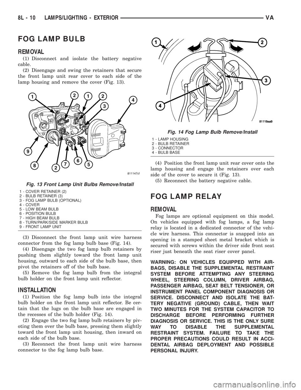
(2) Disengage and swing the retainers that secure
the front lamp unit rear cover to each side of the
lamp housing and remove the cover (Fig. 13).
(3) Disconnect the front lamp unit wire harness
connector from the fog lamp bulb base (Fig. 14).
(4) Disengage the two fog lamp bulb retainers by
pushing them slightly toward the front lamp unit
housing, outward to each side of the bulb base, then
pivot the retainers off of the bulb base.
(5) Remove the fog lamp bulb from the integral
bulb holder on the front lamp unit reflector.
INSTALLATION
(1) Position the fog lamp bulb into the integral
bulb holder on the front lamp unit reflector. Be cer-
tain that the lugs on the bulb base are engaged in
the recesses of the bulb holder (Fig. 14).
(2) Engage the two fog lamp bulb retainers by piv-
oting them over the bulb base, pressing them slightly
toward the front lamp unit housing, then inward on
each side of the bulb base.
(3) Reconnect the front lamp unit wire harness
connector to the fog lamp bulb base.(4) Position the front lamp unit rear cover onto the
lamp housing and engage the retainers over each
side of the cover to secure it (Fig. 13).
(5) Reconnect the battery negative cable.
FOG LAMP RELAY
REMOVAL
Fog lamps are optional equipment on this model.
On vehicles equipped with fog lamps, a fog lamp
relay is located in a dedicated connector of the vehi-
cle wire harness. This connector is snapped into an
opening in a stamped sheet metal bracket which is
secured with screws within the driver side front seat
riser just beneath the seat riser cover panel.
WARNING: ON VEHICLES EQUIPPED WITH AIR-
BAGS, DISABLE THE SUPPLEMENTAL RESTRAINT
SYSTEM BEFORE ATTEMPTING ANY STEERING
WHEEL, STEERING COLUMN, DRIVER AIRBAG,
PASSENGER AIRBAG, SEAT BELT TENSIONER, OR
INSTRUMENT PANEL COMPONENT DIAGNOSIS OR
SERVICE. DISCONNECT AND ISOLATE THE BAT-
TERY NEGATIVE (GROUND) CABLE, THEN WAIT
TWO MINUTES FOR THE SYSTEM CAPACITOR TO
DISCHARGE BEFORE PERFORMING FURTHER
DIAGNOSIS OR SERVICE. THIS IS THE ONLY SURE
WAY TO DISABLE THE SUPPLEMENTAL
RESTRAINT SYSTEM. FAILURE TO TAKE THE
PROPER PRECAUTIONS COULD RESULT IN ACCI-
DENTAL AIRBAG DEPLOYMENT AND POSSIBLE
PERSONAL INJURY.
Fig. 13 Front Lamp Unit Bulbs Remove/Install
1 - COVER RETAINER (2)
2 - BULB RETAINER (3)
3 - FOG LAMP BULB (OPTIONAL)
4 - COVER
5 - LOW BEAM BULB
6 - POSITION BULB
7 - HIGH BEAM BULB
8 - TURN/PARK/SIDE MARKER BULB
9 - FRONT LAMP UNIT
Fig. 14 Fog Lamp Bulb Remove/Install
1 - LAMP HOUSING
2 - BULB RETAINER
3 - CONNECTOR
4 - BULB BASE
8L - 10 LAMPS/LIGHTING - EXTERIORVA
Page 209 of 1232
(1) Disconnect and isolate the battery negative
cable.
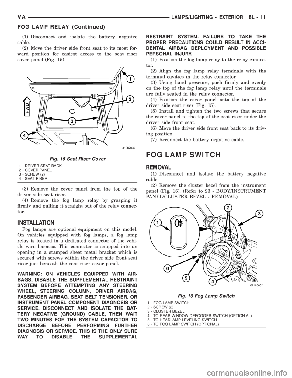
(2) Move the driver side front seat to its most for-
ward position for easiest access to the seat riser
cover panel (Fig. 15).
(3) Remove the cover panel from the top of the
driver side seat riser.
(4) Remove the fog lamp relay by grasping it
firmly and pulling it straight out of the relay connec-
tor.
INSTALLATION
Fog lamps are optional equipment on this model.
On vehicles equipped with fog lamps, a fog lamp
relay is located in a dedicated connector of the vehi-
cle wire harness. This connector is snapped into an
opening in a stamped sheet metal bracket which is
secured with screws within the driver side front seat
riser just beneath the seat riser cover panel.
WARNING: ON VEHICLES EQUIPPED WITH AIR-
BAGS, DISABLE THE SUPPLEMENTAL RESTRAINT
SYSTEM BEFORE ATTEMPTING ANY STEERING
WHEEL, STEERING COLUMN, DRIVER AIRBAG,
PASSENGER AIRBAG, SEAT BELT TENSIONER, OR
INSTRUMENT PANEL COMPONENT DIAGNOSIS OR
SERVICE. DISCONNECT AND ISOLATE THE BAT-
TERY NEGATIVE (GROUND) CABLE, THEN WAIT
TWO MINUTES FOR THE SYSTEM CAPACITOR TO
DISCHARGE BEFORE PERFORMING FURTHER
DIAGNOSIS OR SERVICE. THIS IS THE ONLY SURE
WAY TO DISABLE THE SUPPLEMENTALRESTRAINT SYSTEM. FAILURE TO TAKE THE
PROPER PRECAUTIONS COULD RESULT IN ACCI-
DENTAL AIRBAG DEPLOYMENT AND POSSIBLE
PERSONAL INJURY.
(1) Position the fog lamp relay to the relay connec-
tor.
(2) Align the fog lamp relay terminals with the
terminal cavities in the relay connector.
(3) Using hand pressure, push firmly and evenly
on the top of the fog lamp relay until the terminals
are fully seated in the relay connector.
(4) Position the cover panel onto the top of the
driver side seat riser (Fig. 15).
(5) Install and tighten the two screws that secure
the cover panel to the top of the seat riser under the
driver side front seat.
(6) Move the driver side front seat back to its driv-
ing position.
(7) Reconnect the battery negative cable.
FOG LAMP SWITCH
REMOVAL
(1) Disconnect and isolate the battery negative
cable.
(2) Remove the cluster bezel from the instrument
panel (Fig. 16). (Refer to 23 - BODY/INSTRUMENT
PANEL/CLUSTER BEZEL - REMOVAL).
Fig. 15 Seat Riser Cover
1 - DRIVER SEAT BACK
2 - COVER PANEL
3 - SCREW (2)
4 - SEAT RISER
Fig. 16 Fog Lamp Switch
1 - FOG LAMP SWITCH
2 - SCREW (2)
3 - CLUSTER BEZEL
4 - TO REAR WINDOW DEFOGGER SWITCH (OPTION AL)
5 - TO HEADLAMP LEVELING SWITCH
6 - TO FOG LAMP SWITCH (OPTIONAL)
VALAMPS/LIGHTING - EXTERIOR 8L - 11
FOG LAMP RELAY (Continued)