2005 MERCEDES-BENZ SPRINTER fuel system
[x] Cancel search: fuel systemPage 750 of 1232
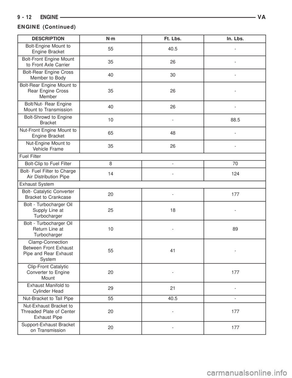
DESCRIPTION N´m Ft. Lbs. In. Lbs.
Bolt-Engine Mount to
Engine Bracket55 40.5 -
Bolt-Front Engine Mount
to Front Axle Carrier35 26 -
Bolt-Rear Engine Cross
Member to Body40 30 -
Bolt-Rear Engine Mount to
Rear Engine Cross
Member35 26 -
Bolt/Nut- Rear Engine
Mount to Transmission40 26 -
Bolt-Shrowd to Engine
Bracket10 - 88.5
Nut-Front Engine Mount to
Engine Bracket65 48 -
Nut-Engine Mount to
Vehicle Frame35 26 -
Fuel Filter
Bolt-Clip to Fuel Filter 8 - 70
Bolt- Fuel Filter to Charge
Air Distribution Pipe14 - 124
Exhaust System
Bolt- Catalytic Converter
Bracket to Crankcase20 - 177
Bolt - Turbocharger Oil
Supply Line at
Turbocharger25 18 -
Bolt - Turbocharger Oil
Return Line at
Turbocharger10 - 89
Clamp-Connection
Between Front Exhaust
Pipe and Rear Exhaust
System55 41 -
Clip-Front Catalytic
Converter to Engine
Mount20 - 177
Exhaust Manifold to
Cylinder Head29 21 -
Nut-Bracket to Tail Pipe 55 40.5 -
Nut-Exhaust Bracket to
Threaded Plate of Center
Exhaust Pipe20 - 177
Support-Exhaust Bracket
on Transmission20 - 177
9 - 12 ENGINEVA
ENGINE (Continued)
Page 752 of 1232
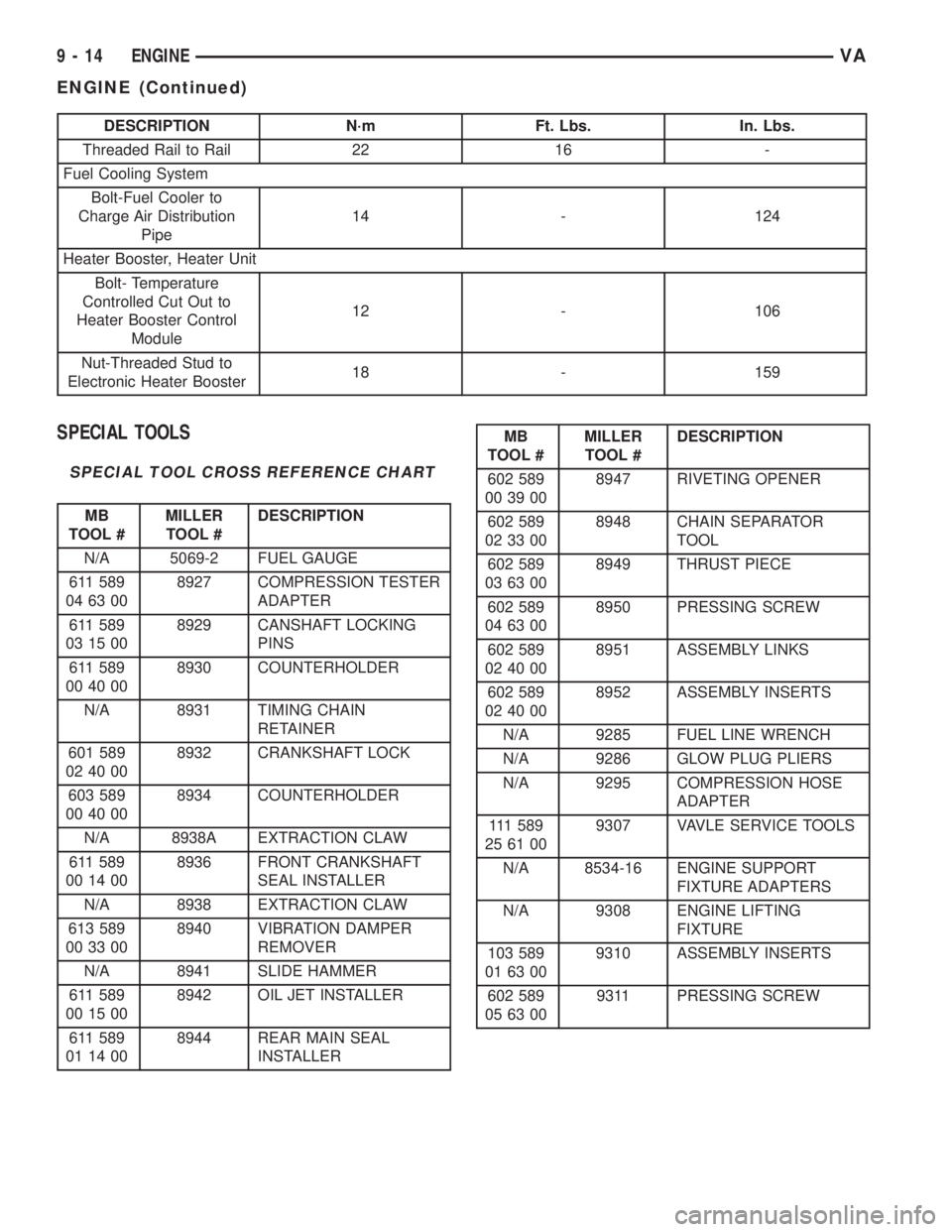
DESCRIPTION N´m Ft. Lbs. In. Lbs.
Threaded Rail to Rail 22 16 -
Fuel Cooling System
Bolt-Fuel Cooler to
Charge Air Distribution
Pipe14 - 124
Heater Booster, Heater Unit
Bolt- Temperature
Controlled Cut Out to
Heater Booster Control
Module12 - 106
Nut-Threaded Stud to
Electronic Heater Booster18 - 159
SPECIAL TOOLS
SPECIAL TOOL CROSS REFERENCE CHART
MB
TOOL #MILLER
TOOL #DESCRIPTION
N/A 5069-2 FUEL GAUGE
611 589
04 63 008927 COMPRESSION TESTER
ADAPTER
611 589
03 15 008929 CANSHAFT LOCKING
PINS
611 589
00 40 008930 COUNTERHOLDER
N/A 8931 TIMING CHAIN
RETAINER
601 589
02 40 008932 CRANKSHAFT LOCK
603 589
00 40 008934 COUNTERHOLDER
N/A 8938A EXTRACTION CLAW
611 589
00 14 008936 FRONT CRANKSHAFT
SEAL INSTALLER
N/A 8938 EXTRACTION CLAW
613 589
00 33 008940 VIBRATION DAMPER
REMOVER
N/A 8941 SLIDE HAMMER
611 589
00 15 008942 OIL JET INSTALLER
611 589
01 14 008944 REAR MAIN SEAL
INSTALLER
MB
TOOL #MILLER
TOOL #DESCRIPTION
602 589
00 39 008947 RIVETING OPENER
602 589
02 33 008948 CHAIN SEPARATOR
TOOL
602 589
03 63 008949 THRUST PIECE
602 589
04 63 008950 PRESSING SCREW
602 589
02 40 008951 ASSEMBLY LINKS
602 589
02 40 008952 ASSEMBLY INSERTS
N/A 9285 FUEL LINE WRENCH
N/A 9286 GLOW PLUG PLIERS
N/A 9295 COMPRESSION HOSE
ADAPTER
111 5 8 9
25 61 009307 VAVLE SERVICE TOOLS
N/A 8534-16 ENGINE SUPPORT
FIXTURE ADAPTERS
N/A 9308 ENGINE LIFTING
FIXTURE
103 589
01 63 009310 ASSEMBLY INSERTS
602 589
05 63 009311 PRESSING SCREW
9 - 14 ENGINEVA
ENGINE (Continued)
Page 758 of 1232
AIR CLEANER ELEMENT
REMOVAL
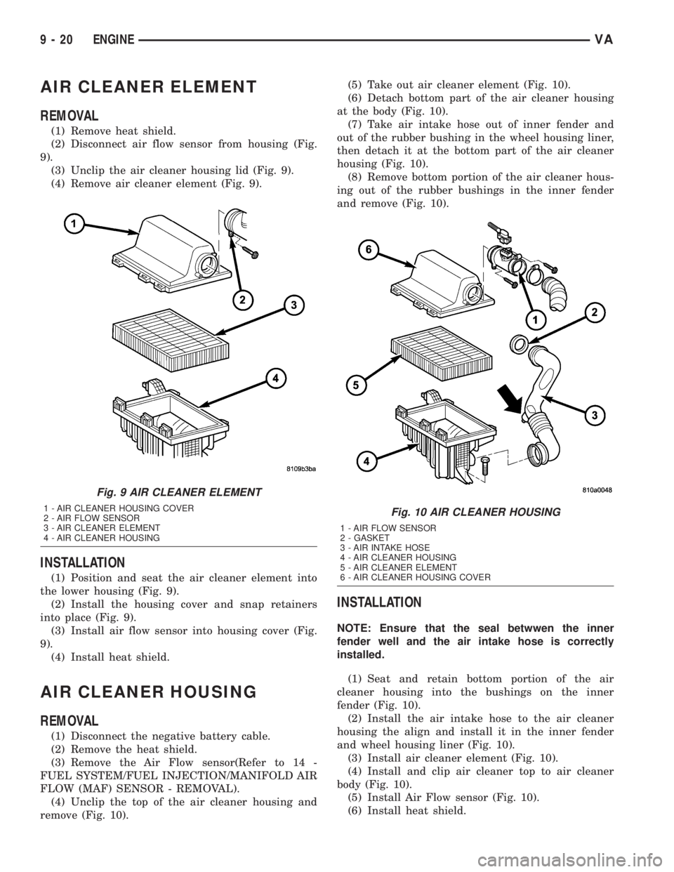
(1) Remove heat shield.
(2) Disconnect air flow sensor from housing (Fig.
9).
(3) Unclip the air cleaner housing lid (Fig. 9).
(4) Remove air cleaner element (Fig. 9).
INSTALLATION
(1) Position and seat the air cleaner element into
the lower housing (Fig. 9).
(2) Install the housing cover and snap retainers
into place (Fig. 9).
(3) Install air flow sensor into housing cover (Fig.
9).
(4) Install heat shield.
AIR CLEANER HOUSING
REMOVAL
(1) Disconnect the negative battery cable.
(2) Remove the heat shield.
(3) Remove the Air Flow sensor(Refer to 14 -
FUEL SYSTEM/FUEL INJECTION/MANIFOLD AIR
FLOW (MAF) SENSOR - REMOVAL).
(4) Unclip the top of the air cleaner housing and
remove (Fig. 10).(5) Take out air cleaner element (Fig. 10).
(6) Detach bottom part of the air cleaner housing
at the body (Fig. 10).
(7) Take air intake hose out of inner fender and
out of the rubber bushing in the wheel housing liner,
then detach it at the bottom part of the air cleaner
housing (Fig. 10).
(8) Remove bottom portion of the air cleaner hous-
ing out of the rubber bushings in the inner fender
and remove (Fig. 10).
INSTALLATION
NOTE: Ensure that the seal betwwen the inner
fender well and the air intake hose is correctly
installed.
(1) Seat and retain bottom portion of the air
cleaner housing into the bushings on the inner
fender (Fig. 10).
(2) Install the air intake hose to the air cleaner
housing the align and install it in the inner fender
and wheel housing liner (Fig. 10).
(3) Install air cleaner element (Fig. 10).
(4) Install and clip air cleaner top to air cleaner
body (Fig. 10).
(5) Install Air Flow sensor (Fig. 10).
(6) Install heat shield.
Fig. 9 AIR CLEANER ELEMENT
1 - AIR CLEANER HOUSING COVER
2 - AIR FLOW SENSOR
3 - AIR CLEANER ELEMENT
4 - AIR CLEANER HOUSINGFig. 10 AIR CLEANER HOUSING
1 - AIR FLOW SENSOR
2 - GASKET
3 - AIR INTAKE HOSE
4 - AIR CLEANER HOUSING
5 - AIR CLEANER ELEMENT
6 - AIR CLEANER HOUSING COVER
9 - 20 ENGINEVA
Page 760 of 1232
REMOVAL
REMOVAL - CYLINDER HEAD
(1) Disconnect negative battery cable.
(2) Position piston of cylinder #1 to ignition TDC.
(3) Raise and support vehicle.
(4) Install retaining lock # 8932 for crankshaft/
starter ring gear.
WARNING: RISK OF INJURY TO SKIN AND EYES
FROM SCALDING COOLANT. DO NOT OPEN COOL-
ING SYSTEM UNLESS TEMPERATURE IS BELOW
90ÉC (194ÉF). OPEN CAP SLOWLY TO RELEASE
PRESSURE. STORE COOLANT IN APPROVED CON-
TAINER ONLY. WEAR PROTECTIVE GLOVES,
CLOTHING AND EYE WEAR.
(5) Drain cooling system at radiator and crank-
case(Refer to 7 - COOLING/ENGINE/COOLANT -
STANDARD PROCEDURE).
(6) Lower vehicle.(7) Remove engine cover. (Refer to 9 - ENGINE
COVER- REMOVAL).
(8) Remove camshafts (Refer to 9 - ENGINE/CYL-
INDER HEAD/CAMSHAFT(S) - REMOVAL).
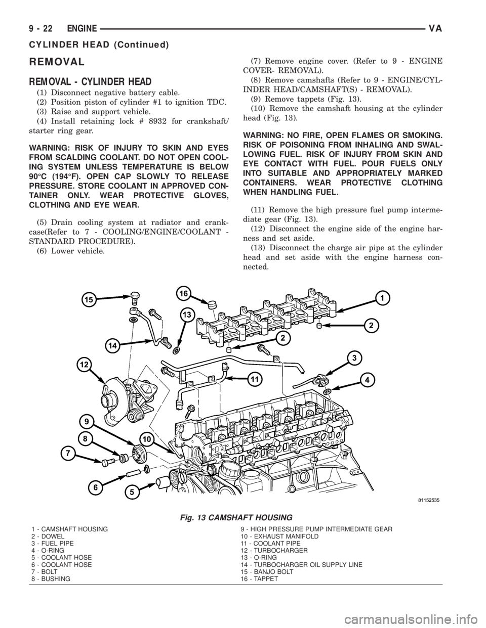
(9) Remove tappets (Fig. 13).
(10) Remove the camshaft housing at the cylinder
head (Fig. 13).
WARNING: NO FIRE, OPEN FLAMES OR SMOKING.
RISK OF POISONING FROM INHALING AND SWAL-
LOWING FUEL. RISK OF INJURY FROM SKIN AND
EYE CONTACT WITH FUEL. POUR FUELS ONLY
INTO SUITABLE AND APPROPRIATELY MARKED
CONTAINERS. WEAR PROTECTIVE CLOTHING
WHEN HANDLING FUEL.
(11) Remove the high pressure fuel pump interme-
diate gear (Fig. 13).
(12) Disconnect the engine side of the engine har-
ness and set aside.
(13) Disconnect the charge air pipe at the cylinder
head and set aside with the engine harness con-
nected.
Fig. 13 CAMSHAFT HOUSING
1 - CAMSHAFT HOUSING 9 - HIGH PRESSURE PUMP INTERMEDIATE GEAR
2 - DOWEL 10 - EXHAUST MANIFOLD
3 - FUEL PIPE 11 - COOLANT PIPE
4 - O-RING 12 - TURBOCHARGER
5 - COOLANT HOSE 13 - O-RING
6 - COOLANT HOSE 14 - TURBOCHARGER OIL SUPPLY LINE
7 - BOLT 15 - BANJO BOLT
8 - BUSHING 16 - TAPPET
9 - 22 ENGINEVA
CYLINDER HEAD (Continued)
Page 761 of 1232
(14) Disconnect the turbocharger oil supply line at
the cylinder head and turbocharger (Fig. 13).
(15) Disconnect the turbocharger at the exhaust
manifold (Fig. 13).
(16) Unbolt the transmission dipstick tube from
the cylinder head (Fig. 13).
(17) Disconnect the upper radiator hose and by
pass hose at the thermostat housing (Fig. 13).
NOTE: Capture any fuel spillage when disconnect-
ing fuel lines.
(18) Disconnect the fuel line at the rear of the fuel
rail (Fig. 13).
(19) Remove upper timing case to cylinder head
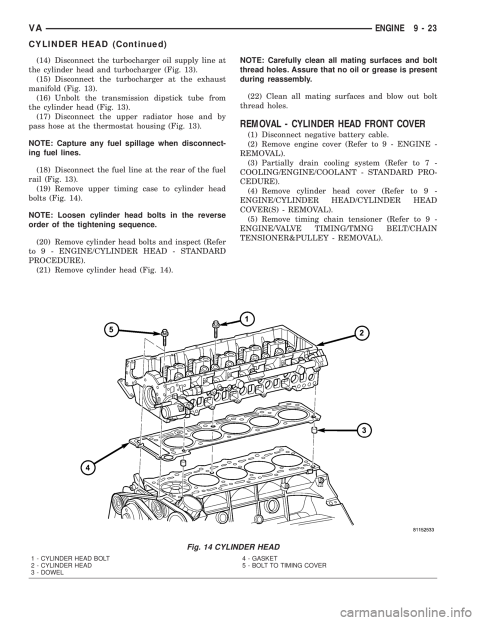
bolts (Fig. 14).
NOTE: Loosen cylinder head bolts in the reverse
order of the tightening sequence.
(20) Remove cylinder head bolts and inspect (Refer
to 9 - ENGINE/CYLINDER HEAD - STANDARD
PROCEDURE).
(21) Remove cylinder head (Fig. 14).NOTE: Carefully clean all mating surfaces and bolt
thread holes. Assure that no oil or grease is present
during reassembly.
(22) Clean all mating surfaces and blow out bolt
thread holes.
REMOVAL - CYLINDER HEAD FRONT COVER
(1) Disconnect negative battery cable.
(2) Remove engine cover (Refer to 9 - ENGINE -
REMOVAL).
(3) Partially drain cooling system (Refer to 7 -
COOLING/ENGINE/COOLANT - STANDARD PRO-
CEDURE).
(4) Remove cylinder head cover (Refer to 9 -
ENGINE/CYLINDER HEAD/CYLINDER HEAD
COVER(S) - REMOVAL).
(5) Remove timing chain tensioner (Refer to 9 -
ENGINE/VALVE TIMING/TMNG BELT/CHAIN
TENSIONER&PULLEY - REMOVAL).
Fig. 14 CYLINDER HEAD
1 - CYLINDER HEAD BOLT
2 - CYLINDER HEAD
3 - DOWEL4 - GASKET
5 - BOLT TO TIMING COVER
VAENGINE 9 - 23
CYLINDER HEAD (Continued)
Page 762 of 1232
WARNING: NO FIRE, OPEN FLAMES OR SMOKING.
SERVICE VEHICLE IN WELL VENTILATED AREAS
AND AVOID IGNITION SOURCES. RISK OF POISON-
ING FROM INHALING AND SWALLOWING FUEL.
RISK OF INJURY FROM SKIN AND EYE CONTACT
WITH FUEL. POUR FUELS ONLY INTO SUITABLE
AND APPROPRIATELY MARKED CONTAINERS.
WEAR PROTECTIVE CLOTHING WHEN HANDLING
FUEL.
(6) Remove low pressure pump (Refer to 14 -
FUEL SYSTEM/FUEL DELIVERY/FUEL INJEC-
TION PUMP - REMOVAL).
(7) Remove vacuum pump (Refer to 9 - ENGINE/
ENGINE BLOCK/INTERNAL VACUUM PUMP -
REMOVAL).
(8) Remove bolts attaching front cover.
NOTE: Lower portion of front cover is sealed with
RTV sealant. Carefully tug at front cover until it
loosens from cylinder head.
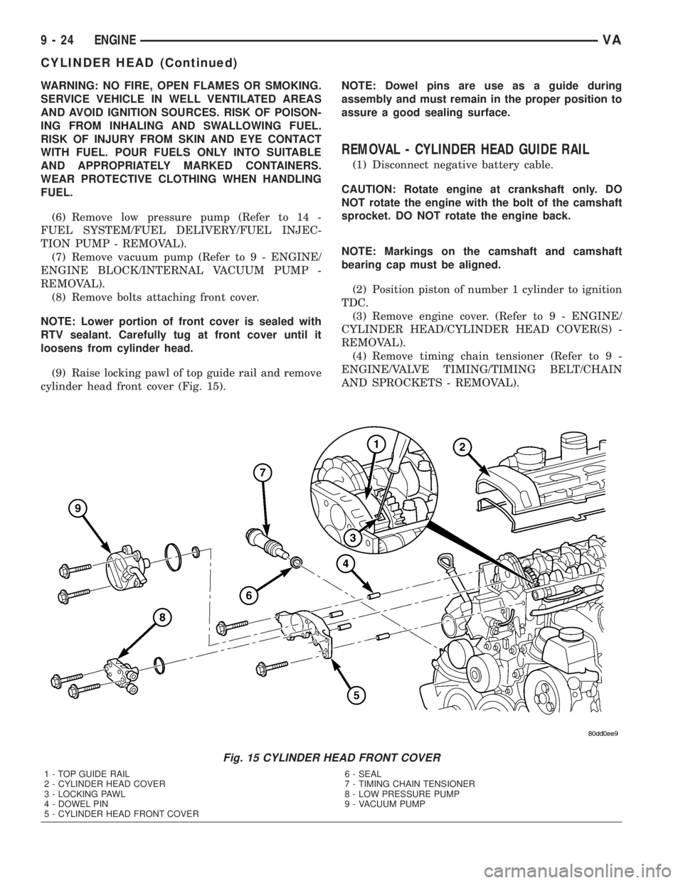
(9) Raise locking pawl of top guide rail and remove
cylinder head front cover (Fig. 15).NOTE: Dowel pins are use as a guide during
assembly and must remain in the proper position to
assure a good sealing surface.
REMOVAL - CYLINDER HEAD GUIDE RAIL
(1) Disconnect negative battery cable.
CAUTION: Rotate engine at crankshaft only. DO
NOT rotate the engine with the bolt of the camshaft
sprocket. DO NOT rotate the engine back.
NOTE: Markings on the camshaft and camshaft
bearing cap must be aligned.
(2) Position piston of number 1 cylinder to ignition
TDC.
(3) Remove engine cover. (Refer to 9 - ENGINE/
CYLINDER HEAD/CYLINDER HEAD COVER(S) -
REMOVAL).
(4) Remove timing chain tensioner (Refer to 9 -
ENGINE/VALVE TIMING/TIMING BELT/CHAIN
AND SPROCKETS - REMOVAL).
Fig. 15 CYLINDER HEAD FRONT COVER
1 - TOP GUIDE RAIL
2 - CYLINDER HEAD COVER
3 - LOCKING PAWL
4 - DOWEL PIN
5 - CYLINDER HEAD FRONT COVER6 - SEAL
7 - TIMING CHAIN TENSIONER
8 - LOW PRESSURE PUMP
9 - VACUUM PUMP
9 - 24 ENGINEVA
CYLINDER HEAD (Continued)
Page 763 of 1232
(5) Carefully raise locking pawl of top slide rail
and remove front cover at cylinder head (Fig. 15).
(6) Insert a locking pin through 1st camshaft bear-
ing cap into the hole in the inlet camshaft sprocket.
(7) Counter hold the camshaft with an open end
wrench to avoid damage and unbolt driver of inlet
camshaft sprocket.
(8) Remove top guide rail.
INSTALLATION
INSTALLATION - CYLINDER HEAD
WARNING: (Refer to 14 - FUEL SYSTEM - WARN-
ING)
NOTE: Thoroughly clean all mating surfaces with
appropriate solvents and blow out bolt holes, to
assure that no grease or oil is present during reas-
sembly.
NOTE: If piston or connecting rods have been
replaced, measure piston protrusion.
NOTE: Check facing cylinder head contact surface.
(1) Position the cylinder head and gasket properly
on engine using the dowel pins as guide (Fig. 14).
NOTE: Inspect all cylinder head bolts for defects
and stretching before installation (Refer to 9 -
ENGINE/CYLINDER HEAD - STANDARD PROCE-
DURE).
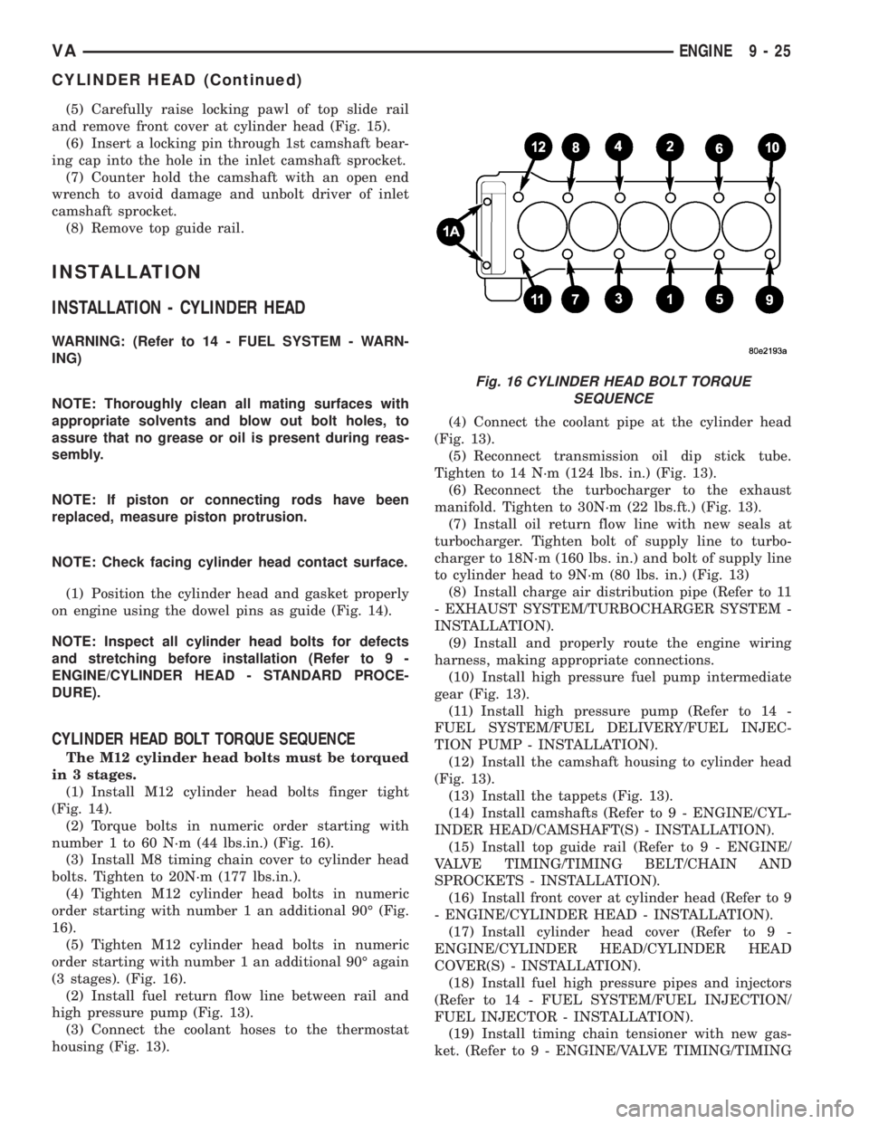
CYLINDER HEAD BOLT TORQUE SEQUENCE
The M12 cylinder head bolts must be torqued
in 3 stages.
(1) Install M12 cylinder head bolts finger tight
(Fig. 14).
(2) Torque bolts in numeric order starting with
number 1 to 60 N´m (44 lbs.in.) (Fig. 16).
(3) Install M8 timing chain cover to cylinder head
bolts. Tighten to 20N´m (177 lbs.in.).
(4) Tighten M12 cylinder head bolts in numeric
order starting with number 1 an additional 90É (Fig.
16).
(5) Tighten M12 cylinder head bolts in numeric
order starting with number 1 an additional 90É again
(3 stages). (Fig. 16).
(2) Install fuel return flow line between rail and
high pressure pump (Fig. 13).
(3) Connect the coolant hoses to the thermostat
housing (Fig. 13).(4) Connect the coolant pipe at the cylinder head
(Fig. 13).
(5) Reconnect transmission oil dip stick tube.
Tighten to 14 N´m (124 lbs. in.) (Fig. 13).
(6) Reconnect the turbocharger to the exhaust
manifold. Tighten to 30N´m (22 lbs.ft.) (Fig. 13).
(7) Install oil return flow line with new seals at
turbocharger. Tighten bolt of supply line to turbo-
charger to 18N´m (160 lbs. in.) and bolt of supply line
to cylinder head to 9N´m (80 lbs. in.) (Fig. 13)
(8) Install charge air distribution pipe (Refer to 11
- EXHAUST SYSTEM/TURBOCHARGER SYSTEM -
INSTALLATION).
(9) Install and properly route the engine wiring
harness, making appropriate connections.
(10) Install high pressure fuel pump intermediate
gear (Fig. 13).
(11) Install high pressure pump (Refer to 14 -
FUEL SYSTEM/FUEL DELIVERY/FUEL INJEC-
TION PUMP - INSTALLATION).
(12) Install the camshaft housing to cylinder head
(Fig. 13).
(13) Install the tappets (Fig. 13).
(14) Install camshafts (Refer to 9 - ENGINE/CYL-
INDER HEAD/CAMSHAFT(S) - INSTALLATION).
(15) Install top guide rail (Refer to 9 - ENGINE/
VALVE TIMING/TIMING BELT/CHAIN AND
SPROCKETS - INSTALLATION).
(16) Install front cover at cylinder head (Refer to 9
- ENGINE/CYLINDER HEAD - INSTALLATION).
(17) Install cylinder head cover (Refer to 9 -
ENGINE/CYLINDER HEAD/CYLINDER HEAD
COVER(S) - INSTALLATION).
(18) Install fuel high pressure pipes and injectors
(Refer to 14 - FUEL SYSTEM/FUEL INJECTION/
FUEL INJECTOR - INSTALLATION).
(19) Install timing chain tensioner with new gas-
ket. (Refer to 9 - ENGINE/VALVE TIMING/TIMING
Fig. 16 CYLINDER HEAD BOLT TORQUE
SEQUENCE
VAENGINE 9 - 25
CYLINDER HEAD (Continued)
Page 764 of 1232
BELT/CHAIN AND SPROCKETS - INSTALLATION)
Tighten to 80N´m (59 lbs.ft.).
(20) Remove retaining lock for crankshaft/starter
ring gear.
(21) Install air intake tube at turbocharger (Refer
to 11 - EXHAUST SYSTEM/TURBOCHARGER SYS-
TEM - INSTALLATION).
(22) Install engine cover (Refer to 9 - ENGINE -
INSTALLATION).
NOTE: DO NOT pressure test cooling system until
engine has reached operating temperature.
(23) Refill cooling system with proper coolant mix-
ture to proper level (Refer to 7 - COOLING/ENGINE/
COOLANT - STANDARD PROCEDURE).
(24) Connect negative battery cable.
WARNING: USE EXTREME CAUTION WHEN THE
ENGINE IS OPERATING. DO NOT STAND IN A
DIRECT LINE WITH THE FAN. DO NOT PUT YOUR
HANDS NEAR THE PULLEYS, BELTS OR FAN. DO
NOT WEAR LOOSE CLOTHES.
(25) Start engine and inspect for leaks. Care must
be taken to observe the fuel system warning (Refer to
14 - FUEL SYSTEM - WARNING)
INSTALLATION - CYLINDER HEAD FRONT
COVER
NOTE: Thoroughly clean all mating surfaces with
appropriate solvents to assure that no grease or oil
is present during reassembly.
NOTE: Dowel pins are used as a guide during
assembly and must remain in the proper position to
assure a good sealing surface.
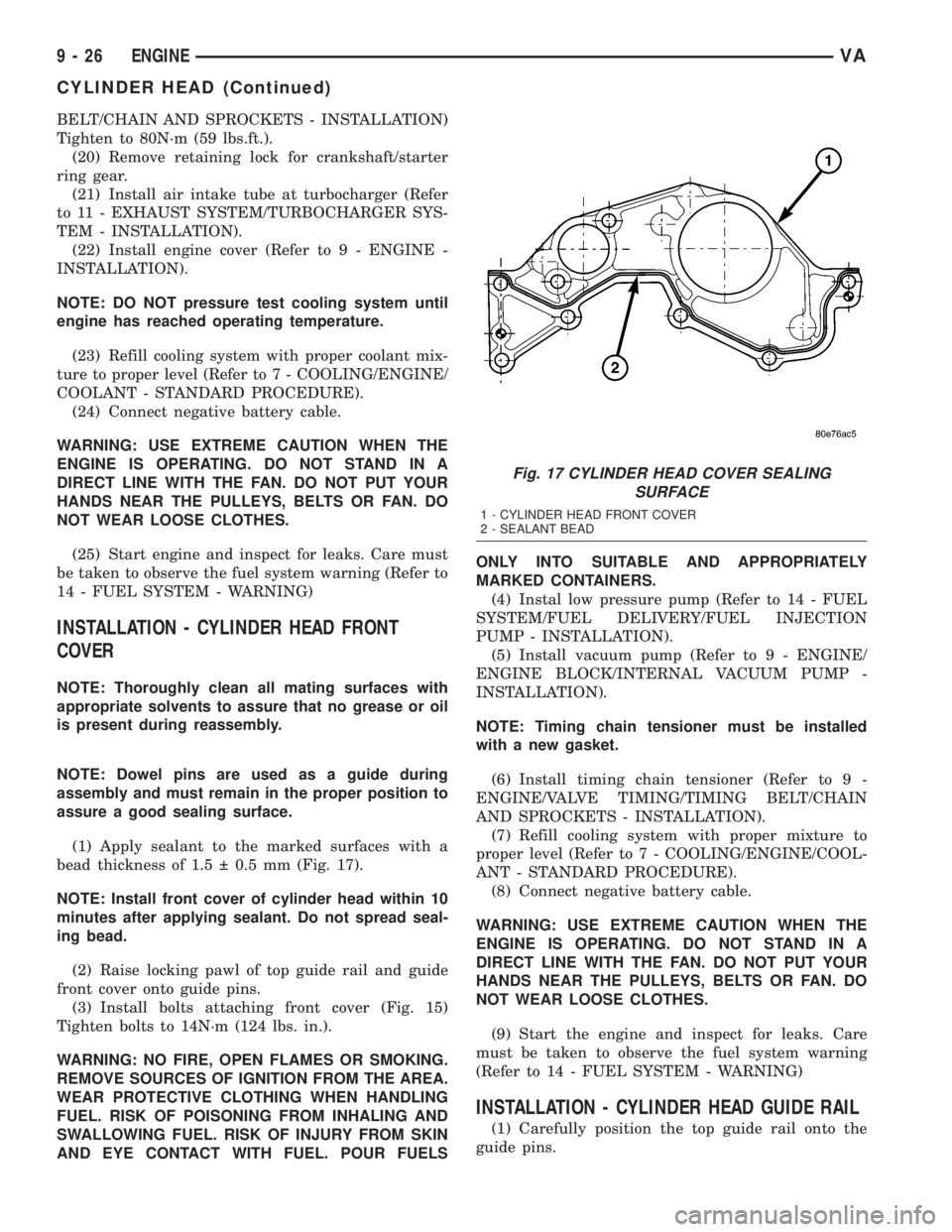
(1) Apply sealant to the marked surfaces with a
bead thickness of 1.5 0.5 mm (Fig. 17).
NOTE: Install front cover of cylinder head within 10
minutes after applying sealant. Do not spread seal-
ing bead.
(2) Raise locking pawl of top guide rail and guide
front cover onto guide pins.
(3) Install bolts attaching front cover (Fig. 15)
Tighten bolts to 14N´m (124 lbs. in.).
WARNING: NO FIRE, OPEN FLAMES OR SMOKING.
REMOVE SOURCES OF IGNITION FROM THE AREA.
WEAR PROTECTIVE CLOTHING WHEN HANDLING
FUEL. RISK OF POISONING FROM INHALING AND
SWALLOWING FUEL. RISK OF INJURY FROM SKIN
AND EYE CONTACT WITH FUEL. POUR FUELSONLY INTO SUITABLE AND APPROPRIATELY
MARKED CONTAINERS.
(4) Instal low pressure pump (Refer to 14 - FUEL
SYSTEM/FUEL DELIVERY/FUEL INJECTION
PUMP - INSTALLATION).
(5) Install vacuum pump (Refer to 9 - ENGINE/
ENGINE BLOCK/INTERNAL VACUUM PUMP -
INSTALLATION).
NOTE: Timing chain tensioner must be installed
with a new gasket.
(6) Install timing chain tensioner (Refer to 9 -
ENGINE/VALVE TIMING/TIMING BELT/CHAIN
AND SPROCKETS - INSTALLATION).
(7) Refill cooling system with proper mixture to
proper level (Refer to 7 - COOLING/ENGINE/COOL-
ANT - STANDARD PROCEDURE).
(8) Connect negative battery cable.
WARNING: USE EXTREME CAUTION WHEN THE
ENGINE IS OPERATING. DO NOT STAND IN A
DIRECT LINE WITH THE FAN. DO NOT PUT YOUR
HANDS NEAR THE PULLEYS, BELTS OR FAN. DO
NOT WEAR LOOSE CLOTHES.
(9) Start the engine and inspect for leaks. Care
must be taken to observe the fuel system warning
(Refer to 14 - FUEL SYSTEM - WARNING)
INSTALLATION - CYLINDER HEAD GUIDE RAIL
(1) Carefully position the top guide rail onto the
guide pins.
Fig. 17 CYLINDER HEAD COVER SEALING
SURFACE
1 - CYLINDER HEAD FRONT COVER
2 - SEALANT BEAD
9 - 26 ENGINEVA
CYLINDER HEAD (Continued)