2005 MERCEDES-BENZ SPRINTER check engine
[x] Cancel search: check enginePage 122 of 1232
OPERATION
The central timer module (CTM) monitors many
hard wired switch and sensor inputs as well as those
resources it shares with other modules in the vehicle
through its communication over the programmable
communications interface (PCI) data bus network.
The internal programming and all of these inputs
allow the CTM to determine the tasks it needs to
perform and their priorities, as well as both the stan-
dard and optional features that it should provide.
The CTM then performs those tasks and provides
those features through both PCI data bus communi-
cation with other modules and hard wired outputs
through a number of driver circuits, relays, and
actuators.These outputs allow the CTM the ability to
control numerous accessory systems in the vehicle.
The CTM monitors its own internal circuitry as
well as many of its input and output circuits, and
will store a Diagnostic Trouble Code (DTC) in elec-
tronic memory for any failure it detects. These DTCs
can be retrieved and diagnosed using a DRBIIItscan
tool. Refer to the appropriate diagnostic information.
HARD WIRED INPUTS
The hard wired inputs to the CTM include the fol-
lowing:
²Fused B(+)
²Fused ignition switch output (run-acc)
²Fused ignition switch output (run-start)
²Ground
²Key-in ignition switch sense
²Sliding door switch sense
²Passenger door switch sense
²Driver door switch sense
²PCI bus circuit
HARD WIRED OUTPUTS
The hard wired outputs of the CTM include the fol-
lowing:
²Door lock relay output
²Door unlock relay output
²VTSS indicator driver
MESSAGING
The CTM uses the following messages received
from other electronic modules over the PCI data bus:
²Airbag Deploy (ACM)
²Beep request (CMTC)
²Charging System Failure (PCM)
²Chime request (EMIC)
²Engine RPM (PCM)
²OK to Arm VTSS (PCM)
²Security indicator request (SKIM)
²System Voltage (PCM)
²Valid/Invalid Key (SKIM)
²Vehicle Distance (PCM)²Vehicle Speed (PCM)DIAGNOSIS AND TESTING - CENTRAL TIMER
MODULE
WARNING: ON VEHICLES EQUIPPED WITH AIR-
BAGS, DISABLE THE AIRBAG SYSTEM BEFORE
ATTEMPTING ANY STEERING WHEEL, STEERING
COLUMN, SEAT BELT TENSIONER, OR INSTRU-
MENT PANEL COMPONENT DIAGNOSIS OR SER-
VICE. DISCONNECT AND ISOLATE THE BATTERY
NEGATIVE (GROUND) CABLE, THEN WAIT TWO
MINUTES FOR THE AIRBAG SYSTEM CAPACITOR
TO DISCHARGE BEFORE PERFORMING FURTHER
DIAGNOSIS OR SERVICE. THIS IS THE ONLY SURE
WAY TO DISABLE THE AIRBAG SYSTEM. FAILURE
TO TAKE THE PROPER PRECAUTIONS COULD
RESULT IN ACCIDENTAL AIRBAG DEPLOYMENT
AND POSSIBLE PERSONAL INJURY.
The hard wired inputs to and outputs from the
central timer module (CTM) may be diagnosed and
tested using conventional diagnostic tools and meth-
ods. Refer to the appropriate wiring information.
However, conventional diagnostic methods may not
prove conclusive in the diagnosis of the CTM. In
order to obtain conclusive testing of the CTM, the
programmable communications interface (PCI) data
bus network and all of the modules that provide
inputs to or receive outputs from the CTM must also
be checked. The most reliable, efficient, and accurate
means to diagnose the CTM, the PCI data bus net-
work, and the modules that provide inputs to, or
receive outputs from, the CTM requires the use of a
DRBIIItscan tool. Refer to the appropriate diagnos-
tic information.
REMOVAL
(1) Disconnect and isolate the battery negative
cable.
(2) Slide the driver seat to the full forward posi-
tion.
(3) Disconnect the wire harness connector for the
seat belt latch. (Fig. 1).
(4) Remove the screws that secure the closeout
panel beneathe the driver seat cushion and remove
the panel.
(5) Remove the screws that secure the central
timer module to the bracket.
(6) Disconnect the wire harness connectors from
the central timer module.
(7) Remove the central timer module from the
vehicle.
INSTALLATION
(1) Position the central timer module in the vehicle
8E - 2 ELECTRONIC CONTROL MODULESVA
CENTRAL TIMER MODULE (Continued)
Page 123 of 1232
(2) Connect the wire harness connectors to the
central timer module.
(3) Install the screws that secure the central timer
module. Tighten the screws securely.
(4) Route the seat belt latch wire lead through the
hole in the closeout panel and position the panel
beneath the driver seat cushion
(5) Install the screws that secure the closeout
panel beneath the driver seat cushion. Tighten the
screws securely.
(6) Connect the wire harness connector to the seat
belt latch connector.
(7) Slide the driver seat to back to its original posi-
tion.
(8) Reconnect the negative battery cable.
CONTROLLER ANTILOCK
BRAKE
DESCRIPTION
The Controler Antilock Brake (CAB) is mounted to
the Hydraulic Control Unit (HCU) and operates the
ABS system.
REMOVAL
(1) Remove the negative battery cable from the
battery.
(2) Pull up on the CAB harness connector release
and remove connector.
(3) Remove the CAB mounting bolts.
(4) Remove the CAB from the HCU.
INSTALLATION
(1) Install CAB to the HCU.
(2) Install mounting bolts. Tighten to 2 N´m (16 in.
lbs.).
(3) Install the wiring harness connector to the
CAB and push down on the release to secure the con-
nector.
(4) Install negative battery cable to the battery.
ENGINE CONTROL MODULE
DESCRIPTION
The electronic control module (ECM) is mounted to
the left lower dash panel and consists of an electronic
printed circuit board which is designed as a multi-
layer board assembly fitted on both sides. The rout-
ing of the five wiring harness connectors at the ECM
connectors are split into interfering cables and sensi-
tive cables in order to achieve improved electromag-
netic compatibility. The ECM stores engine specific
data, monitors the connected sensor and analyzes
their measurement (Fig. 2).
Its task consists in controlling the following sys-
tems in line with the analysis of the input signals:
²Fuel Supply System
²Injected Quantity Control
²Emission Control System
²Charge Pressure Control
²Cruise Control
²A/C Compressor Shut-Off
²Pre-Heating Output Relay for the Glow Plugs
²Vehicle Theft
²Air Bag
²Monitors inputs/outputs, checks plausibility and
stores faults
²Share information with other control modules
²Diagnosis
If a sensor should fail, provided the fault is not
serious, the ECM will continue to operate the engine
in Limp-Home Mode (emergency mode) using a
default value for the missing signal. The ECM
ensures that continuing to operate the engine will
not cause damage or effect safety,otherwise a Engine
shut-off process will be carried out.Fig. 1 Central Timer Module
1 - DRIVER SEAT
2 - WIRE HARNESS CONNECTOR
3 - SCREW (2)
4 - CLOSEOUT PANEL
5 - CENTRAL TIMER MODULE
6 - WIRE HARNESS CONNECTOR (2)
7 - SCREW (2)
VAELECTRONIC CONTROL MODULES 8E - 3
CENTRAL TIMER MODULE (Continued)
Page 126 of 1232
The TCM continuously checks for electrical prob-
lems, mechanical problems, and some hydraulic prob-
lems. When a problem is sensed, the TCM stores a
diagnostic trouble code (DTC). Some of these codes
cause the transmission to go into9Limp-In9or
9default9mode. Some DTCs cause permanent
Limp-In and others cause temporary Limp-In. The
NAG1 defaults in the current gear position if a DTC
is detected, then after a key cycle the transmission
will go into Limp-in, which is mechanical 2nd gear.
Some DTCs may allow the transmission to resume
normal operation (recover) if the detected problem
goes away. A permanent Limp-In DTC will recover
when the key is cycled, but if the same DTC is
detected for three key cycles the system will not
recover and the DTC must be cleared from the TCM
with the DRBIIItscan tool.
TCM SIGNALS
The TCM registers one part of the input signals by
direct inputs, the other part by CAN C bus. In addi-
tion to the direct control of the actuators, the TCM
sends various output signals by CAN C bus to other
control modules.
Selector Lever Position
The TCM monitors the SLA for all shift lever posi-
tions via the CAN bus.
ATF Temperature Sensor
The ATF temperature sensor is a positive temper-
ature co-efficient (PTC) thermistor. It measures the
temperature of the transmission fluid and is a direct
input signal for the TCM. The temperature of the
ATF has an influence on the shifttime and resulting
shift quality. As the temperature rises, resistance
rises, and therefore, the probing voltage is decreas-
ing. Because of its registration, the shifting process
can be optimized in all temperature ranges.
The ATF temperature sensor is wired in series
with the park/neutral contact. The temperature sig-
nal is transmitted to the TCM only when the reed
contact of the park/neutral contact is closed because
the TCM only reads ATF temperature while in any
forward gear, or REVERSE. When the transmission
is in PARK or NEUTRAL, the TCM will substitute
the engine temperature for the ATF temperature.
Starter Interlock
The TCM monitors a contact switch wired in series
with the transmission temperature sensor to deter-
mine PARK and NEUTRAL positions. The contact
switch is open in PARK and NEUTRAL. The TCM
senses transmission temperature as high (switch
supply voltage), confirming switch status as open.
The TCM then broadcasts a message over CAN bus
to confirm switch status. The PCM receives thisinformation and allows operation of the starter cir-
cuit.
N2 and N3 Speed Sensors
The N2 and N3 Input Speed Sensors are two Hall-
effect speed sensors that are mounted internally in
the transmission and are used by the TCM to calcu-
late the transmission's input speed. Since the input
speed cannot be measured directly, two of the drive
elements are measured. Two input speed sensors
were required because both drive elements are not
active in all gears.
CAN C Bus Indirect Input Signals
A 2.5-volt bias (operating voltage) is present on the
CAN C bus any time the ignition switch is in the
RUN position. Both the TCM and the ABS apply this
bias. On this vehicle, the CAN C bus is used for mod-
ule data exchange only. The indirect inputs used on
the NAG1 electronic control system are:
²Wheel Speed Sensors.
²Brake Switch.
²Engine RPM.
²Engine Temperature.
²Cruise Control Status.
²Gear Limit Request.
²Throttle Position - 0% at idle, 100% at WOT. If
open, TCM assumes idle (0% throttle opening).
²Odometer Mileage
²Maximum Effective Torque.
²Engine in Limp-In Mode/Mileage Where DTC
Was Set.
BRAKE TRANSMISSION SHIFT INTERLOCK (BTSI)
The BTSI solenoid prevents shifting out of the
PARK position until the ignition key is in the RUN
position and the brake pedal is pressed. The TCM
controls the ground while the ignition switch supplies
power to the BTSI solenoid. The PCM monitors the
brake switch and broadcasts brake switch status
messages over the CAN C bus. If the park brake is
depressed and there is power (Run/Start) to SLA, the
BTSI solenoid deactivates.
SHIFT SCHEDULES
The basic shift schedule includes up and down-
shifts for all five gears. The TCM adapts the shift
program according to driving style, accelerator pedal
position and deviation of vehicle speed. Influencing
factors are:
²Road Conditions.
²Incline, Decline and Altitude.
²Trailer Operation, Loading.
²Engine Coolant Temperature.
²Cruise Control Operation.
²Sporty Driving Style.
8E - 6 ELECTRONIC CONTROL MODULESVA
TRANSMISSION CONTROL MODULE (Continued)
Page 129 of 1232
ENGINE SYSTEMS
TABLE OF CONTENTS
page page
BATTERY SYSTEM......................... 1
CHARGING SYSTEM....................... 17STARTING SYSTEM....................... 24
BATTERY SYSTEM
TABLE OF CONTENTS
page page
BATTERY SYSTEM
DESCRIPTION..........................1
OPERATION............................2
DIAGNOSIS AND TESTING - BATTERY
SYSTEM.............................2
CLEANING.............................5
INSPECTION...........................6
SPECIAL TOOLS
BATTERY SYSTEM SPECIAL TOOLS.......6
BATTERY
DESCRIPTION..........................6
OPERATION............................7
DIAGNOSIS AND TESTING - BATTERY.......7
STANDARD PROCEDURE
STANDARD PROCEDURE - BATTERY
CHARGING...........................8
STANDARD PROCEDURE - OPEN-CIRCUIT
VOLTAGE TEST.......................10
STANDARD PROCEDURE - IGNITION-OFF
DRAW TEST.........................10
STANDARD PROCEDURE - USING MICRO
420 BATTERY TESTER.................11
STANDARD PROCEDURE - CHECKING
BATTERY ELECTROLYTE LEVEL.........12REMOVAL
UNDER HOOD BATTERY REMOVAL.......12
AUXILIARY BATTERY REMOVAL..........13
INSTALLATION
UNDER HOOD BATTERY INSTALLATION . . . 13
AUXILIARY BATTERY INSTALLATION......13
BATTERY HOLDDOWN
DESCRIPTION.........................14
REMOVAL.............................14
INSTALLATION.........................14
BATTERY CABLES
DESCRIPTION.........................14
OPERATION...........................14
DIAGNOSIS AND TESTING - BATTERY
CABLES............................14
REMOVAL.............................16
INSTALLATION.........................16
BATTERY TRAY
DESCRIPTION.........................16
OPERATION...........................16
REMOVAL.............................16
INSTALLATION.........................16
BATTERY SYSTEM
DESCRIPTION
A single 12-volt battery is standard factory-in-
stalled equipment on this model. Some vehicles are
equipped with a second auxiliary battery for running
additional electrical equipment. The standard battery
is located in the engine compartment, while the aux-
iliary battery (if equipped) is located under the pas-
sengers front seat. The battery system for thisvehicle covers the following related components,
which are covered in further detail later in this sec-
tion of the service manual:
²Battery- The 12v storage battery(s) provides a
reliable means of storing a renewable source of elec-
trical energy within the vehicle.
²Battery Cables- The battery cables connect
the battery terminal posts to the vehicle electrical
system.
VAENGINE SYSTEMS 8F - 1
Page 134 of 1232
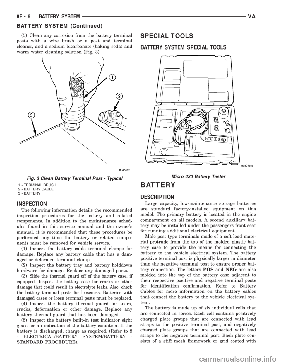
(5) Clean any corrosion from the battery terminal
posts with a wire brush or a post and terminal
cleaner, and a sodium bicarbonate (baking soda) and
warm water cleaning solution (Fig. 3).
INSPECTION
The following information details the recommended
inspection procedures for the battery and related
components. In addition to the maintenance sched-
ules found in this service manual and the owner's
manual, it is recommended that these procedures be
performed any time the battery or related compo-
nents must be removed for vehicle service.
(1) Inspect the battery cable terminal clamps for
damage. Replace any battery cable that has a dam-
aged or deformed terminal clamp.
(2) Inspect the battery tray and battery holddown
hardware for damage. Replace any damaged parts.
(3)
Slide the thermal guard off of the battery case, if
equipped. Inspect the battery case for cracks or other
damage that could result in electrolyte leaks. Also, check
the battery terminal posts for looseness. Batteries with
damaged cases or loose terminal posts must be replaced.
(4) Inspect the battery thermal guard for tears,
cracks, deformation or other damage. Replace any
battery thermal guard that has been damaged.
(5) Inspect the battery built-in test indicator sight
glass for an indication of the battery condition. If the
battery is discharged, charge as required. (Refer to 8
- ELECTRICAL/BATTERY SYSTEM/BATTERY -
STANDARD PROCEDURE).
SPECIAL TOOLS
BATTERY SYSTEM SPECIAL TOOLS
BATTERY
DESCRIPTION
Large capacity, low-maintenance storage batteries
are standard factory-installed equipment on this
model. The primary battery is located in the engine
compartment on all models. A second auxiliary bat-
tery may be installed under the passengers front seat
for running additional electrical equipment.
Male post type terminals made of a soft lead mate-
rial protrude from the top of the molded plastic bat-
tery case to provide the means for connecting the
battery to the vehicle electrical system. The battery
positive terminal post is physically larger in diameter
than the negative terminal post to ensure proper bat-
tery connection. The lettersPOSandNEGare also
molded into the top of the battery case adjacent to
their respective positive and negative terminal posts
for identification confirmation. Refer to Battery
Cables for more information on the battery cables
that connect the battery to the vehicle electrical sys-
tem.
The battery is made up of six individual cells that
are connected in series. Each cell contains positively
charged plate groups that are connected with lead
straps to the positive terminal post, and negatively
charged plate groups that are connected with lead
straps to the negative terminal post. Each plate con-
sists of a stiff mesh framework or grid coated with
Fig. 3 Clean Battery Terminal Post - Typical
1 - TERMINAL BRUSH
2 - BATTERY CABLE
3 - BATTERY
Micro 420 Battery Tester
8F - 6 BATTERY SYSTEMVA
BATTERY SYSTEM (Continued)
Page 146 of 1232
GENERATOR
DESCRIPTION
The generator is belt-driven by the engine using a
serpentine-type drive belt. It is serviced only as a
complete assembly. If the generator fails for any rea-
son, the entire assembly must be replaced.
On certain engines, the decoupler pulley may be
replaced separately.
OPERATION
As the energized rotor begins to rotate within the
generator, the spinning magnetic field induces a cur-
rent into the windings of the stator coil. Once the
generator begins producing sufficient current, it also
provides the current needed to energize the rotor.
The stator winding connections deliver the induced
AC current to 3 positive and 3 negative diodes for
rectification. From the diodes, rectified DC current is
delivered to the vehicle electrical system through the
generator battery terminal.
Although the generators appear the same exter-
nally, different generators with different output rat-
ings are used on this vehicle. Be certain that the
replacement generator has the same output rating
and part number as the original unit. Refer to Spec-
ifications and see Generator Ratings for amperage
ratings and part numbers.
Noise emitting from the generator may be caused
by: worn, loose or defective bearings; a loose or defec-
tive drive pulley (decoupler pulley); incorrect, worn,
damaged or misadjusted fan drive belt; loose mount-
ing bolts; a misaligned drive pulley or a defective sta-
tor or diode.
An instrument panel mounted, battery charge indi-
cator lamp is used. When the key is in the on posi-
tion, the lamp will be illuminated. This is done as a
bulb check. If this lamp remains illuminated while
the engine is running, a Diagnostic Trouble Code
(DTC) has been detected for the charging system.
REMOVAL
CAUTION: DISCONNECT NEGATIVE CABLE FROM
BATTERY BEFORE REMOVING BATTERY OUTPUT
WIRE FROM GENERATOR. FAILURE TO DO SO
CAN RESULT IN INJURY.
CAUTION: Never force a belt over a pulley rim
using a screwdriver. The synthetic fiber of the belt
can be damaged.
CAUTION: When installing a serpentine accessory
drive belt, the belt MUST be routed correctly. The
water pump will be rotating in the wrong direction ifthe belt is installed incorrectly, causing the engine
to overheat. Refer to belt routing label in engine
compartment, or refer to Belt Schematics in Cooling
System.
(1) Disconnect and isolate negative battery cable.
(2) Remove generator drive belt. Refer to Cooling
System for procedure.
(3) Raise and support vehicle.
(4) Remove protective plastic cover from B+ stud
at top of generator.
(5) Remove nut securing battery output cable to
B+ terminal at top of generator.
(6) Unplug field terminal connector at rear of gen-
erator.
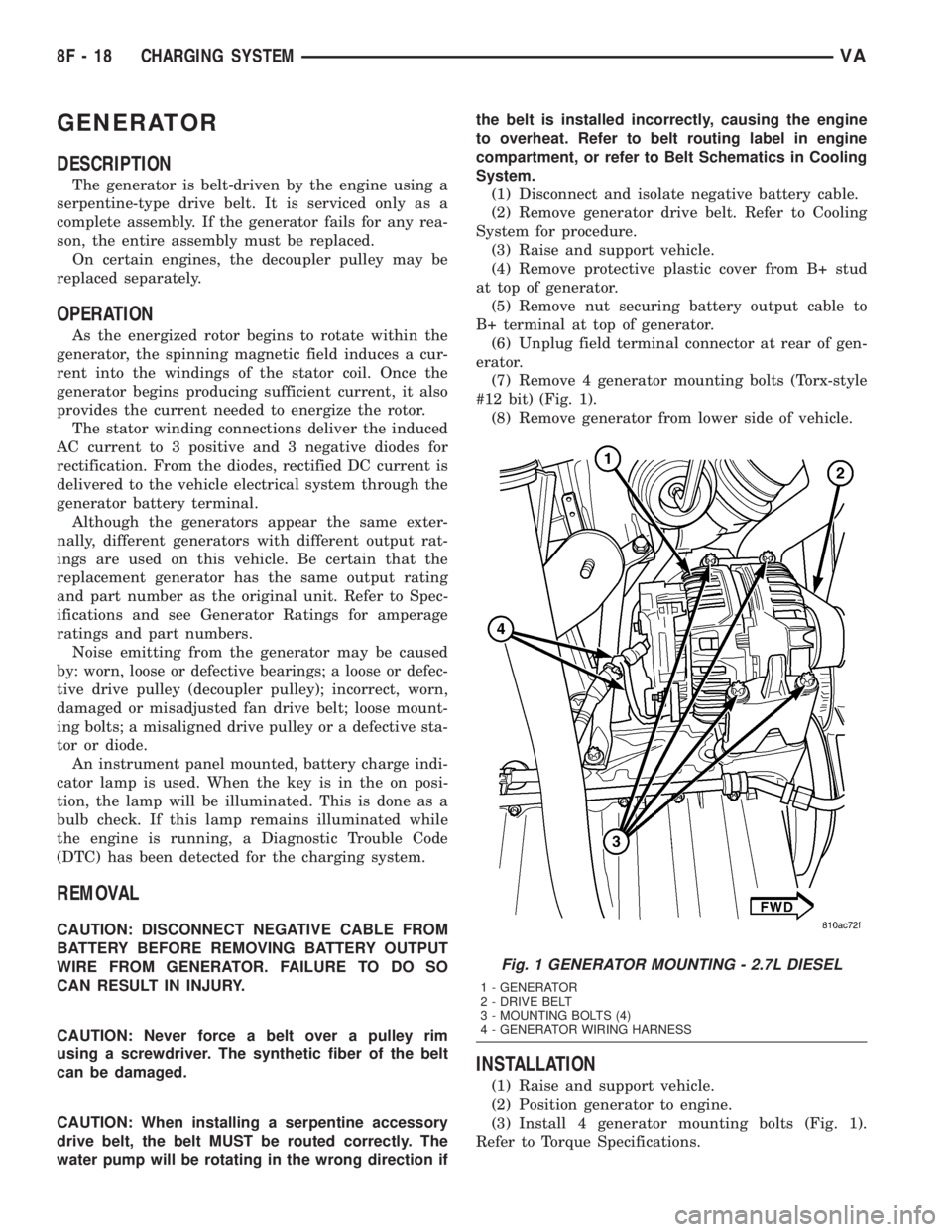
(7) Remove 4 generator mounting bolts (Torx-style
#12 bit) (Fig. 1).
(8) Remove generator from lower side of vehicle.
INSTALLATION
(1) Raise and support vehicle.
(2) Position generator to engine.
(3) Install 4 generator mounting bolts (Fig. 1).
Refer to Torque Specifications.
Fig. 1 GENERATOR MOUNTING - 2.7L DIESEL
1 - GENERATOR
2 - DRIVE BELT
3 - MOUNTING BOLTS (4)
4 - GENERATOR WIRING HARNESS
8F - 18 CHARGING SYSTEMVA
Page 147 of 1232
(4) Connect field terminal connector at rear of gen-
erator.
(5) Install battery output cable and nut to B+ ter-
minal at top of generator. Refer to Torque Specifica-
tions.
(6) Install protective plastic cover to B+ stud at
top of generator.
(7) Lower vehicle.
CAUTION: Never force a belt over a pulley rim
using a screwdriver. The synthetic fiber of the belt
can be damaged.
CAUTION: When installing a serpentine accessory
drive belt, the belt MUST be routed correctly. The
water pump will be rotating in the wrong direction if
the belt is installed incorrectly, causing the engine
to overheat. Refer to belt routing label in engine
compartment, or refer to Belt Schematics in Cooling
System.
(8) Install generator drive belt. Refer to Cooling
System for procedure.
(9) Connect negative battery cable.
(10) Check charging system for proper operation.
GENERATOR DECOUPLER
PULLEY
DESCRIPTION
The generator decoupler is used only with
certain engines.The decoupler is used in place of
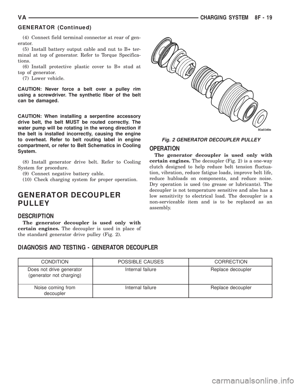
the standard generator drive pulley (Fig. 2).
OPERATION
The generator decoupler is used only with
certain engines.The decoupler (Fig. 2) is a one-way
clutch designed to help reduce belt tension fluctua-
tion, vibration, reduce fatigue loads, improve belt life,
reduce hubloads on components, and reduce noise.
Dry operation is used (no grease or lubricants). The
decoupler is not temperature sensitive and also has a
low sensitivity to electrical load. The decoupler is a
non-serviceable item and is to be replaced as an
assembly.
DIAGNOSIS AND TESTING - GENERATOR DECOUPLER
CONDITION POSSIBLE CAUSES CORRECTION
Does not drive generator
(generator not charging)Internal failure Replace decoupler
Noise coming from
decouplerInternal failure Replace decoupler
Fig. 2 GENERATOR DECOUPLER PULLEY
VACHARGING SYSTEM 8F - 19
GENERATOR (Continued)
Page 158 of 1232
STARTER SOLENOID
This test can only be performed with starter motor
removed from vehicle.
(1) Remove starter motor from vehicle. Refer to
Starter Motor Removal and Installation.
(2)
Disconnect wire from solenoid field coil terminal.
(3)Check for continuity between solenoid terminal
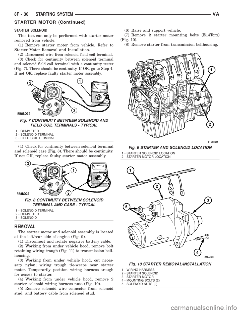
and solenoid field coil terminal with a continuity tester
(Fig. 7). There should be continuity. If OK, go to Step 4.
If not OK, replace faulty starter motor assembly.
(4) Check for continuity between solenoid terminal
and solenoid case (Fig. 8). There should be continuity.
If not OK, replace faulty starter motor assembly.
REMOVAL
The starter motor and solenoid assembly is located
at the left/rear side of engine (Fig. 9).
(1) Disconnect and isolate negative battery cable.
(2) Working from under vehicle hood, remove bolt
retaining wiring trough (Fig. 11) to transmission bell-
housing.
(3) Working from under vehicle hood, cut neces-
sary nylon; wiring trough tie-wraps near starter
motor. Temporarily position wiring harness trough
for access to starter.
(4) Working from under vehicle hood, remove 2
starter solenoid wiring harness nuts (Fig. 10).
(5) Remove solenoid wire connector from solenoid
stud, and battery cable from solenoid stud.(6) Raise and support vehicle.
(7) Remove 2 starter mounting bolts (E14Torx)
(Fig. 10).
(8) Remove starter from transmission bellhousing.
Fig. 7 CONTINUITY BETWEEN SOLENOID AND
FIELD COIL TERMINALS - TYPICAL
1 - OHMMETER
2 - SOLENOID TERMINAL
3 - FIELD COIL TERMINAL
Fig. 8 CONTINUITY BETWEEN SOLENOID
TERMINAL AND CASE - TYPICAL
1 - SOLENOID TERMINAL
2 - OHMMETER
3 - SOLENOID
Fig. 9 STARTER AND SOLENOID LOCATION
1 - STARTER SOLENOID LOCATION
2 - STARTER MOTOR LOCATION
Fig. 10 STARTER REMOVAL/INSTALLATION
1 - WIRING HARNESS
2 - STARTER SOLENOID
3 - STARTER MOTOR
4 - MOUNTING BOLTS (2)
5 - SOLENOID NUTS (2)
8F - 30 STARTING SYSTEMVA
STARTER MOTOR (Continued)