2005 MERCEDES-BENZ SPRINTER check engine
[x] Cancel search: check enginePage 782 of 1232
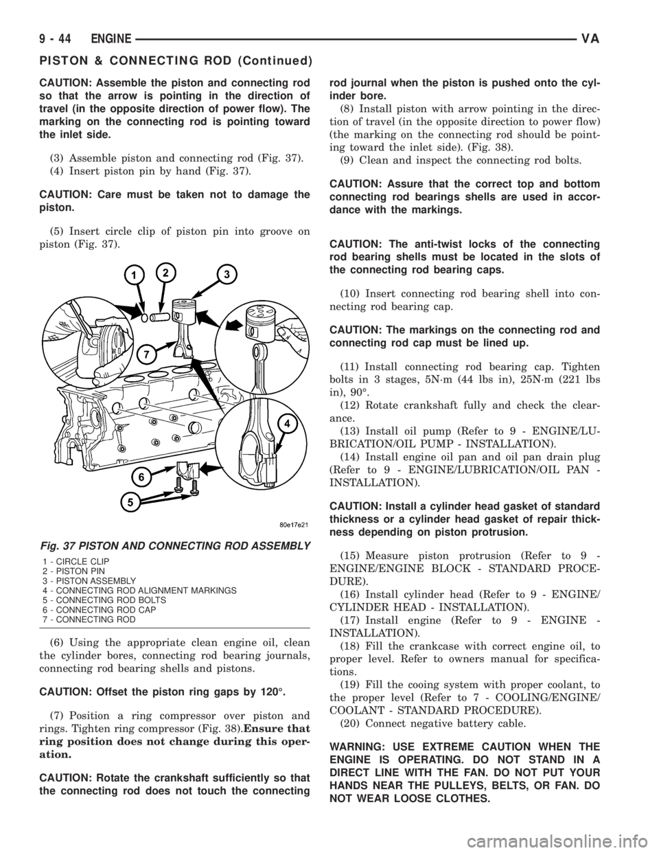
CAUTION: Assemble the piston and connecting rod
so that the arrow is pointing in the direction of
travel (in the opposite direction of power flow). The
marking on the connecting rod is pointing toward
the inlet side.
(3) Assemble piston and connecting rod (Fig. 37).
(4) Insert piston pin by hand (Fig. 37).
CAUTION: Care must be taken not to damage the
piston.
(5) Insert circle clip of piston pin into groove on
piston (Fig. 37).
(6) Using the appropriate clean engine oil, clean
the cylinder bores, connecting rod bearing journals,
connecting rod bearing shells and pistons.
CAUTION: Offset the piston ring gaps by 120É.
(7) Position a ring compressor over piston and
rings. Tighten ring compressor (Fig. 38).Ensure that
ring position does not change during this oper-
ation.
CAUTION: Rotate the crankshaft sufficiently so that
the connecting rod does not touch the connectingrod journal when the piston is pushed onto the cyl-
inder bore.
(8) Install piston with arrow pointing in the direc-
tion of travel (in the opposite direction to power flow)
(the marking on the connecting rod should be point-
ing toward the inlet side). (Fig. 38).
(9) Clean and inspect the connecting rod bolts.
CAUTION: Assure that the correct top and bottom
connecting rod bearings shells are used in accor-
dance with the markings.
CAUTION: The anti-twist locks of the connecting
rod bearing shells must be located in the slots of
the connecting rod bearing caps.
(10) Insert connecting rod bearing shell into con-
necting rod bearing cap.
CAUTION: The markings on the connecting rod and
connecting rod cap must be lined up.
(11) Install connecting rod bearing cap. Tighten
bolts in 3 stages, 5N´m (44 lbs in), 25N´m (221 lbs
in), 90É.
(12) Rotate crankshaft fully and check the clear-
ance.
(13) Install oil pump (Refer to 9 - ENGINE/LU-
BRICATION/OIL PUMP - INSTALLATION).
(14) Install engine oil pan and oil pan drain plug
(Refer to 9 - ENGINE/LUBRICATION/OIL PAN -
INSTALLATION).
CAUTION: Install a cylinder head gasket of standard
thickness or a cylinder head gasket of repair thick-
ness depending on piston protrusion.
(15) Measure piston protrusion (Refer to 9 -
ENGINE/ENGINE BLOCK - STANDARD PROCE-
DURE).
(16) Install cylinder head (Refer to 9 - ENGINE/
CYLINDER HEAD - INSTALLATION).
(17) Install engine (Refer to 9 - ENGINE -
INSTALLATION).
(18) Fill the crankcase with correct engine oil, to
proper level. Refer to owners manual for specifica-
tions.
(19) Fill the cooing system with proper coolant, to
the proper level (Refer to 7 - COOLING/ENGINE/
COOLANT - STANDARD PROCEDURE).
(20) Connect negative battery cable.
WARNING: USE EXTREME CAUTION WHEN THE
ENGINE IS OPERATING. DO NOT STAND IN A
DIRECT LINE WITH THE FAN. DO NOT PUT YOUR
HANDS NEAR THE PULLEYS, BELTS, OR FAN. DO
NOT WEAR LOOSE CLOTHES.
Fig. 37 PISTON AND CONNECTING ROD ASSEMBLY
1 - CIRCLE CLIP
2 - PISTON PIN
3 - PISTON ASSEMBLY
4 - CONNECTING ROD ALIGNMENT MARKINGS
5 - CONNECTING ROD BOLTS
6 - CONNECTING ROD CAP
7 - CONNECTING ROD
9 - 44 ENGINEVA
PISTON & CONNECTING ROD (Continued)
Page 786 of 1232
NOTE: If grooves can be felt in the belt pulley/vibra-
tion damper during inspection, the pulley/damper
must be replaced.
(6) Inspect hub at belt pulley/vibration damper for
wear grooves.
(7) Replace front crankshaft seal.
INSTALLATION
NOTE: Align parallel key, fix in place with grease.
Turn to ensure the slot is aligned with parallel key
in crankshaft.
NOTE: Front crankshaft seal must be replaced
before installing the belt pulley/vibration damper.
(1) Position the belt pulley/vibration damper.
(2) Install crankshaft center bolt and washer.
Tighten bolt in two stages. M8.8 bolt to 200N´m (148
lbs. ft.) then 90É, M10.9 bolt to 325N´m (240 lbs. ft.)
then 90É.
(3) Remove the retaining lock for the crankshaft/
ring gear (Fig. 43).
NOTE: Inspect accessory drive belt for wear.
Replace as necessary.
(4) Install accessory drive belt (Refer to 7 - COOL-
ING/ACCESSORY DRIVE/DRIVE BELTS - INSTAL-
LATION).
(5) Reconnect negative battery cable.
WARNING: USE EXTREME CAUTION WHEN THE
ENGINE IS IN OPERATION. DO NOT STAND IN A
DIRECT LINE WITH THE FAN. DO NOT PUT YOUR
HANDS NEAR THE PULLEYS, BELTS OR FAN. DO
NOT WEAR LOOSE CLOTHING.
(6) Start vehicle and inspect for leaks.
VACUUM PUMP
DESCRIPTION
The vacuum pump is operated by a slotted exten-
sion attached to the vacuum pump shaft. The vac-
uum pump shaft slotted extension fits into, and is
driven by, the exhaust camshaft gear.
The vacuum pump is a constant displacement,
vane-type pump. Vacuum is generated by vanes
mounted in the pump rotor. The rotor is located in
the pump housing and is pressed onto the pump
shaft.
The vacuum pump rotating components are inter-
nally lubricated.The vacuum pump is not serviceable and must be
replaced as a unit. Do not disassemble or attempt to
repair the pump.
OPERATION
Vacuum pump output is transmitted to the Heater,
Electronic, Vacuum, Air Conditioner (HEVAC) and
speed control, systems through a supply hose. The
hose is connected to an outlet port on the pump hous-
ing and uses an in-line check valve to retain system
vacuum when vehicle is not running.
Pump output ranges from a minimum of 8.5 to 25
inches vacuum.
The pump rotor and vanes are rotated by the pump
drive gear. The drive gear is operated by the exhaust
camshaft gear.
REMOVAL
(1) Disconnect negative battery cable.
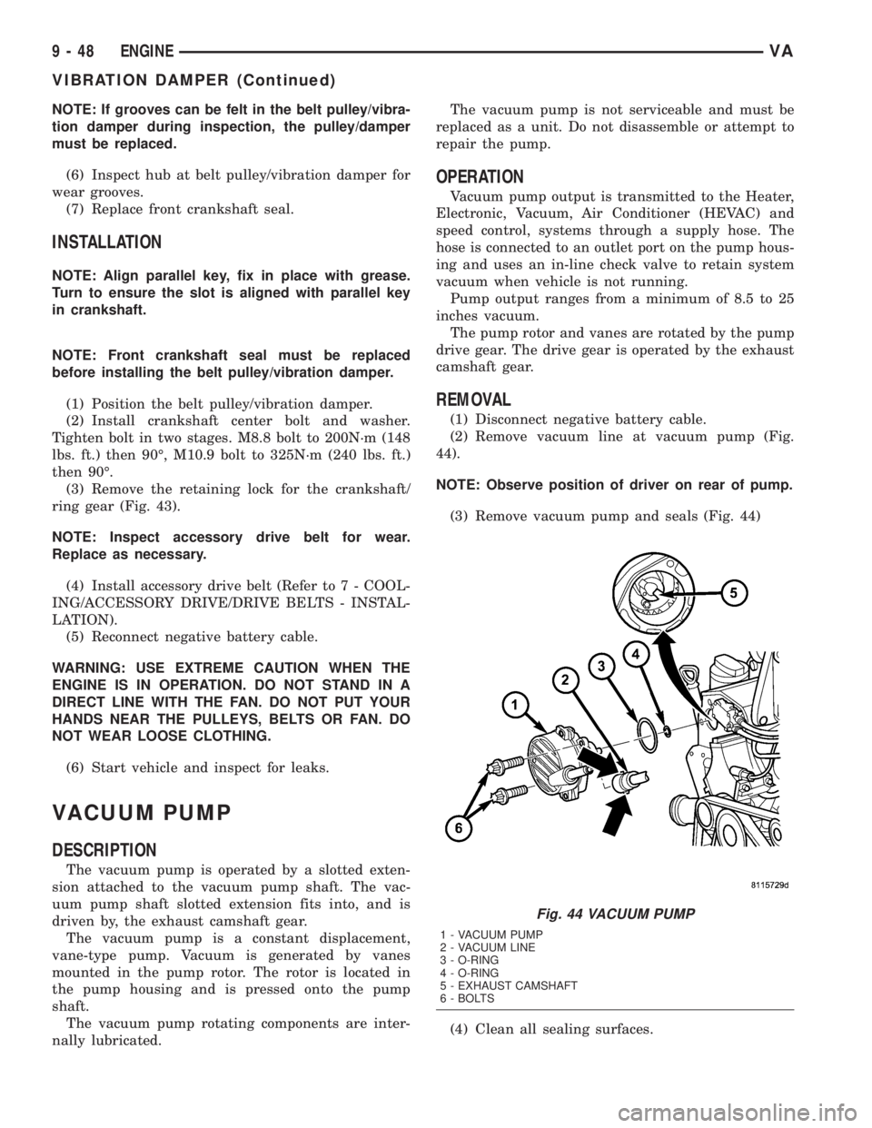
(2) Remove vacuum line at vacuum pump (Fig.
44).
NOTE: Observe position of driver on rear of pump.
(3) Remove vacuum pump and seals (Fig. 44)
(4) Clean all sealing surfaces.
Fig. 44 VACUUM PUMP
1 - VACUUM PUMP
2 - VACUUM LINE
3 - O-RING
4 - O-RING
5 - EXHAUST CAMSHAFT
6 - BOLTS
9 - 48 ENGINEVA
VIBRATION DAMPER (Continued)
Page 788 of 1232
(7) Remove the engine support fixture and adap-
tors.
OIL
REMOVAL - OIL SEPARATOR
(1) Disconnect breather hose.
(2) Remove the separator retaining bolts
(3) Twist to remove oil separator from cover.
INSTALLATION - OIL SEPARATOR
(1) Lubricate the oil separator o - ring with clean
engine oil.
(2) Position separator above cover and apply down-
ward pressure to seat.
(3) Install retaining bolts and tighten to 8N´m (70
lbs. in.).
(4) Connect breather hose.
OIL COOLER & LINES
REMOVAL
WARNING: RISK OF INJURY TO SKIN AND EYES
DUE TO SCALDING FROM HOT COOLANT. DO NOTOPEN THE COOLING SYSTEM UNLESS THE TEM-
PERATURE IS BELOW 194ÉF (90ÉC). WEAR PRO-
TECTIVE CLOTHING AND EYE WEAR. RISK OF
POISONING IF COOLANT IS SWALLOWED. STORE
COOLANT IN PROPER AND APPROPRIATELY
MARKED CONTAINERS.
(1) Drain cooling system.
(2) Remove the oil filter.
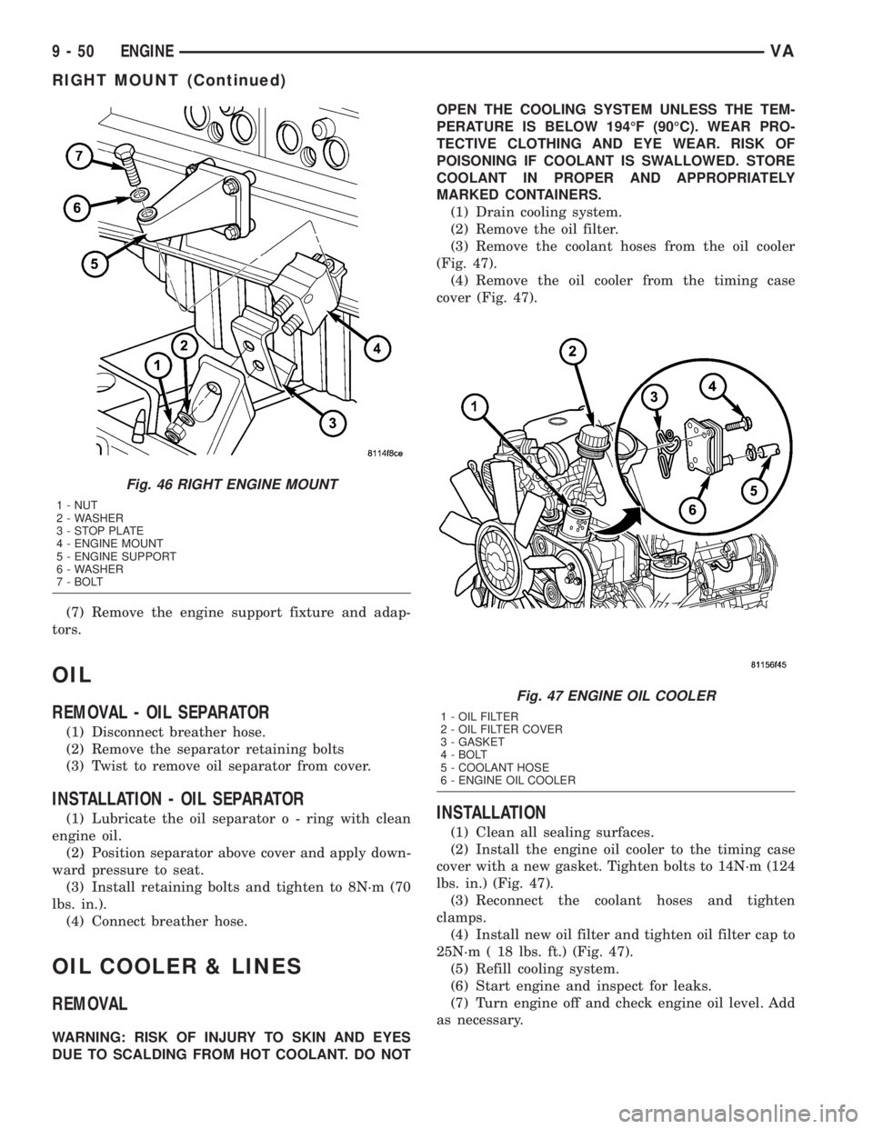
(3) Remove the coolant hoses from the oil cooler
(Fig. 47).
(4) Remove the oil cooler from the timing case
cover (Fig. 47).
INSTALLATION
(1) Clean all sealing surfaces.
(2) Install the engine oil cooler to the timing case
cover with a new gasket. Tighten bolts to 14N´m (124
lbs. in.) (Fig. 47).
(3) Reconnect the coolant hoses and tighten
clamps.
(4) Install new oil filter and tighten oil filter cap to
25N´m ( 18 lbs. ft.) (Fig. 47).
(5) Refill cooling system.
(6) Start engine and inspect for leaks.
(7) Turn engine off and check engine oil level. Add
as necessary.
Fig. 46 RIGHT ENGINE MOUNT
1 - NUT
2 - WASHER
3 - STOP PLATE
4 - ENGINE MOUNT
5 - ENGINE SUPPORT
6 - WASHER
7 - BOLT
Fig. 47 ENGINE OIL COOLER
1 - OIL FILTER
2 - OIL FILTER COVER
3 - GASKET
4 - BOLT
5 - COOLANT HOSE
6 - ENGINE OIL COOLER
9 - 50 ENGINEVA
RIGHT MOUNT (Continued)
Page 813 of 1232
CATALYTIC CONVERTER
REMOVAL
(1) Raise and support the vehicle.
(2) Saturate the clamp nuts with heat valve lubri-
cant. Allow 5 minutes for penetration. Remove the
rear clamp. (Fig. 1)
(3) Saturate the clamp nuts with heat valve lubri-
cant. Allow 5 minutes for penetration. Remove the
front clamp.
(4) Remove the cataylic converter and muffler
assembly from the isolators.
(5) Seperat the cataylic converter and muffler
assembly from the tailpipe and the exhaust pipe.
(6) Remove the cataylic converter and muffler
assembly and isolators from the vehicle.
(7) Remove the bolt, nut and front isolator from
the cataylic converter and muffler assembly.
(8) Remove the rear isolator from the cataylic con-
verter and muffler assembly.
(9)
INSTALLATION
(1) Install bolt, front isolator and nut (Fig. 1).
(2) Install rear insulator onto the cataylic con-
verter and muffler assembly
(3) Position the cataylic conveter and muffler
assembly into the exhaust pipe and tailpipe until
alignment tab is inserted into the alignment slot.
(4) Install the front and rear insulators.
(5) Install the real clamp.
(6) Install the front clamp.
(7) Lower vehicle.
(8) Start the vehicle and inspect for exhaust leaks.
Repair exhaust leaks as necessary.
(9) Check the exhaust system for contact with the
body panels. Make necessary adjustments, if neces-
sary.
EXHAUST PIPE
REMOVAL
(1) Raise and support the vehicle.
(2) Saturate the clamp nuts with heat valve lubri-
cant. Allow 5 minutes for penetration. Remove the
front and rear clamp (Fig. 1).
(3) Remove the mounting bracket nuts.
(4) Remove the exhaust pipe.
INSTALLATION
(1) Position the exhaust pipe into the exhaust pipe
into the cataylic converter and muffler assembly
until alignment tab is inserted into the alignment
slot.
(2) Install mounting bracket and nuts (Fig. 1).(3) Install clamp.
(4) Lower the vehicle.
(5) Start the vehicle and inspect for exhaust leaks.
Repair exhaust leaks as necessary.
(6) Check the exhaust system for contact with the
body panels. Make necessary adjustments, if neces-
sary.
TAILPIPE
REMOVAL
(1) Raise and support the vehicle.
(2) Saturate the clamp nuts with heat valve lubri-
cant. Allow 5 minutes for penetration (Fig. 1).
(3) Remove the clamp.
(4) Remove the tailpipe and insulator form the
vehicle
(5) Remove the insulator from the tailpipe.
INSTALLATION
(1) Position the tail pipe into the cataylic converter
and muffler assembly until alignment tab is inserted
into the alignment slot.
(2) Install the insulator.
(3) Install the clamp.
(4) Lower the vehicle.
(5) Start the vehicle and inspect for exhaust leaks.
Repair exhaust leaks as necessary.
(6) Check the exhaust system for contact with the
body panels. Make necessary adjustments, if neces-
sary.
TURBOCHARGER SYSTEM
DESCRIPTION
CAUTION: The turbocharger is a performance part
and must not be tampered with. The boost pressure
bracket is an integral part of the turbocharger. Tam-
pering with the boost pressure components can
reduce durability by increasing cylinder pressure
and thermal loading due to incorrect inlet and
exhaust manifold pressure. Poor fuel economy and
failure to meet regulatory emissions laws may
result. Increasing the turbocharger boost WILL NOT
increase engine power.
The turbocharger used on this vehicle is of the
variable turbine type. These turbochargers use the
entire exhaust energy to boost efficiency of the turbo-
charger and the engine.
The advantages of a turbocharger with variable
turbine geometry are:
²Higher charge pressure already in the lower and
in upper engine speed ranges.
VAEXHAUST SYSTEM 11 - 3
Page 815 of 1232
Low turbocharger boost pressure and low engine
performance can be caused by leaks in the charge air
cooler or it's plumbing. The following procedure out-
lines how to check for leaks in the charge air cooler
system.
(1) Loosen clamp and remove turbocharger to air
inlet duct rubber sleeve from turbocharger.
(2) Insert Special Tool 8442 Adapter into the rub-
ber sleeve. Tighten existing clamp to 8 N´m (72
in.lbs.).
CAUTION: Do not apply more than 138 kpa (20 psi)
air pressure to the charge air cooler system, sever
damage to the charge air cooler system may occur.
(3) Connect regulated air supply to air fitting on
Special Tool 8442 Adapter. Set air pressure to a Max-
imum of 138 kpa (20 psi).
(4) Using soapy water check the air inlet ducts,
rubber sleeves, charge air cooler and intake manifold
for leaks.
REMOVAL
(1) Remove front bumper.
(2) Remove headlamp assemblies.
(3) Remove front cross member together with front
grille.
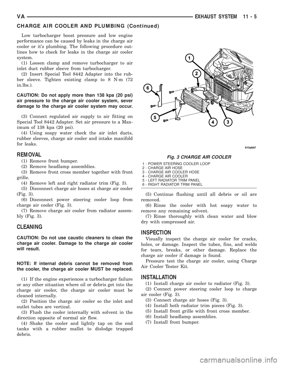
(4) Remove left and right radiator trim (Fig. 3).
(5) Disconnect charge air hoses at charge air cooler
(Fig. 3).
(6) Disconnect power steering cooler loop from
charge air cooler (Fig. 3).
(7) Remove charge air cooler from radiator assem-
bly (Fig. 3).
CLEANING
CAUTION: Do not use caustic cleaners to clean the
charge air cooler. Damage to the charge air cooler
will result.
NOTE: If internal debris cannot be removed from
the cooler, the charge air cooler MUST be replaced.
(1) If the engine experiences a turbocharger failure
or any other situation where oil or debris get into the
charge air cooler, the charge air cooler must be
cleaned internally.
(2) Position the charge air cooler so the inlet and
outlet tubes are vertical.
(3) Flush the cooler internally with solvent in the
direction opposite of normal air flow.
(4) Shake the cooler and lightly tap on the end
tanks with a rubber mallet to dislodge trapped
debris.(5) Continue flushing until all debris or oil are
removed.
(6) Rinse the cooler with hot soapy water to
remove any remaining solvent.
(7) Rinse thoroughly with clean water and blow
dry with compressed air.
INSPECTION
Visually inspect the charge air cooler for cracks,
holes, or damage. Inspect the tubes, fins, and welds
for tears, breaks, or other damage. Replace the
charge air cooler if damage is found.
Pressure test the charge air cooler, using Charge
Air Cooler Tester Kit.
INSTALLATION
(1) Install charge air cooler to radiator (Fig. 3).
(2) Connect power steering cooler loop to charge
air cooler (Fig. 3).
(3) Connect charge air hoses (Fig. 3).
(4) Install both radiator trim pieces (Fig. 3).
(5) Install front grille with front cross member.
(6) Install headlamp assemblies.
(7) Install front bumper.
Fig. 3 CHARGE AIR COOLER
1 - POWER STEERING COOLER LOOP
2 - CHARGE AIR HOSE
3 - CHARGE AIR COOLER HOSE
4 - CHARGE AIR COOLER
5 - LEFT RADIATOR TRIM PANEL
6 - RIGHT RADIATOR TRIM PANEL
VAEXHAUST SYSTEM 11 - 5
CHARGE AIR COOLER AND PLUMBING (Continued)
Page 816 of 1232
TURBOCHARGER
DESCRIPTION
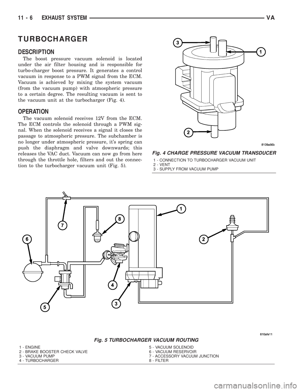
The boost pressure vacuum solenoid is located
under the air filter housing and is responsible for
turbo-charger boost pressure. It generates a control
vacuum in response to a PWM signal from the ECM.
Vacuum is achieved by mixing the system vacuum
(from the vacuum pump) with atmospheric pressure
to a certain degree. The resulting vacuum is sent to
the vacuum unit at the turbocharger (Fig. 4).
OPERATION
The vacuum solenoid receives 12V from the ECM.
The ECM controls the solenoid through a PWM sig-
nal. When the solenoid receives a signal it closes the
passage to atmospheric pressure. The subchamber is
no longer under atmospheric pressure, it's spring can
push the diaphragm and valve downwards; this
releases the VAC duct. Vacuum can now go from here
through the throttle hole, filters and out the connec-
tion to the turbocharger vacuum unit (Fig. 5).
Fig. 4 CHARGE PRESSURE VACUUM TRANSDUCER
1 - CONNECTION TO TURBOCHARGER VACUUM UNIT
2 - VENT
3 - SUPPLY FROM VACUUM PUMP
Fig. 5 TURBOCHARGER VACUUM ROUTING
1 - ENGINE 5 - VACUUM SOLENOID
2 - BRAKE BOOSTER CHECK VALVE 6 - VACUUM RESERVOIR
3 - VACUUM PUMP 7 - ACCESSORY VACUUM JUNCTION
4 - TURBOCHARGER 8 - FILTER
11 - 6 EXHAUST SYSTEMVA
Page 827 of 1232
(3) Tighten steering gear bolts in three stages as
follows.
1. Tighten to 25 N´m (18 ft. lbs.)
2. Then tighten to 45 N´m (33 ft. lbs.)
3. Then tighten bolts an additional 90É.
(4) Install stabilizer bar. (Refer to 2 - SUSPEN-
SION/FRONT/STABILIZER BAR - INSTALLATION)
(5) Install heat shield and nuts.
(6) Install jounce bumpers and install nuts.
(7) Install support clips and brake lines.
(8) Raise engine cradle into place and install bolts.
(9) Tighten bolts to 125 N´m (92 ft. lbs.).
(10) Connect brake lines at couplings and tighten
to 14 N´m (10 ft. lbs.).
(11) Position power steering hose and install sup-
port bracket bolt.
(12) Install both power steering hoses at steering
gear. (Refer to 19 - STEERING/PUMP/HOSES -
INSTALLATION)
(13) Connect steering shaft to gear and install the
lower pinch bolt.
(14) Tighten lower pinch bolt to 24 N´m (18 ft.
lbs.).
(15) Install new tie straps holding transmission
harness to cradle.
(16) Install front spring. (Refer to 2 - SUSPEN-
SION/FRONT/SPRING - INSTALLATION)
(17) Install engine mount nuts and tighten to 45
N´m (33 ft. lbs.).
(18) Install calipers. (Refer to 5 - BRAKES/HY-
DRAULIC/MECHANICAL/DISC BRAKE CALIPERS
- INSTALLATION)
(19) Install new tie straps holding wheel speed
sensors and brake pad wear sensors wire harness to
cradle.
(20) Check and align vehicle to specifications.
(Refer to 2 - SUSPENSION/WHEEL ALIGNMENT -
STANDARD PROCEDURE)
REAR CROSSMEMBER -
TRANSMISSION
REMOVAL
(1) Raise and support the vehicle. (Refer to
LUBRICATION & MAINTENANCE/HOISTING -
STANDARD PROCEDURE)
(2) Support transmission with a suitable lifting
device.
(3) Remove the bolts/nuts and remove transmis-
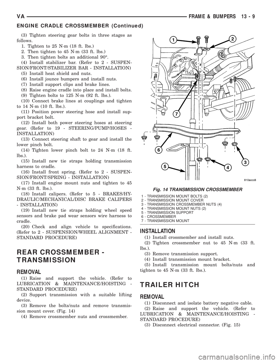
sion mount cover. (Fig. 14)
(4) Remove crossmember nuts and crossmember.
INSTALLATION
(1) Install crossmember and install nuts.
(2) Tighten crossmember nut to 45 N´m (33 ft.
lbs.).
(3) Remove transmission support.
(4) Install transmission mount bracket.
(5) Install transmission mount bolts/nuts and
tighten to 45 N´m (33 ft. lbs.).
TRAILER HITCH
REMOVAL
(1) Disconnect and isolate battery negative cable.
(2) Raise and support the vehicle. (Refer to
LUBRICATION & MAINTENANCE/HOISTING -
STANDARD PROCEDURE)
(3) Disconnect electrical connector. (Fig. 15)
Fig. 14 TRANSMISSION CROSSMEMBER
1 - TRANSMISSION MOUNT BOLTS (2)
2 - TRANSMISSION MOUNT COVER
3 - TRANSMISSION CROSSMEMBER NUTS (4)
4 - TRANSMISSION MOUNT NUTS (2)
5 - TRANSMISSION SUPPORT
6 - CROSSMEMBER
7 - TRANSMISSION MOUNT
VAFRAME & BUMPERS 13 - 9
ENGINE CRADLE CROSSMEMBER (Continued)
Page 829 of 1232
FUEL SYSTEM
TABLE OF CONTENTS
page page
FUEL SYSTEM
WARNING
WARNING - HIGH FUEL SYSTEM
PRESSURE...........................1
WARNING............................1
DIAGNOSIS AND TESTING
DIAGNOSIS AND TESTING - HIGH
PRESSURE FUEL LINES.................1
DIAGNOSIS AND TESTING - AIR IN FUEL
SYSTEM.............................2
STANDARD PROCEDURE
STANDARD PROCEDURES - CLEANING
FUEL SYSTEM COMPONENTS............2STANDARD PROCEDURE -
DISCONNECTING AND CONNECTING
FUEL LINES..........................2
STANDARD PROCEDURES - DRAINING
WATER FROM FUEL FILTER..............2
STANDARD PROCEDURE - LOW
PRESSURE FUEL PUMP TEST............3
FUEL DELIVERY..........................4
FUEL INJECTION........................17
FUEL SYSTEM
WARNING
WARNING - HIGH FUEL SYSTEM PRESSURE
WARNING: HIGH-PRESSURE FUEL LINES DELIVER
FUEL UNDER EXTREME PRESSURE FROM THE
INJECTION PUMP TO THE INJECTORS. THIS
MAYBE AS HIGH AS 1600BAR (23,200PSI). USE
EXTREME CAUTION WHEN INSPECTING FOR HIGH-
PRESSURE FUEL LEAKS. FUEL UNDER THIS
AMOUNT OF PRESSURE CAN PENETRATE SKIN
CAUSING PERSONAL INJURY OR DEATH. INSPECT
HIGH-PRESSURE FUEL LEAKS WITH A SHEET OF
CARDBOARD. WEAR SAFETY GOGGLES AND ADE-
QUATE PROTECTIVE CLOTHING WHEN SERVICING
FUEL SYSTEM.
WARNING
WARNING: UNDER NO CIRCUMSTANCES SHOULD
GASOLINE BE MIXED WITH DIESEL FUEL (NOT
EVEN DURING WINTER). THE HIGH PRESSURE
PUMP IS LUBRICATED BY DIESEL FUEL. IMMEDI-
ATE FUEL SYSTEM DAMAGE MAY OCCUR CAUS-
ING REPLACEMENT AND FLUSHING OF THE
COMPLETE DIESEL FUEL SYSTEM. HIGH PRES-
SURE PUMP SEIZURE WILL CAUSE METAL PARTI-
CLES TO SPREAD THROUGH OUT THE FUEL
CIRCUIT. ALL CDI FUEL SYSTEM COMPONENTS
CONNECTED TO THE FUEL CIRCUIT WILL HAVE TO
BE EXCHANGED AND THE LINES FLUSHED.
DIAGNOSIS AND TESTING
DIAGNOSIS AND TESTING - HIGH PRESSURE
FUEL LINES
(Refer to 14 - FUEL SYSTEM - WARNING). High-
pressure fuel line leaks can cause starting problems
and poor engine performance.
WARNING: DUE TO EXTREME FUEL PRESSURES,
USE EXTREME CAUTION WHEN INSPECTING FOR
HIGH-PRESSURE FUEL LEAKS. DO NOT GET YOUR
HAND NEAR A SUSPECTED LEAK. INSPECT FOR
HIGH-PRESSURE FUEL LEAKS WITH A SHEET OF
CARDBOARD. HIGH FUEL INJECTION PRESSURE
CAN CAUSE PERSONAL INJURY IF CONTACT IS
MADE WITH THE SKIN.
Start the engine. Move the cardboard over the
high-pressure fuel lines and check for fuel spray onto
the cardboard (Fig. 1). If a high-pressure line connec-
tion is leaking, tighten the connection and perform
the Fuel System Air Purge procedure (Refer to 14 -
FUEL SYSTEM - STANDARD PROCEDURE).
Replace damaged, restricted or leaking high-pressure
fuel lines with the correct replacement line.
CAUTION: The high-pressure fuel lines cannot con-
tact each other or other components. Do not
attempt to weld high-pressure fuel lines or to repair
lines that are damaged. Only use the recommended
lines when replacement of high-pressure fuel line is
necessary.
VAFUEL SYSTEM 14 - 1