2005 MERCEDES-BENZ SPRINTER transmission fluid
[x] Cancel search: transmission fluidPage 872 of 1232
PUMP
TABLE OF CONTENTS
page page
PUMP
DESCRIPTION.........................12
OPERATION...........................12
DIAGNOSIS AND TESTING - PUMP LEAKAGE . 12
STANDARD PROCEDURE
STANDARD PROCEDURE - POWER
STEERING PUMP - INITIAL OPERATION....12
STANDARD PROCEDURE - FLUSHING
POWER STEERING SYSTEM............13
REMOVAL.............................13
INSTALLATION.........................13
SPECIFICATIONS - TORQUE CHART........14
FLUID
STANDARD PROCEDURE
POWER STEERING PUMP FILL AND BLEED
PROCEDURE........................14FLUID COOLER TUBE
REMOVAL.............................14
INSTALLATION.........................14
HOSES
REMOVAL
REMOVAL - PRESSURE HOSE...........15
REMOVAL - RETURN LINE FROM PUMP TO
COOLER TUBE.......................15
REMOVAL - RETURN HOSE FROM GEAR
TO COOLER TUBE....................15
INSTALLATION
INSTALLATION - PRESSURE HOSE.......15
INSTALLATION - RETURN LINE FROM
PUMP TO COOLER TUBE...............15
INSTALLATION - RETURN HOSE FROM
GEAR TO COOLER TUBE...............15
PUMP
DESCRIPTION
CAUTION: Mopar ATF+4 Automatic Transmission
fluid or equivalent is to be used in the power steer-
ing system. No other power steering or automatic
transmission fluid is to be used in the system.
Damage may result to the power steering pump and
system if any other fluid is used, and do not over-
fill.
The pump is connected to the steering gear via the
pressure hose and the return hose. The pump shaft
has a pressed-on pulley that is belt driven by the
crankshaft pulley.
All vehicles are equipped with a power steering
fluid cooler.
NOTE: Power steering pumps are not interchange-
able with pumps installed on other vehicles.
OPERATION
Hydraulic pressure is provided for the power steer-
ing gear by the belt driven power steering pump. The
power steering pumps are constant flow rate and dis-
placement, vane-type pumps.
DIAGNOSIS AND TESTING - PUMP LEAKAGE
The pump is serviced as an assembly and should
not be disassembled. The plastic pump reservoir and
the reservoir o-rings can be replaced.
Check for leaks in the following areas:
²Pump shaft seal behind the pulley
²Pump to reservoir O-ring
²Reservoir cap
²Pressure and return lines
²Flow control valve fitting
STANDARD PROCEDURE
STANDARD PROCEDURE - POWER STEERING
PUMP - INITIAL OPERATION
WARNING: THE FLUID LEVEL SHOULD BE
CHECKED WITH ENGINE OFF TO PREVENT INJURY
FROM MOVING COMPONENTS.
CAUTION: Mopar ATF+4 Automatic Transmission
fluid or equivalent is to be used in the power steer-
ing system. No other power steering or automatic
transmission fluid is to be used in the system.
Damage may result to the power steering pump and
system if any other fluid is used, and do not over-
fill.
19 - 12 PUMPVA
Page 874 of 1232
SPECIFICATIONS - TORQUE CHART
TORQUE SPECIFICATIONS
DESCRIPTION N´m Ft. Lbs. In. Lbs.
Power Steering Pump To
Timing Case Cover/
Support21 15 185
High Pressure Flexible
Hose To Power Steering
Pump38 28 336
Power Steering Pulley To
Pump30 22 265
FLUID
STANDARD PROCEDURE
POWER STEERING PUMP FILL AND BLEED
PROCEDURE
(1) Remove the cap from the fluid reservoir.
Check cap seal for damage and replace if
needed.
(2) Fill the power steering pump with Mopar
ATF+4 Automatic Transmission fluid or equivalent.
Do not fill fluid beyond the MAX mark.
(3) Raise the vehicles front wheels off the ground.
(4) With the engine off turn the steering wheel
from right to left.Perform this step until all the
bubble formations can no longer be seen in the
power steering reservoir.
(5) Start the engine and turn the steering wheel
with the engine at idle speed then shut the engine off
and check for correct oil level and no bubble in the
system.
(6) Reinstall power steering cap tightly.
(7) Test the system for leaks and proper operation.
FLUID COOLER TUBE
REMOVAL
(1) Siphon as much power steering fluid as possi-
ble out of the reservoir.
(2) Remove the grille (Refer to 23 - BODY/EXTE-
RIOR/GRILLE - REMOVAL).
(3) Remove the left headlight assembly.
(4) Disconnect the return lines from the cooler
tube.
(5) Remove the radiator clips (2).
(6) Remove the heat shield bolt for the turbo at
the core support.
(7) Remove the right headlight assembly.(8) Remove the core support bolts (4) and discon-
nect the hood latch cable.
(9) Remove the fan bracket bolts (4) to the radiator
(Fig. 2).
(10) Remove the two upper screws for the con-
denser (Fig. 2).
(11) Remove the condenser air dam shield.
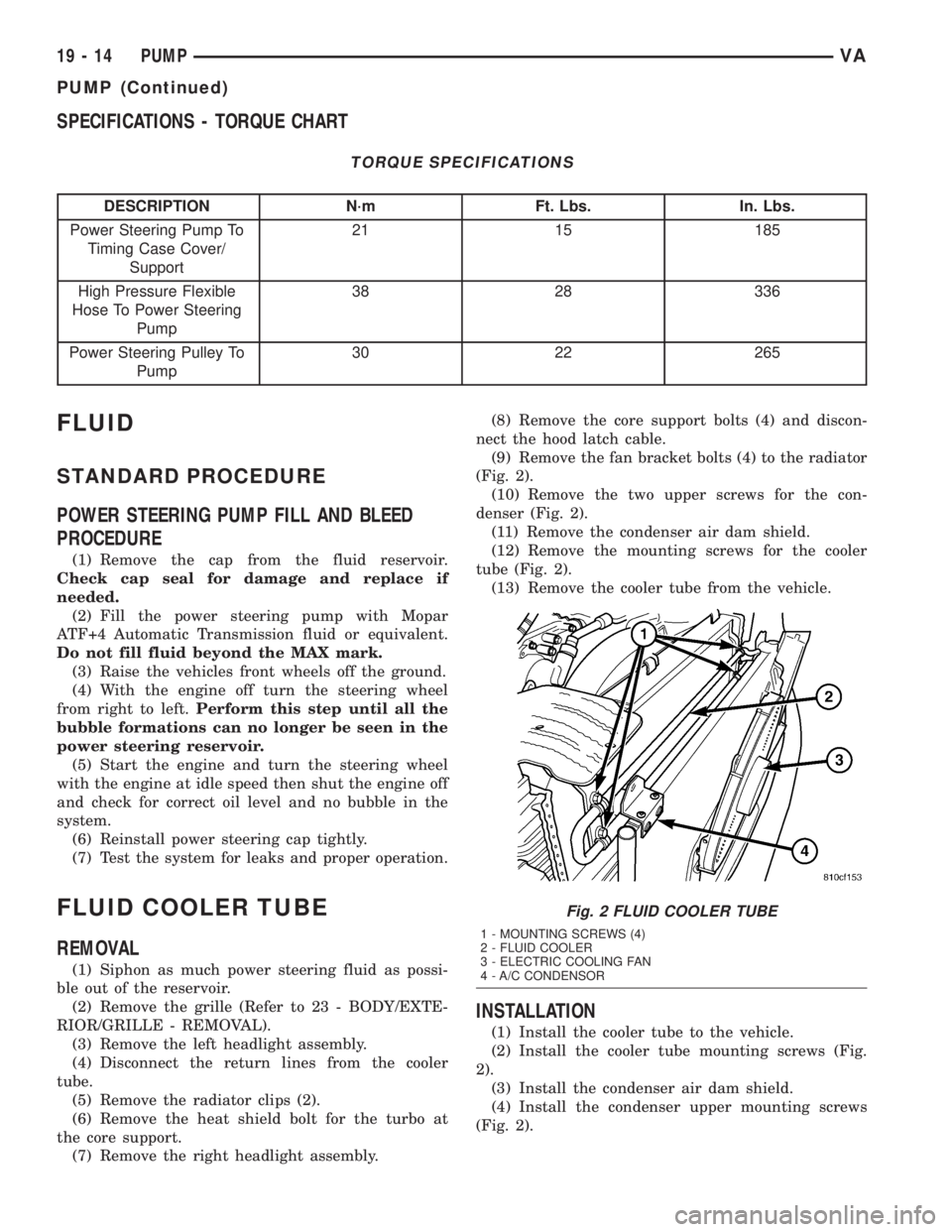
(12) Remove the mounting screws for the cooler
tube (Fig. 2).
(13) Remove the cooler tube from the vehicle.
INSTALLATION
(1) Install the cooler tube to the vehicle.
(2) Install the cooler tube mounting screws (Fig.
2).
(3) Install the condenser air dam shield.
(4) Install the condenser upper mounting screws
(Fig. 2).
Fig. 2 FLUID COOLER TUBE
1 - MOUNTING SCREWS (4)
2 - FLUID COOLER
3 - ELECTRIC COOLING FAN
4 - A/C CONDENSOR
19 - 14 PUMPVA
PUMP (Continued)
Page 877 of 1232
TRANSMISSION
AUTOMATIC TRANSMISSION - NAG1
TABLE OF CONTENTS
page page
AUTOMATIC TRANSMISSION - NAG1
DESCRIPTION..........................2
OPERATION............................4
DIAGNOSIS AND TESTING
DIAGNOSIS AND TESTING - AUTOMATIC
TRANSMISSION......................23
DIAGNOSIS AND TESTING - PRELIMINARY . 23
DIAGNOSIS AND TESTING - ROAD
TESTING............................23
DIAGNOSIS AND TESTING - AUTOMATIC
TRANSMISSION......................24
STANDARD PROCEDURE - ALUMINUM
THREAD REPAIR......................27
REMOVAL.............................27
DISASSEMBLY.........................30
ASSEMBLY............................34
INSTALLATION.........................41
SCHEMATICS AND DIAGRAMS............47
SPECIFICATIONS - NAG1 AUTOMATIC
TRANSMISSION......................68
SPECIAL TOOLS - NAG1 AUTOMATIC
TRANSMISSION......................69
DRIVING CLUTCHES
DESCRIPTION.........................72
OPERATION...........................72
DRIVING CLUTCH K1
DISASSEMBLY.........................74
ASSEMBLY............................75
DRIVING CLUTCH K2
DISASSEMBLY.........................76
ASSEMBLY............................78
DRIVING CLUTCH K3
DISASSEMBLY.........................80
ASSEMBLY............................80
ELECTROHYDRAULIC UNIT
DESCRIPTION.........................82
OPERATION...........................87
REMOVAL.............................92
DISASSEMBLY.........................92
ASSEMBLY............................95
INSTALLATION........................100
FLUID AND FILTER
DESCRIPTION........................101
OPERATION..........................101DIAGNOSIS AND TESTING
DIAGNOSIS AND TESTING - EFFECTS OF
INCORRECT FLUID LEVEL.............102
DIAGNOSIS AND TESTING - CAUSES OF
BURNT FLUID.......................102
DIAGNOSIS AND TESTING - FLUID
CONTAMINATION....................102
STANDARD PROCEDURE
STANDARD PROCEDURE - CHECK OIL
LEVEL.............................102
STANDARD PROCEDURE - TRANSMISSION
FILL...............................103
STANDARD PROCEDURE - FLUID/FILTER
SERVICE...........................104
FREEWHEELING CLUTCH
DESCRIPTION........................105
OPERATION..........................105
DISASSEMBLY........................106
ASSEMBLY...........................107
GEARSHIFT CABLE
DIAGNOSIS AND TESTING - GEARSHIFT
CABLE.............................109
REMOVAL............................109
INSTALLATION........................109
HOLDING CLUTCHES
DESCRIPTION........................111
OPERATION..........................112
HOLDING CLUTCH B1
DISASSEMBLY........................112
ASSEMBLY...........................113
HOLDING CLUTCH B2
DISASSEMBLY........................115
ASSEMBLY...........................116
INPUT SPEED SENSORS
DESCRIPTION........................119
OPERATION..........................119
OIL PUMP
DESCRIPTION........................120
OPERATION..........................120
DISASSEMBLY........................120
ASSEMBLY...........................121
OUTPUT SHAFT BEARING
REMOVAL............................122
INSTALLATION........................122
VATRANSMISSION 21 - 1
Page 899 of 1232
DIAGNOSIS AND TESTING
DIAGNOSIS AND TESTING - AUTOMATIC
TRANSMISSION
CAUTION: Before attempting any repair on a NAG1
automatic transmission, check for Diagnostic Trou-
ble Codes with the DRBTscan tool.
Transmission malfunctions may be caused by these
general conditions:
²Poor engine performance.
²Improper adjustments.
²Hydraulic malfunctions.
²Mechanical malfunctions.
²Electronic malfunctions.
²Transfer case performance.
Diagnosis of these problems should always begin
by checking the easily accessible variables: fluid level
and condition, gearshift cable adjustment. Then per-
form a road test to determine if the problem has been
corrected or if more diagnosis is necessary.
DIAGNOSIS AND TESTING - PRELIMINARY
Two basic procedures are required. One procedure
for vehicles that are drivable and an alternate proce-
dure for disabled vehicles (will not back up or move
forward).
VEHICLE IS DRIVABLE
(1) Check for transmission fault codes using DRBt
scan tool.
(2) Check fluid level and condition.
(3) Adjust gearshift cable if complaint was based
on delayed, erratic, or harsh shifts.
(4) Road test and note how transmission upshifts,
downshifts, and engages.
VEHICLE IS DISABLED
(1) Check fluid level and condition.(2) Check for broken or disconnected gearshift
cable.
(3) Check for cracked, leaking cooler lines, or loose
or missing pressure-port plugs.
(4) Raise and support vehicle on safety stands,
start engine, shift transmission into gear, and note
following:
(a) If propeller shaft turns but wheels do not,
problem is with differential or axle shafts.
(b) If propeller shaft does not turn and transmis-
sion is noisy, stop engine. Remove oil pan, and
check for debris. If pan is clear, remove transmis-
sion and check for damaged driveplate, converter,
oil pump, or input shaft.
(c) If propeller shaft does not turn and transmis-
sion is not noisy, perform hydraulic-pressure test to
determine if problem is hydraulic or mechanical.
DIAGNOSIS AND TESTING - ROAD TESTING
Before road testing, be sure the fluid level and con-
trol cable adjustments have been checked and
adjusted if necessary. Verify that all diagnostic trou-
ble codes have been resolved.
Observe engine performance during the road test.
A poorly tuned engine will not allow accurate analy-
sis of transmission operation.
Operate the transmission in all gear ranges. Check
for shift variations and engine flare which indicates
slippage. Note if shifts are harsh, spongy, delayed,
early, or if part throttle downshifts are sensitive.
Slippage indicated by engine flare, usually means
clutch, overrunning clutch, or line pressure problems.
A slipping clutch can often be determined by com-
paring which internal units are applied in the vari-
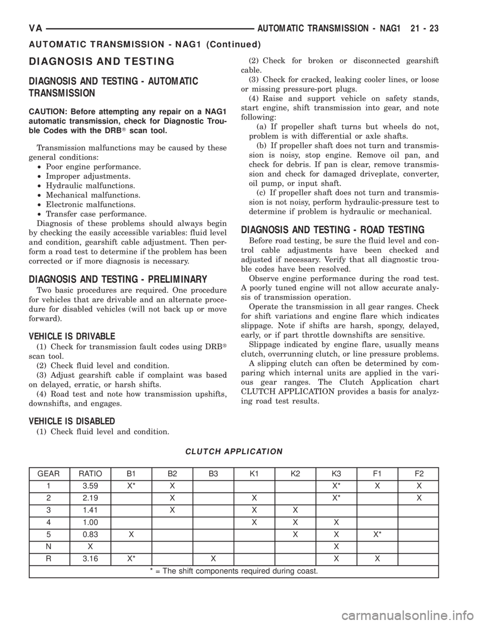
ous gear ranges. The Clutch Application chart
CLUTCH APPLICATION provides a basis for analyz-
ing road test results.
CLUTCH APPLICATION
GEAR RATIO B1 B2 B3 K1 K2 K3 F1 F2
1 3.59 X* X X* X X
2 2.19 X X X* X
3 1.41 X X X
4 1.00 X X X
5 0.83 X X X X*
NX X
R 3.16 X* X X X
* = The shift components required during coast.
VAAUTOMATIC TRANSMISSION - NAG1 21 - 23
AUTOMATIC TRANSMISSION - NAG1 (Continued)
Page 912 of 1232
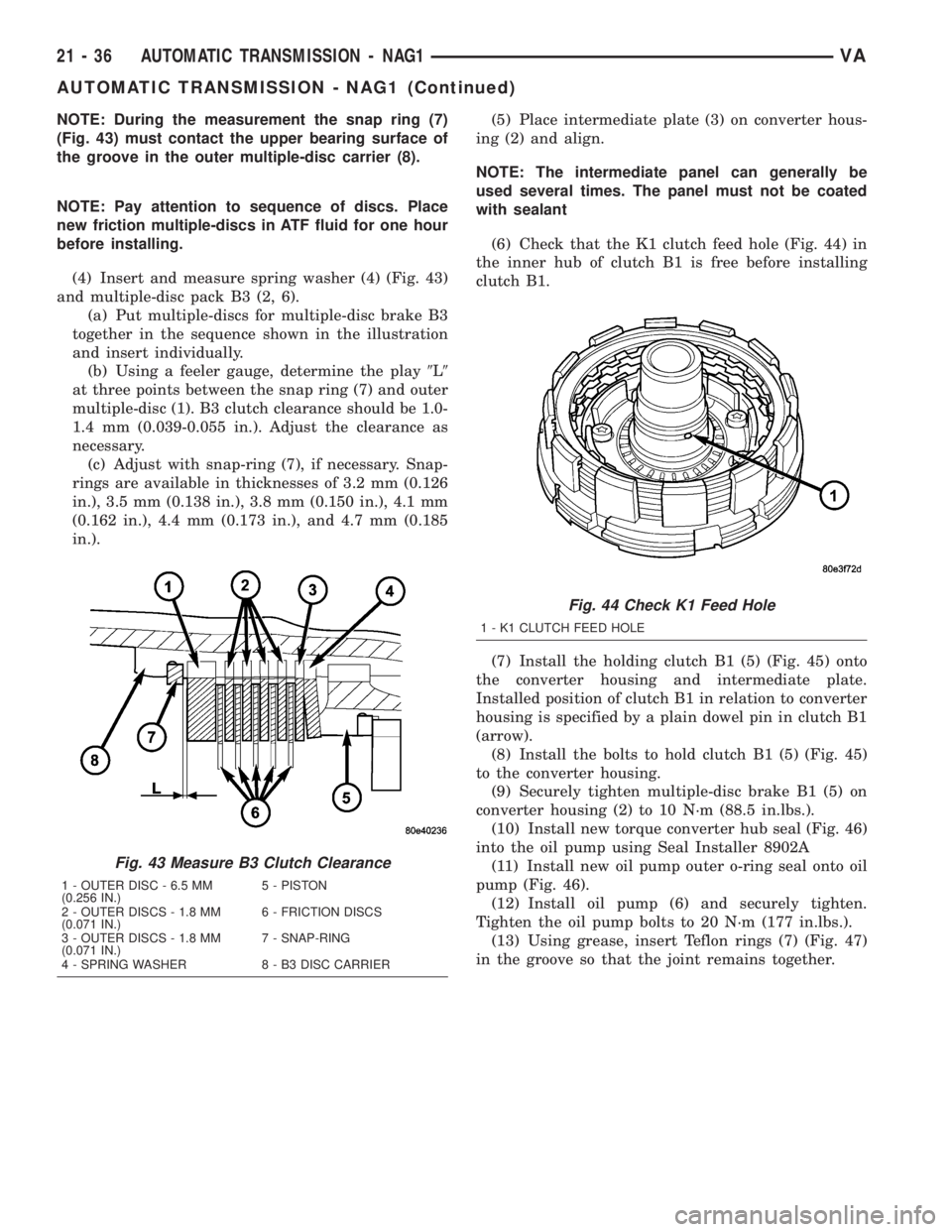
NOTE: During the measurement the snap ring (7)
(Fig. 43) must contact the upper bearing surface of
the groove in the outer multiple-disc carrier (8).
NOTE: Pay attention to sequence of discs. Place
new friction multiple-discs in ATF fluid for one hour
before installing.
(4) Insert and measure spring washer (4) (Fig. 43)
and multiple-disc pack B3 (2, 6).
(a) Put multiple-discs for multiple-disc brake B3
together in the sequence shown in the illustration
and insert individually.
(b) Using a feeler gauge, determine the play9L9
at three points between the snap ring (7) and outer
multiple-disc (1). B3 clutch clearance should be 1.0-
1.4 mm (0.039-0.055 in.). Adjust the clearance as
necessary.
(c) Adjust with snap-ring (7), if necessary. Snap-
rings are available in thicknesses of 3.2 mm (0.126
in.), 3.5 mm (0.138 in.), 3.8 mm (0.150 in.), 4.1 mm
(0.162 in.), 4.4 mm (0.173 in.), and 4.7 mm (0.185
in.).(5) Place intermediate plate (3) on converter hous-
ing (2) and align.
NOTE: The intermediate panel can generally be
used several times. The panel must not be coated
with sealant
(6) Check that the K1 clutch feed hole (Fig. 44) in
the inner hub of clutch B1 is free before installing
clutch B1.
(7) Install the holding clutch B1 (5) (Fig. 45) onto
the converter housing and intermediate plate.
Installed position of clutch B1 in relation to converter
housing is specified by a plain dowel pin in clutch B1
(arrow).
(8) Install the bolts to hold clutch B1 (5) (Fig. 45)
to the converter housing.
(9) Securely tighten multiple-disc brake B1 (5) on
converter housing (2) to 10 N´m (88.5 in.lbs.).
(10) Install new torque converter hub seal (Fig. 46)
into the oil pump using Seal Installer 8902A
(11) Install new oil pump outer o-ring seal onto oil
pump (Fig. 46).
(12) Install oil pump (6) and securely tighten.
Tighten the oil pump bolts to 20 N´m (177 in.lbs.).
(13) Using grease, insert Teflon rings (7) (Fig. 47)
in the groove so that the joint remains together.
Fig. 43 Measure B3 Clutch Clearance
1 - OUTER DISC - 6.5 MM
(0.256 IN.)5 - PISTON
2 - OUTER DISCS - 1.8 MM
(0.071 IN.)6 - FRICTION DISCS
3 - OUTER DISCS - 1.8 MM
(0.071 IN.)7 - SNAP-RING
4 - SPRING WASHER 8 - B3 DISC CARRIER
Fig. 44 Check K1 Feed Hole
1 - K1 CLUTCH FEED HOLE
21 - 36 AUTOMATIC TRANSMISSION - NAG1VA
AUTOMATIC TRANSMISSION - NAG1 (Continued)
Page 922 of 1232
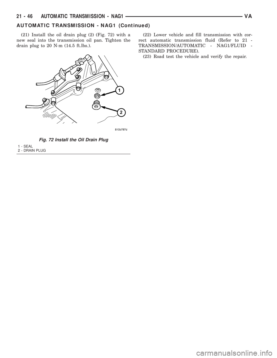
(21) Install the oil drain plug (2) (Fig. 72) with a
new seal into the transmission oil pan. Tighten the
drain plug to 20 N´m (14.5 ft.lbs.).(22) Lower vehicle and fill transmission with cor-
rect automatic transmission fluid (Refer to 21 -
TRANSMISSION/AUTOMATIC - NAG1/FLUID -
STANDARD PROCEDURE).
(23) Road test the vehicle and verify the repair.
Fig. 72 Install the Oil Drain Plug
1 - SEAL
2 - DRAIN PLUG
21 - 46 AUTOMATIC TRANSMISSION - NAG1VA
AUTOMATIC TRANSMISSION - NAG1 (Continued)
Page 951 of 1232
ASSEMBLY
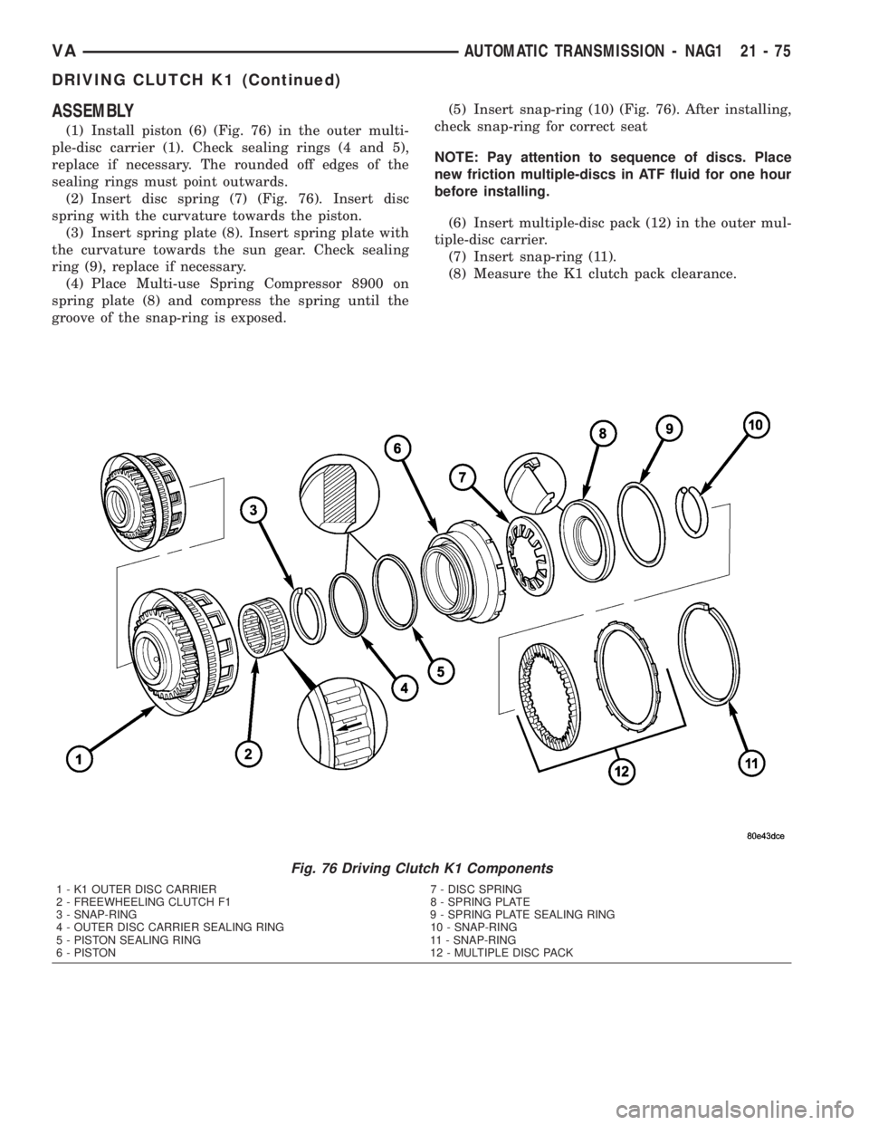
(1) Install piston (6) (Fig. 76) in the outer multi-
ple-disc carrier (1). Check sealing rings (4 and 5),
replace if necessary. The rounded off edges of the
sealing rings must point outwards.
(2) Insert disc spring (7) (Fig. 76). Insert disc
spring with the curvature towards the piston.
(3) Insert spring plate (8). Insert spring plate with
the curvature towards the sun gear. Check sealing
ring (9), replace if necessary.
(4) Place Multi-use Spring Compressor 8900 on
spring plate (8) and compress the spring until the
groove of the snap-ring is exposed.(5) Insert snap-ring (10) (Fig. 76). After installing,
check snap-ring for correct seat
NOTE: Pay attention to sequence of discs. Place
new friction multiple-discs in ATF fluid for one hour
before installing.
(6) Insert multiple-disc pack (12) in the outer mul-
tiple-disc carrier.
(7) Insert snap-ring (11).
(8) Measure the K1 clutch pack clearance.
Fig. 76 Driving Clutch K1 Components
1 - K1 OUTER DISC CARRIER 7 - DISC SPRING
2 - FREEWHEELING CLUTCH F1 8 - SPRING PLATE
3 - SNAP-RING 9 - SPRING PLATE SEALING RING
4 - OUTER DISC CARRIER SEALING RING 10 - SNAP-RING
5 - PISTON SEALING RING 11 - SNAP-RING
6 - PISTON 12 - MULTIPLE DISC PACK
VAAUTOMATIC TRANSMISSION - NAG1 21 - 75
DRIVING CLUTCH K1 (Continued)
Page 954 of 1232
ASSEMBLY
(1) Install piston (6) (Fig. 81) in outer multiple-
disc carrier. Inspect seals (4 and 5), replace if neces-
sary. The rounded edges of the seals must point to
the outside.
(2) Insert disk spring (7) and spring retainer (9).
Insert disk spring (7) with curved side pointing
toward spring retainer (9). Inspect seal (8) (Fig. 81),
replace if necessary.
(3) Place Multi-use Spring Compressor 8900 (Fig.
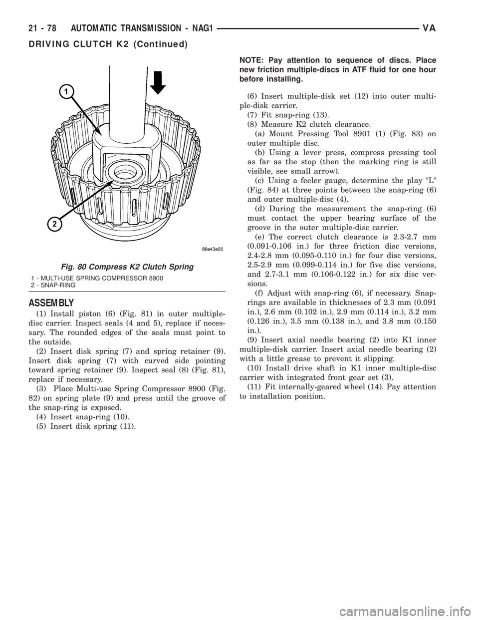
82) on spring plate (9) and press until the groove of
the snap-ring is exposed.
(4) Insert snap-ring (10).
(5) Insert disk spring (11).NOTE: Pay attention to sequence of discs. Place
new friction multiple-discs in ATF fluid for one hour
before installing.
(6) Insert multiple-disk set (12) into outer multi-
ple-disk carrier.
(7) Fit snap-ring (13).
(8) Measure K2 clutch clearance.
(a) Mount Pressing Tool 8901 (1) (Fig. 83) on
outer multiple disc.
(b) Using a lever press, compress pressing tool
as far as the stop (then the marking ring is still
visible, see small arrow).
(c) Using a feeler gauge, determine the play9L9
(Fig. 84) at three points between the snap-ring (6)
and outer multiple-disc (4).
(d) During the measurement the snap-ring (6)
must contact the upper bearing surface of the
groove in the outer multiple-disc carrier.
(e) The correct clutch clearance is 2.3-2.7 mm
(0.091-0.106 in.) for three friction disc versions,
2.4-2.8 mm (0.095-0.110 in.) for four disc versions,
2.5-2.9 mm (0.099-0.114 in.) for five disc versions,
and 2.7-3.1 mm (0.106-0.122 in.) for six disc ver-
sions.
(f) Adjust with snap-ring (6), if necessary. Snap-
rings are available in thicknesses of 2.3 mm (0.091
in.), 2.6 mm (0.102 in.), 2.9 mm (0.114 in.), 3.2 mm
(0.126 in.), 3.5 mm (0.138 in.), and 3.8 mm (0.150
in.).
(9) Insert axial needle bearing (2) into K1 inner
multiple-disk carrier. Insert axial needle bearing (2)
with a little grease to prevent it slipping.
(10) Install drive shaft in K1 inner multiple-disc
carrier with integrated front gear set (3).
(11) Fit internally-geared wheel (14). Pay attention
to installation position.
Fig. 80 Compress K2 Clutch Spring
1 - MULTI-USE SPRING COMPRESSOR 8900
2 - SNAP-RING
21 - 78 AUTOMATIC TRANSMISSION - NAG1VA
DRIVING CLUTCH K2 (Continued)