2005 MERCEDES-BENZ SPRINTER oil temperature
[x] Cancel search: oil temperaturePage 174 of 1232
Except for the indications provided within the
multi-function indicator LCD unit, each indicator in
the EMIC is illuminated by a dedicated LED that is
soldered onto the EMIC electronic circuit board.
Cluster illumination is accomplished by dimmable
LED back lighting, which illuminates the gauges for
visibility when the exterior lighting is turned on. The
cluster general illumination LED units are also sol-
dered onto the EMIC electronic circuit board. The
LED units are not available for service replacement
and, if damaged or faulty, the entire EMIC must be
replaced.
Hard wired circuitry connects the EMIC to the
electrical system of the vehicle. These hard wired cir-cuits are integral to the vehicle wire harnesses,
which are routed throughout the vehicle and retained
by many different methods. These circuits may be
connected to each other, to the vehicle electrical sys-
tem and to the EMIC through the use of a combina-
tion of soldered splices, splice block connectors, and
many different types of wire harness terminal con-
nectors and insulators. Refer to the appropriate wir-
ing information. The wiring information includes
wiring diagrams, proper wire and connector repair
procedures, further details on wire harness routing
and retention, as well as pin-out and location views
for the various wire harness connectors, splices and
grounds.
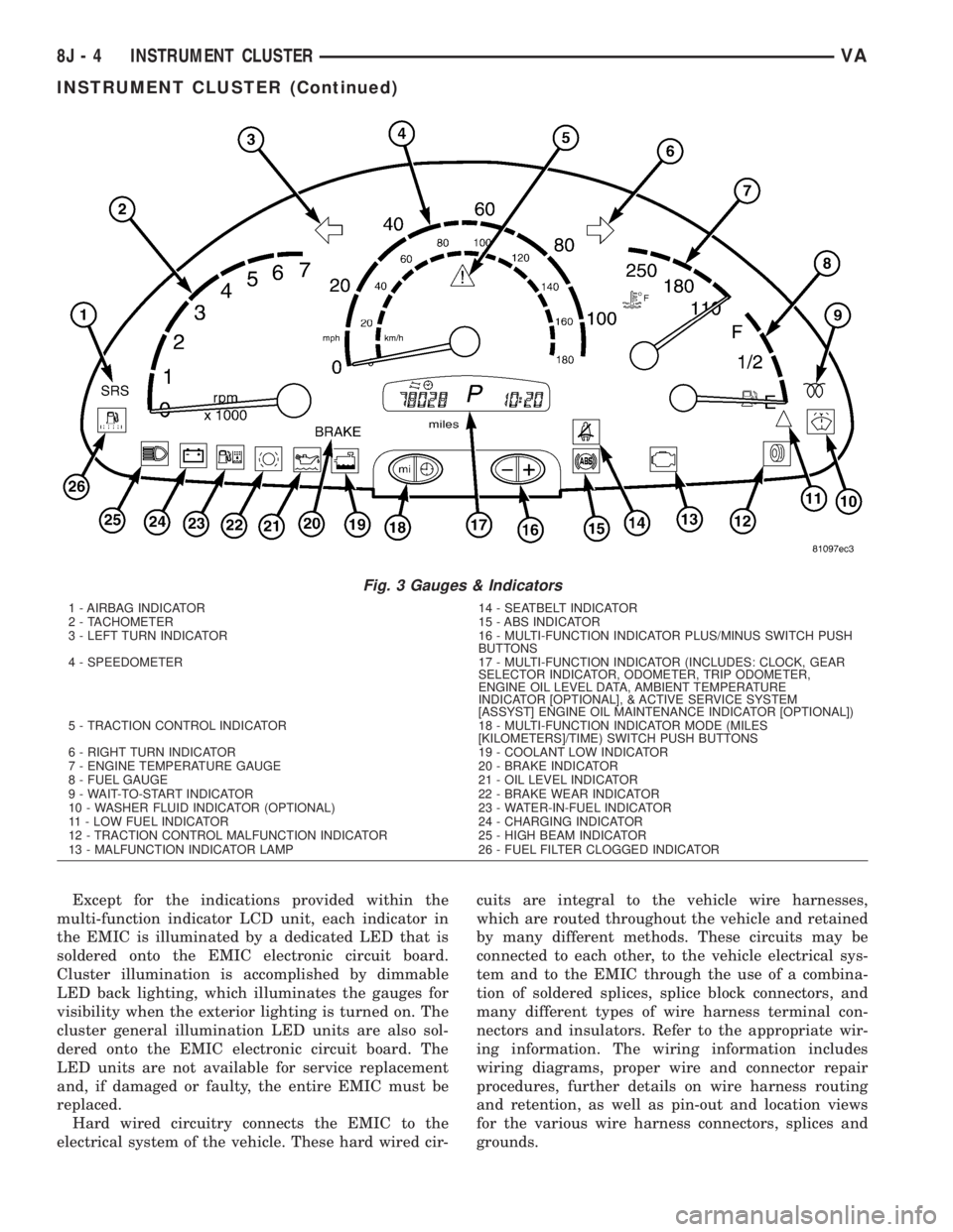
Fig. 3 Gauges & Indicators
1 - AIRBAG INDICATOR 14 - SEATBELT INDICATOR
2 - TACHOMETER 15 - ABS INDICATOR
3 - LEFT TURN INDICATOR 16 - MULTI-FUNCTION INDICATOR PLUS/MINUS SWITCH PUSH
BUTTONS
4 - SPEEDOMETER 17 - MULTI-FUNCTION INDICATOR (INCLUDES: CLOCK, GEAR
SELECTOR INDICATOR, ODOMETER, TRIP ODOMETER,
ENGINE OIL LEVEL DATA, AMBIENT TEMPERATURE
INDICATOR [OPTIONAL], & ACTIVE SERVICE SYSTEM
[ASSYST] ENGINE OIL MAINTENANCE INDICATOR [OPTIONAL])
5 - TRACTION CONTROL INDICATOR 18 - MULTI-FUNCTION INDICATOR MODE (MILES
[KILOMETERS]/TIME) SWITCH PUSH BUTTONS
6 - RIGHT TURN INDICATOR 19 - COOLANT LOW INDICATOR
7 - ENGINE TEMPERATURE GAUGE 20 - BRAKE INDICATOR
8 - FUEL GAUGE 21 - OIL LEVEL INDICATOR
9 - WAIT-TO-START INDICATOR 22 - BRAKE WEAR INDICATOR
10 - WASHER FLUID INDICATOR (OPTIONAL) 23 - WATER-IN-FUEL INDICATOR
11 - LOW FUEL INDICATOR 24 - CHARGING INDICATOR
12 - TRACTION CONTROL MALFUNCTION INDICATOR 25 - HIGH BEAM INDICATOR
13 - MALFUNCTION INDICATOR LAMP 26 - FUEL FILTER CLOGGED INDICATOR
8J - 4 INSTRUMENT CLUSTERVA
INSTRUMENT CLUSTER (Continued)
Page 189 of 1232
ule (ECM) over the Controller Area Network (CAN)
data bus. The low oil level indicator Light Emitting
Diode (LED) is completely controlled by the instru-
ment cluster logic circuit, and that logic will only
allow this indicator to operate when the instrument
cluster detects that the ignition switch is in the On
position. Therefore, the LED will always be off when
the ignition switch is in any position except On. The
LED only illuminates when it is provided a path to
ground by the instrument cluster transistor. The
instrument cluster will turn on the low oil level indi-
cator for the following reasons:
²Bulb Test- Each time the ignition switch is
turned to the On position the low oil level indicator
is illuminated for about two seconds as a bulb test.
²Engine Oil Level Low Message- Once the
engine has been started, each time the cluster
receives a message from the ECM indicating that the
engine oil level is at or near the ªMinimumº mark on
the dipstick, the low oil level indicator is illuminated.
The indicator remains illuminated briefly at first, but
will remain illuminated for longer periods as subse-
quent messages indicate that the oil level has
dropped further. Eventually, the indicator will
remain illuminated solid until the engine oil level is
corrected, or until the ignition switch is turned to the
Off position, whichever occurs first.
The instrument cluster also supplements the oil level
indicator by displaying an engine oil icon along with
alpha-numeric messages in the multi-function indicator
Liquid Crystal Display (LCD) advising the vehicle oper-
ator how much oil is required to correct the engine oil
level, and when the ªMaximumº engine oil level has
been exceeded. See the owner's manual in the vehicle
glove box for more information on this feature.
The ECM continually monitors the engine oil level
and temperature sensor to determine the engine oil
level. The ECM then sends the proper engine oil
level messages to the instrument cluster. If the
instrument cluster turns on the indicator after the
bulb test, even after the engine oil level is sufficient,
it may indicate that the engine or the engine oiling
system requires service. For proper diagnosis of the
engine oil level and temperature sensor, the ECM,
the CAN data bus, or the electronic message inputs
to the instrument cluster that control the low oil
level indicator, a DRBIIItscan tool is required. Refer
to the appropriate diagnostic information.
MAINTENANCE INDICATOR
DESCRIPTION
An Active Service SYSTem (ASSYST) engine oil main-
tenance indicator is optional equipment on all instru-
ment clusters. In vehicles so equipped, a second,dedicated ASSYST microprocessor is integral to the
cluster electronic circuit board. The ASSYST indications
are displayed and can be toggled with the clock indica-
tion on the right side of the multi-function indicator
Liquid Crystal Display (LCD) located near the lower
edge of the instrument cluster, directly below the speed-
ometer. The ASSYST displays include numeric values
combined with several icons to indicate actual engine oil
level, and reminders in time (days) or distance (miles or
kilometers) until the next required engine oil mainte-
nance is anticipated. ASSYST also provides several
audible indications using the electronic tone generator
on the instrument cluster circuit board to supplement
these visual displays.
The indications of the ASSYST engine oil mainte-
nance indicator are not visible when the LCD is not illu-
minated. When illuminated, the ASSYST indications
appear as dark characters and icons silhouetted against
an amber field. When the exterior lighting is turned Off,
the display is illuminated at maximum brightness.
When the exterior lighting is turned On, the display
illumination level can be adjusted in concert with the
cluster general illumination lighting using the ª+º (plus)
and ª2º (minus) multi-function indicator push buttons.
The ASSYST engine oil maintenance indicator is ser-
viced as a unit with the instrument cluster.
OPERATION
The ASSYST engine oil maintenance indicator micro-
processor uses numerous criteria besides time and mile-
age to evaluate vehicle maintenance requirements. Time
data is taken from the electronic digital clock integral to
the instrument cluster. Vehicle distance data is obtained
from the Controller Antilock Brake (CAB) over the Con-
troller Area Network (CAN) data bus. Coolant tempera-
ture, engine oil temperature, engine oil level, engine oil
quality, engine speed, and engine load data are obtained
from the Engine Control Module (ECM) over the CAN
data bus. Using all of the available data and internal
programming, the ASSYST microprocessor then calcu-
lates the estimated time and distance to the next
required engine oil maintenance interval. The ASSYST
uses the multi-function indicator LCD to display that
data and, when necessary, issues audible alerts to the
vehicle operator through the electronic tone generator
on the cluster circuit board.
See the owner's manual in the vehicle glove box for
more information on the features, use, operation and
resetting procedures for the ASSYST maintenance
computer. Proper diagnosis and testing of the
ASSYST engine oil maintenance computer, the CAN
data bus and the electronic data bus message inputs
to the EMIC that are used by the ASSYST computer
for its calculations requires the use of a DRBIIIt
scan tool. Refer to the appropriate diagnostic infor-
mation.
VAINSTRUMENT CLUSTER 8J - 19
LOW OIL LEVEL INDICATOR (Continued)
Page 191 of 1232
OPERATION
The multi-function indicator has several display
capabilities including odometer, trip odometer, clock,
engine oil level data, gear selector indicator
(PRNDL), certain diagnostic information and, on
vehicles so equipped, an optional Active Service SYS-
Tem (ASSYST) engine oil maintenance indicator and
an optional outside ambient temperature indicator.
The multi-function indicator is completely controlled
by the instrument cluster logic circuit, and that logic
will allow this indication to be viewed whenever the
multi-function indicator Liquid Crystal Display
(LCD) is activated. Therefore, the indicator remains
functional regardless of the ignition switch position.
With the ignition switch in the Off or Accessory posi-
tions and the key removed from the ignition lock cyl-
inder, the display is activated when the park lamps
are turned On or, for about thirty seconds after any
one of the multi-function indicator switch push but-
tons is depressed. Otherwise, the display unit is
active for about thirty seconds after the key is
inserted into the ignition lock cylinder, and inactive
about thirty seconds after the key is removed from
the ignition lock cylinder.
The multi-function indicator ªmiº (miles) or
ªkmº(kilometers) switch push button is used to con-
trol the odometer/trip odometer display modes. The
multi-function indicator clock switch push button is
used to control the clock/outside temperature display
modes. The multi-function indicator ª+º (plus) and
ª2º (minus) switch push buttons are used to adjust
the cluster general illumination dimming level, the
clock, and other cluster settings. See the owner's
manual in the vehicle glove box for more information
on the features, use, operation and setting proce-
dures for the various standard and optional multi-
function indicator displays.
Proper testing of the multi-function indicator LCD
unit, the CAN data bus and the electronic data bus
message inputs to the instrument cluster that control
some of the multi-function indicator functions
requires the use of a DRBIIItscan tool. Refer to the
appropriate diagnostic information. Additional details
for the odometer/trip odometer, the clock, the gear
selector indicator, the ambient temperature indicator
and the ASSYST warning and reminder functions of
the multi-function indicator may be found elsewhere
in this service information.
ODOMETER
DESCRIPTION
An odometer and trip odometer are standard
equipment in all instrument clusters. The odometer
and trip odometer values are displayed on the leftside of the multi-function indicator Liquid Crystal
Display (LCD). The LCD is soldered onto the cluster
electronic circuit board and is visible through a win-
dow with a clear lens located near the lower edge of
the instrument cluster, directly below the speedome-
ter. However, the odometer and trip odometer infor-
mation are not displayed simultaneously. The ªmiº
(miles) or ªkmº (kilometers) switch on the instrument
cluster circuit board toggles the display between
odometer and trip odometer modes by depressing the
switch push button that extends through the lower
edge of the cluster lens, directly below the multi-
function indicator LCD.
The odometer and trip odometer information is
stored in the instrument cluster memory. This infor-
mation can be increased when the proper inputs are
provided to the instrument cluster, but the informa-
tion cannot be decreased. The odometer can display
values up to 999,999 kilometers (999,999 miles). The
odometer latches at these values, and will not roll
over to zero. The trip odometer can display values up
to 999.9 kilometers (999.9 miles) before it rolls over
to zero. The odometer display does not have a deci-
mal point and will not show values less than a full
unit (kilometer or mile), while the trip odometer dis-
play does have a decimal point and will show tenths
of a unit (kilometer or mile). The unit of measure
(kilometers or miles) for the odometer and trip odom-
eter display is imprinted on the cluster overlay below
the left end of the LCD. The unit of measure for the
instrument cluster odometer/trip odometer is selected
at the time that it is manufactured, and cannot be
changed.
The indications of the odometer/trip odometer are
not visible when the LCD is not illuminated. When
illuminated the indications appear as dark charac-
ters silhouetted against an amber field. When the
exterior lighting is turned Off, the display is illumi-
nated at maximum brightness. When the exterior
lighting is turned On the display illumination level
can be adjusted in concert with the cluster general
illumination lighting using the plus and minus multi-
function indicator push buttons. The odometer has a
ªRental Carº mode, which will activate the multi-
function indicator LCD and illuminate the odometer
information for about thirty seconds after one of the
multi-function indicator push buttons is momentarily
depressed, or after the key is inserted into the igni-
tion switch lock cylinder with the ignition switch in
the Off position.
The odometer/trip odometer and the miles/kilome-
ters switch, and the miles/kilometers switch push
button are serviced as a unit with the instrument
cluster.
VAINSTRUMENT CLUSTER 8J - 21
MULTI-FUNCTION INDICATOR (Continued)
Page 317 of 1232
8W-02 COMPONENT INDEX
Component Page
A/C Auxiliary Fan Relay................ 8W-42
A/C Auxiliary Fan..................... 8W-42
A/C Compressor Clutch................. 8W-42
A/C Control Module-Roof................ 8W-42
A/C Fan Switch....................... 8W-42
A/C Switch-Roof...................... 8W-42
Accelerator Pedal Position Sensor......... 8W-30
Air Outlet Temperature Sensor........... 8W-42
Airbag Control Module................. 8W-43
Airbag Squibs........................ 8W-43
Ambient Temperature Sensor............ 8W-42
Ash Receiver Lamp.................... 8W-44
Automatic Temperature Control Module.... 8W-42
Auxiliary Heater Relay................. 8W-42
Auxiliary Heater Switch................ 8W-42
Battery Relay-Auxiliary................ 8W-20
Batteries............................ 8W-20
Beam Select Switch.................... 8W-50
Blower Motors........................ 8W-42
Body Plug Connector................... 8W-11
Boost Pressure Sensor.................. 8W-30
Boost Pressure Solenoid................ 8W-30
Brake Fluid Level Switch............... 8W-35
Brake Lamp Switch.................... 8W-35
Brake Wear Sensors................... 8W-35
Cabin Heater Assembly................. 8W-42
Cabin Heater Control Module............ 8W-42
Camshaft Position Sensor............... 8W-30
Center High Mounted Stop Lamp......... 8W-51
Central Timer Module.................. 8W-45
Cigar Lighter Lamp................... 8W-44
Cigar Lighter......................... 8W-41
Circulation Pump Diode................ 8W-42
Circulation Pump Relay................ 8W-42
Circulation Pump..................... 8W-42
Clockspring....................... 8W-41, 43
Contact Switch Door-Tailgate............ 8W-44
Controller Antilock Brake............... 8W-35
Courtesy Lamps...................... 8W-44
Crankcase Heater..................... 8W-30
Crankshaft Position Sensor.............. 8W-30
Ctel Antenna Connector................ 8W-55
Ctel Connector..................... 8W-47, 55
Cylinder Lock Switch-Driver............. 8W-61
D+ Relay No. 1....................... 8W-10
D+ Relay No. 2....................... 8W-11
Data Link Connector................... 8W-18
Daytime Running Lamp Relays........... 8W-50
Differential Lock Solenoid Valve.......... 8W-31
Dome Lamp.......................... 8W-44
Door Jamb Switches................... 8W-44
Door Lock Motor/Ajar Switch Assemblies . . . 8W-61Component Page
Dosing Pump......................... 8W-42
EGR Valve........................... 8W-30
Engine Control Module................. 8W-30
Engine Control Relay.................. 8W-31
Engine Coolant Level Switch............. 8W-30
Engine Coolant Temperature Sensor....... 8W-30
Engine Oil Sensor..................... 8W-30
Evaporator Temperature Sensor.......... 8W-42
Fan Stage 1 Relay..................... 8W-42
Fog Lamp Relay...................... 8W-50
Fog Lamp Switch..................... 8W-50
Fuel Injectors........................ 8W-30
Fuel Level Sensor..................... 8W-30
Fuel Pressure Sensor.................. 8W-30
Fuel Pressure Solenoid................. 8W-30
Fuel Shutdown Solenoid................ 8W-30
Fuel Temperature Sensor............... 8W-30
Fuses............................ 8W-10, 11
Fuse Blocks.......................... 8W-10
Fuse/Relay Block...................... 8W-11
Fused Ignition Switch Run-Start Relay..... 8W-11
Grounds............................ 8W-70
Generator........................... 8W-20
Glow Plug Control Module.............. 8W-30
Glow Plugs.......................... 8W-30
Hazard Warning Switch................ 8W-52
Headlamp Adjust Switch................ 8W-50
Headlamp Assemblies............... 8W-50, 52
Headlamp Switch..................... 8W-50
Heat Exchanger Connector.............. 8W-42
Heat Exchanger Switch................. 8W-42
Heated Seat Modules.................. 8W-63
Heated Seat Switches.................. 8W-63
Heater Timer-Auxiliary................. 8W-42
Hood Ajar Switch..................... 8W-39
Horn Relay.......................... 8W-41
Horn Switch......................... 8W-41
Horn............................... 8W-41
Ignition Lock Switch................... 8W-40
Ignition Switch....................... 8W-10
Instrument Cluster.................... 8W-40
Instrument Panel Socket................ 8W-40
Intake Air Temperature Sensor........... 8W-30
Interior Lamps....................... 8W-44
Interior Light Switches................. 8W-44
Interior Lighting Connector.............. 8W-44
Intrusion Sensors..................... 8W-39
Kickdown Switch...................... 8W-30
Lamp Relays......................... 8W-50
License Plate Lamps................... 8W-51
Locker Switches...................... 8W-31
Low Fuel Pressure Sensor............... 8W-30
VA8W-02 COMPONENT INDEX 8W - 02 - 1
Page 435 of 1232
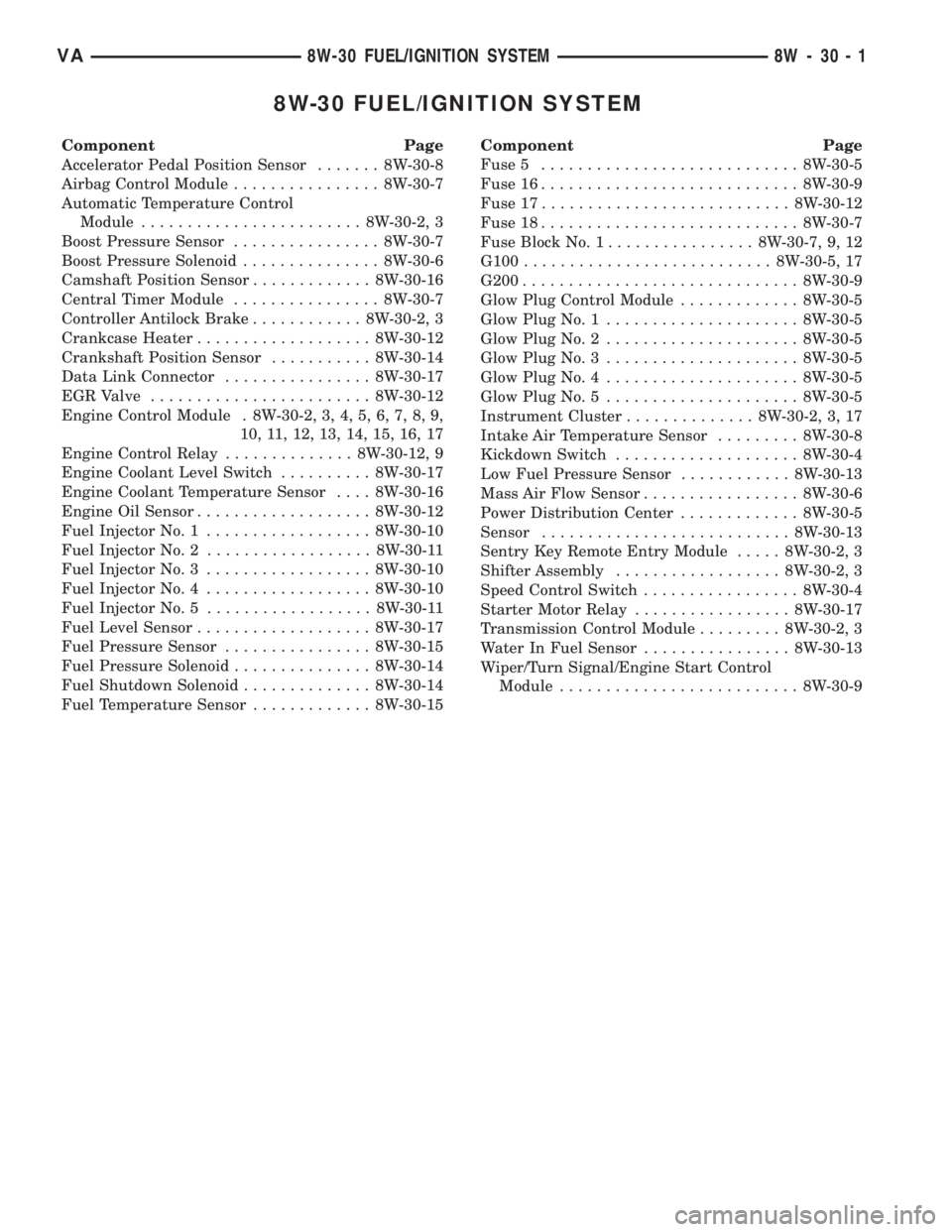
8W-30 FUEL/IGNITION SYSTEM
Component Page
Accelerator Pedal Position Sensor....... 8W-30-8
Airbag Control Module................ 8W-30-7
Automatic Temperature Control
Module........................ 8W-30-2, 3
Boost Pressure Sensor................ 8W-30-7
Boost Pressure Solenoid............... 8W-30-6
Camshaft Position Sensor............. 8W-30-16
Central Timer Module................ 8W-30-7
Controller Antilock Brake............ 8W-30-2, 3
Crankcase Heater................... 8W-30-12
Crankshaft Position Sensor........... 8W-30-14
Data Link Connector................ 8W-30-17
EGR Valve........................ 8W-30-12
Engine Control Module . 8W-30-2, 3, 4, 5, 6, 7, 8, 9,
10, 11, 12, 13, 14, 15, 16, 17
Engine Control Relay.............. 8W-30-12, 9
Engine Coolant Level Switch.......... 8W-30-17
Engine Coolant Temperature Sensor.... 8W-30-16
Engine Oil Sensor................... 8W-30-12
Fuel Injector No. 1.................. 8W-30-10
Fuel Injector No. 2.................. 8W-30-11
Fuel Injector No. 3.................. 8W-30-10
Fuel Injector No. 4.................. 8W-30-10
Fuel Injector No. 5.................. 8W-30-11
Fuel Level Sensor................... 8W-30-17
Fuel Pressure Sensor................ 8W-30-15
Fuel Pressure Solenoid............... 8W-30-14
Fuel Shutdown Solenoid.............. 8W-30-14
Fuel Temperature Sensor............. 8W-30-15Component Page
Fuse 5............................ 8W-30-5
Fuse 16............................ 8W-30-9
Fuse 17........................... 8W-30-12
Fuse 18............................ 8W-30-7
Fuse Block No. 1................ 8W-30-7, 9, 12
G100........................... 8W-30-5, 17
G200.............................. 8W-30-9
Glow Plug Control Module............. 8W-30-5
Glow Plug No. 1..................... 8W-30-5
Glow Plug No. 2..................... 8W-30-5
Glow Plug No. 3..................... 8W-30-5
Glow Plug No. 4..................... 8W-30-5
Glow Plug No. 5..................... 8W-30-5
Instrument Cluster.............. 8W-30-2, 3, 17
Intake Air Temperature Sensor......... 8W-30-8
Kickdown Switch.................... 8W-30-4
Low Fuel Pressure Sensor............ 8W-30-13
Mass Air Flow Sensor................. 8W-30-6
Power Distribution Center............. 8W-30-5
Sensor........................... 8W-30-13
Sentry Key Remote Entry Module..... 8W-30-2, 3
Shifter Assembly.................. 8W-30-2, 3
Speed Control Switch................. 8W-30-4
Starter Motor Relay................. 8W-30-17
Transmission Control Module......... 8W-30-2, 3
Water In Fuel Sensor................ 8W-30-13
Wiper/Turn Signal/Engine Start Control
Module.......................... 8W-30-9
VA8W-30 FUEL/IGNITION SYSTEM 8W - 30 - 1
Page 628 of 1232
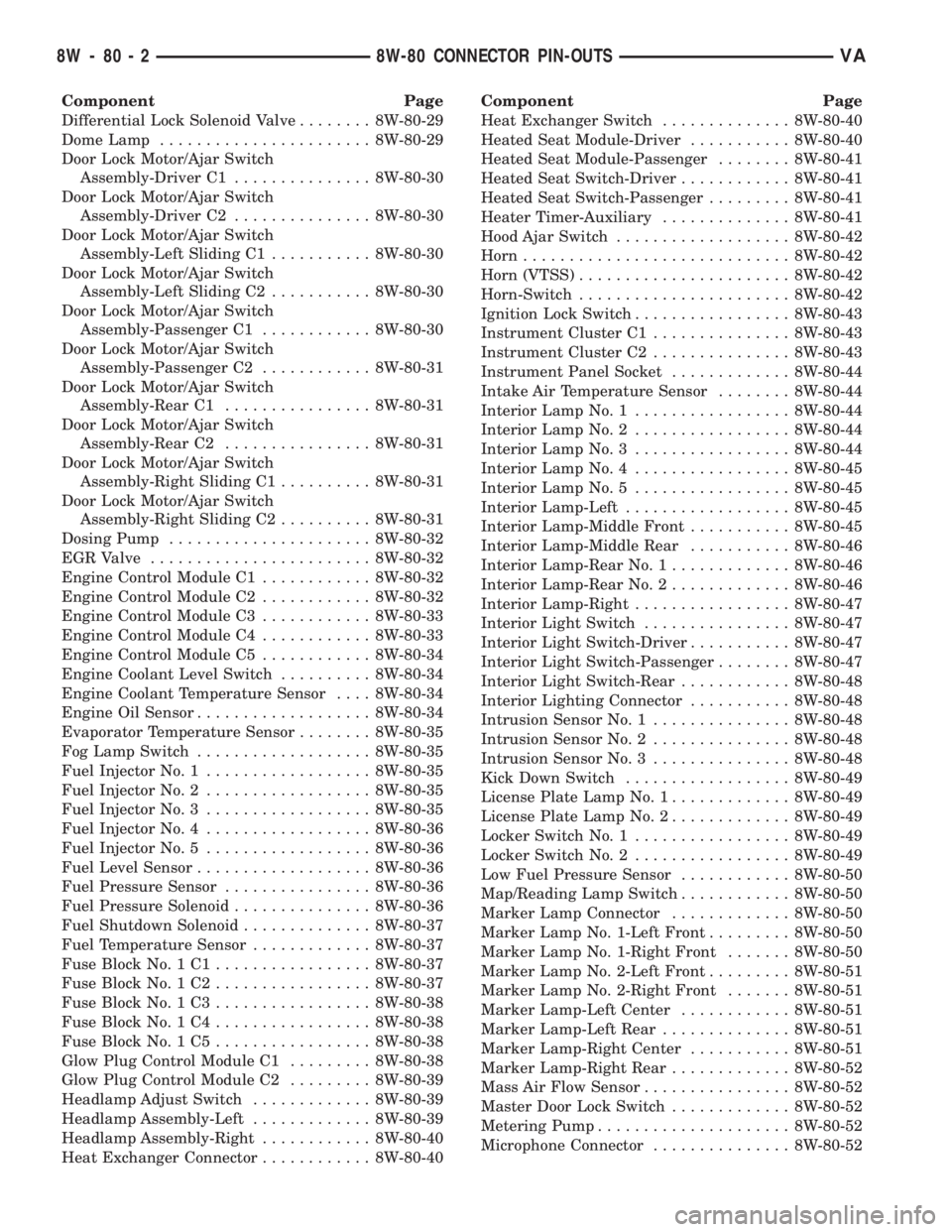
Component Page
Differential Lock Solenoid Valve........ 8W-80-29
Dome Lamp....................... 8W-80-29
Door Lock Motor/Ajar Switch
Assembly-Driver C1............... 8W-80-30
Door Lock Motor/Ajar Switch
Assembly-Driver C2............... 8W-80-30
Door Lock Motor/Ajar Switch
Assembly-Left Sliding C1........... 8W-80-30
Door Lock Motor/Ajar Switch
Assembly-Left Sliding C2........... 8W-80-30
Door Lock Motor/Ajar Switch
Assembly-Passenger C1............ 8W-80-30
Door Lock Motor/Ajar Switch
Assembly-Passenger C2............ 8W-80-31
Door Lock Motor/Ajar Switch
Assembly-Rear C1................ 8W-80-31
Door Lock Motor/Ajar Switch
Assembly-Rear C2................ 8W-80-31
Door Lock Motor/Ajar Switch
Assembly-Right Sliding C1.......... 8W-80-31
Door Lock Motor/Ajar Switch
Assembly-Right Sliding C2.......... 8W-80-31
Dosing Pump...................... 8W-80-32
EGR Valve........................ 8W-80-32
Engine Control Module C1............ 8W-80-32
Engine Control Module C2............ 8W-80-32
Engine Control Module C3............ 8W-80-33
Engine Control Module C4............ 8W-80-33
Engine Control Module C5............ 8W-80-34
Engine Coolant Level Switch.......... 8W-80-34
Engine Coolant Temperature Sensor.... 8W-80-34
Engine Oil Sensor................... 8W-80-34
Evaporator Temperature Sensor........ 8W-80-35
Fog Lamp Switch................... 8W-80-35
Fuel Injector No. 1.................. 8W-80-35
Fuel Injector No. 2.................. 8W-80-35
Fuel Injector No. 3.................. 8W-80-35
Fuel Injector No. 4.................. 8W-80-36
Fuel Injector No. 5.................. 8W-80-36
Fuel Level Sensor................... 8W-80-36
Fuel Pressure Sensor................ 8W-80-36
Fuel Pressure Solenoid............... 8W-80-36
Fuel Shutdown Solenoid.............. 8W-80-37
Fuel Temperature Sensor............. 8W-80-37
Fuse Block No. 1 C1................. 8W-80-37
Fuse Block No. 1 C2................. 8W-80-37
Fuse Block No. 1 C3................. 8W-80-38
Fuse Block No. 1 C4................. 8W-80-38
Fuse Block No. 1 C5................. 8W-80-38
Glow Plug Control Module C1......... 8W-80-38
Glow Plug Control Module C2......... 8W-80-39
Headlamp Adjust Switch............. 8W-80-39
Headlamp Assembly-Left............. 8W-80-39
Headlamp Assembly-Right............ 8W-80-40
Heat Exchanger Connector............ 8W-80-40Component Page
Heat Exchanger Switch.............. 8W-80-40
Heated Seat Module-Driver........... 8W-80-40
Heated Seat Module-Passenger........ 8W-80-41
Heated Seat Switch-Driver............ 8W-80-41
Heated Seat Switch-Passenger......... 8W-80-41
Heater Timer-Auxiliary.............. 8W-80-41
Hood Ajar Switch................... 8W-80-42
Horn............................. 8W-80-42
Horn (VTSS)....................... 8W-80-42
Horn-Switch....................... 8W-80-42
Ignition Lock Switch................. 8W-80-43
Instrument Cluster C1............... 8W-80-43
Instrument Cluster C2............... 8W-80-43
Instrument Panel Socket............. 8W-80-44
Intake Air Temperature Sensor........ 8W-80-44
Interior Lamp No. 1................. 8W-80-44
Interior Lamp No. 2................. 8W-80-44
Interior Lamp No. 3................. 8W-80-44
Interior Lamp No. 4................. 8W-80-45
Interior Lamp No. 5................. 8W-80-45
Interior Lamp-Left.................. 8W-80-45
Interior Lamp-Middle Front........... 8W-80-45
Interior Lamp-Middle Rear........... 8W-80-46
Interior Lamp-Rear No. 1............. 8W-80-46
Interior Lamp-Rear No. 2............. 8W-80-46
Interior Lamp-Right................. 8W-80-47
Interior Light Switch................ 8W-80-47
Interior Light Switch-Driver........... 8W-80-47
Interior Light Switch-Passenger........ 8W-80-47
Interior Light Switch-Rear............ 8W-80-48
Interior Lighting Connector........... 8W-80-48
Intrusion Sensor No. 1............... 8W-80-48
Intrusion Sensor No. 2............... 8W-80-48
Intrusion Sensor No. 3............... 8W-80-48
Kick Down Switch.................. 8W-80-49
License Plate Lamp No. 1............. 8W-80-49
License Plate Lamp No. 2............. 8W-80-49
Locker Switch No. 1................. 8W-80-49
Locker Switch No. 2................. 8W-80-49
Low Fuel Pressure Sensor............ 8W-80-50
Map/Reading Lamp Switch............ 8W-80-50
Marker Lamp Connector............. 8W-80-50
Marker Lamp No. 1-Left Front......... 8W-80-50
Marker Lamp No. 1-Right Front....... 8W-80-50
Marker Lamp No. 2-Left Front......... 8W-80-51
Marker Lamp No. 2-Right Front....... 8W-80-51
Marker Lamp-Left Center............ 8W-80-51
Marker Lamp-Left Rear.............. 8W-80-51
Marker Lamp-Right Center........... 8W-80-51
Marker Lamp-Right Rear............. 8W-80-52
Mass Air Flow Sensor................ 8W-80-52
Master Door Lock Switch............. 8W-80-52
Metering Pump..................... 8W-80-52
Microphone Connector............... 8W-80-52
8W - 80 - 2 8W-80 CONNECTOR PIN-OUTSVA
Page 659 of 1232
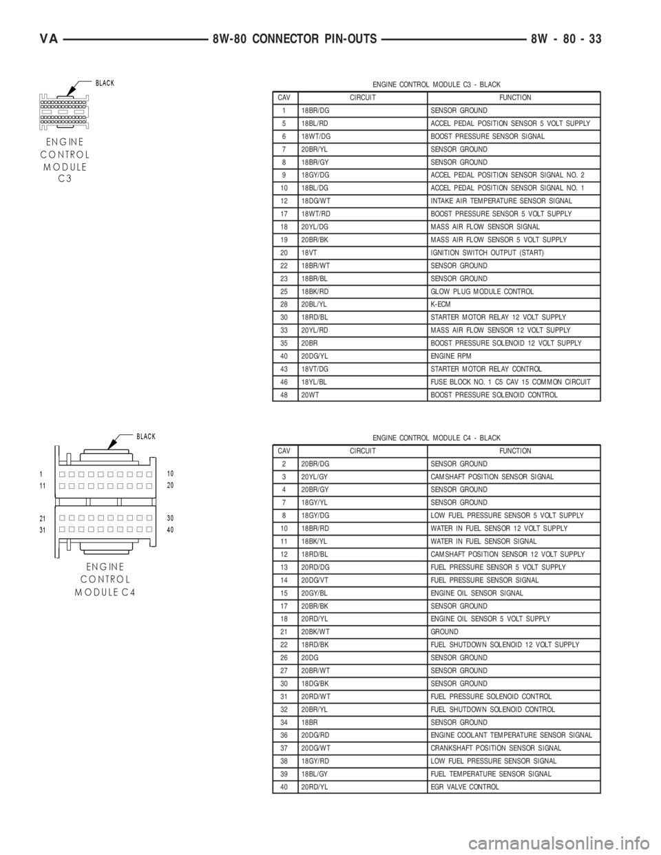
ENGINE CONTROL MODULE C3 - BLACK
CAV CIRCUIT FUNCTION
1 18BR/DG SENSOR GROUND
5 18BL/RD ACCEL PEDAL POSITION SENSOR 5 VOLT SUPPLY
6 18WT/DG BOOST PRESSURE SENSOR SIGNAL
7 20BR/YL SENSOR GROUND
8 18BR/GY SENSOR GROUND
9 18GY/DG ACCEL PEDAL POSITION SENSOR SIGNAL NO. 2
10 18BL/DG ACCEL PEDAL POSITION SENSOR SIGNAL NO. 1
12 18DG/WT INTAKE AIR TEMPERATURE SENSOR SIGNAL
17 18WT/RD BOOST PRESSURE SENSOR 5 VOLT SUPPLY
18 20YL/DG MASS AIR FLOW SENSOR SIGNAL
19 20BR/BK MASS AIR FLOW SENSOR 5 VOLT SUPPLY
20 18VT IGNITION SWITCH OUTPUT (START)
22 18BR/WT SENSOR GROUND
23 18BR/BL SENSOR GROUND
25 18BK/RD GLOW PLUG MODULE CONTROL
28 20BL/YL K-ECM
30 18RD/BL STARTER MOTOR RELAY 12 VOLT SUPPLY
33 20YL/RD MASS AIR FLOW SENSOR 12 VOLT SUPPLY
35 20BR BOOST PRESSURE SOLENOID 12 VOLT SUPPLY
40 20DG/YL ENGINE RPM
43 18VT/DG STARTER MOTOR RELAY CONTROL
46 18YL/BL FUSE BLOCK NO. 1 C5 CAV 15 COMMON CIRCUIT
48 20WT BOOST PRESSURE SOLENOID CONTROL
ENGINE CONTROL MODULE C4 - BLACK
CAV CIRCUIT FUNCTION
2 20BR/DG SENSOR GROUND
3 20YL/GY CAMSHAFT POSITION SENSOR SIGNAL
4 20BR/GY SENSOR GROUND
7 18GY/YL SENSOR GROUND
8 18GY/DG LOW FUEL PRESSURE SENSOR 5 VOLT SUPPLY
10 18BR/RD WATER IN FUEL SENSOR 12 VOLT SUPPLY
11 18BK/YL WATER IN FUEL SENSOR SIGNAL
12 18RD/BL CAMSHAFT POSITION SENSOR 12 VOLT SUPPLY
13 20RD/DG FUEL PRESSURE SENSOR 5 VOLT SUPPLY
14 20DG/VT FUEL PRESSURE SENSOR SIGNAL
15 20GY/BL ENGINE OIL SENSOR SIGNAL
17 20BR/BK SENSOR GROUND
18 20RD/YL ENGINE OIL SENSOR 5 VOLT SUPPLY
21 20BK/WT GROUND
22 18RD/BK FUEL SHUTDOWN SOLENOID 12 VOLT SUPPLY
26 20DG SENSOR GROUND
27 20BR/WT SENSOR GROUND
30 18DG/BK SENSOR GROUND
31 20RD/WT FUEL PRESSURE SOLENOID CONTROL
32 20BR/YL FUEL SHUTDOWN SOLENOID CONTROL
34 18BR SENSOR GROUND
36 20DG/RD ENGINE COOLANT TEMPERATURE SENSOR SIGNAL
37 20DG/WT CRANKSHAFT POSITION SENSOR SIGNAL
38 18GY/RD LOW FUEL PRESSURE SENSOR SIGNAL
39 18BL/GY FUEL TEMPERATURE SENSOR SIGNAL
40 20RD/YL EGR VALVE CONTROL
VA8W-80 CONNECTOR PIN-OUTS 8W - 80 - 33
Page 660 of 1232
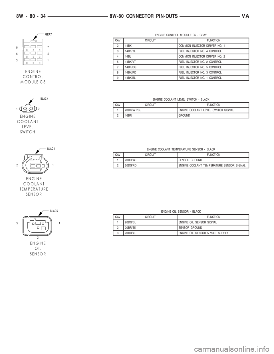
ENGINE CONTROL MODULE C5 - GRAY
CAV CIRCUIT FUNCTION
2 14BK COMMON INJECTOR DRIVER NO. 1
3 14BK/YL FUEL INJECTOR NO. 4 CONTROL
4 14BL COMMON INJECTOR DRIVER NO. 2
5 14BK/VT FUEL INJECTOR NO. 2 CONTROL
7 14BK/DG FUEL INJECTOR NO. 5 CONTROL
8 14BK/RD FUEL INJECTOR NO. 3 CONTROL
9 14BK/BL FUEL INJECTOR NO. 1 CONTROL
ENGINE COOLANT LEVEL SWITCH - BLACK
CAV CIRCUIT FUNCTION
1 20DG/WT/BL ENGINE COOLANT LEVEL SWITCH SIGNAL
2 16BR GROUND
ENGINE COOLANT TEMPERATURE SENSOR - BLACK
CAV CIRCUIT FUNCTION
1 20BR/WT SENSOR GROUND
2 20DG/RD ENGINE COOLANT TEMPERATURE SENSOR SIGNAL
ENGINE OIL SENSOR - BLACK
CAV CIRCUIT FUNCTION
1 20DG/BL ENGINE OIL SENSOR SIGNAL
2 20BR/BK SENSOR GROUND
3 20RD/YL ENGINE OIL SENSOR 5 VOLT SUPPLY
8W - 80 - 34 8W-80 CONNECTOR PIN-OUTSVA