2005 MERCEDES-BENZ SPRINTER tire type
[x] Cancel search: tire typePage 291 of 1232
washer hose fittings cannot be repaired. If these fittings
are faulty or damaged, they must be replaced.
OPERATION
Washer fluid in the washer reservoir is pressurized
and fed by the washer pump/motor through the
washer system plumbing and fittings to the two
washer nozzles. Whenever routing the washer hose
or a wire harness containing a washer hose, it must
be routed away from hot, sharp, or moving parts;
and, sharp bends that might pinch the hose must be
avoided.
WASHER NOZZLE
DESCRIPTION
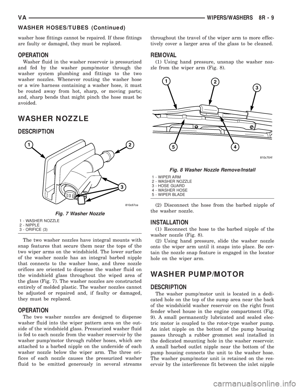
The two washer nozzles have integral mounts with
snap features that secure them near the tops of the
two wiper arms on the windshield. The lower surface
of the washer nozzle has an integral barbed nipple
that connects to the washer hose, and three nozzle
orifices are oriented to dispense the washer fluid on
the windshield glass throughout the wiped area of
the glass (Fig. 7). The washer nozzles are constructed
entirely of molded plastic. The washer nozzles cannot
be adjusted or repaired and, if faulty or damaged,
they must be replaced.
OPERATION
The two washer nozzles are designed to dispense
washer fluid into the wiper pattern area on the out-
side of the windshield glass. Pressurized washer fluid
is fed to each nozzle from the washer reservoir by the
washer pump/motor through rubber hoses, which are
attached to a barbed nipple on the underside of each
washer nozzle below the wiper arm. The three ori-
fices of each nozzle causes the pressurized washer
fluid to be emitted generously in several streamsthroughout the travel of the wiper arm to more effec-
tively cover a larger area of the glass to be cleaned.
REMOVAL
(1) Using hand pressure, unsnap the washer noz-
zle from the wiper arm (Fig. 8).
(2) Disconnect the hose from the barbed nipple of
the washer nozzle.
INSTALLATION
(1) Reconnect the hose to the barbed nipple of the
washer nozzle (Fig. 8).
(2) Using hand pressure, slide the washer nozzle
onto the wiper arm until it snaps into place. Be cer-
tain the nozzle snap feature is engaged in the locator
hole on the wiper arm.
WASHER PUMP/MOTOR
DESCRIPTION
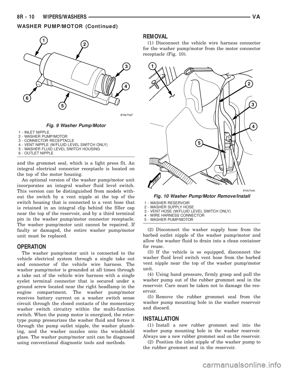
The washer pump/motor unit is located in a dedi-
cated hole on the top of the sump area near the back
of the windshield washer reservoir on the right front
fender wheel house in the engine compartment (Fig.
9). A small permanently lubricated and sealed elec-
tric motor is coupled to the rotor-type washer pump.
An inlet nipple on the bottom of the pump housing
passes through a rubber grommet seal installed in
the dedicated mounting hole in the washer reservoir.
A small barbed outlet nipple near the bottom of the
pump housing connects the unit to the washer hose.
The washer pump/motor unit is retained on the res-
ervoir by the interference fit between the inlet nipple
Fig. 7 Washer Nozzle
1 - WASHER NOZZLE
2 - NIPPLE
3 - ORIFICE (3)
Fig. 8 Washer Nozzle Remove/Install
1 - WIPER ARM
2 - WASHER NOZZLE
3 - HOSE GUARD
4 - WASHER HOSE
5 - WIPER BLADE
VAWIPERS/WASHERS 8R - 9
WASHER HOSES/TUBES (Continued)
Page 292 of 1232
and the grommet seal, which is a light press fit. An
integral electrical connector receptacle is located on
the top of the motor housing.
An optional version of the washer pump/motor unit
incorporates an integral washer fluid level switch.
This version can be distinguished from models with-
out the switch by a vent nipple at the top of the
switch housing that is connected to a vent hose that
is retained in an integral clip behind the filler cap
near the top of the reservoir, and by a third terminal
pin in the washer pump/motor connector receptacle.
The washer pump/motor unit cannot be repaired. If
faulty or damaged, the entire washer pump/motor
unit must be replaced.
OPERATION
The washer pump/motor unit is connected to the
vehicle electrical system through a single take out
and connector of the vehicle wire harness. The
washer pump/motor is grounded at all times through
a take out of the vehicle wire harness with a single
eyelet terminal connector that is secured under a
ground screw located near the right headlamp in the
engine compartment. The washer pump/motor
receives battery current on a washer switch sense
circuit through the closed contacts of the momentary
washer switch circuitry within the multi-function
switch. When the pump motor is energized, the rotor-
type pump pressurizes the washer fluid and forces it
through the pump outlet nipple, the washer plumb-
ing, and the washer nozzles onto the windshield
glass. The washer pump/motor unit can be diagnosed
using conventional diagnostic tools and methods.
REMOVAL
(1) Disconnect the vehicle wire harness connector
for the washer pump/motor from the motor connector
receptacle (Fig. 10).
(2) Disconnect the washer supply hose from the
barbed outlet nipple of the washer pump/motor and
allow the washer fluid to drain into a clean container
for reuse.
(3) If the vehicle is so equipped, disconnect the
washer fluid level switch vent hose from the barbed
vent nipple near the top of the washer pump/motor
unit.
(4) Using hand pressure, firmly grasp and pull the
washer pump out of the rubber grommet seal in the
reservoir. Care must be taken not to damage the res-
ervoir.
(5) Remove the rubber grommet seal from the
washer pump mounting hole in the washer reservoir
and discard.
INSTALLATION
(1)Install a new rubber grommet seal into the
washer pump mounting hole in the washer reservoir.
Always use a new rubber grommet seal on the reservoir.
(2) Position the inlet nipple of the washer pump to
the rubber grommet seal in the reservoir.
Fig. 9 Washer Pump/Motor
1 - INLET NIPPLE
2 - WASHER PUMP/MOTOR
3 - CONNECTOR RECEPTACLE
4 - VENT NIPPLE (W/FLUID LEVEL SWITCH ONLY)
5 - WASHER FLUID LEVEL SWITCH HOUSING
6 - OUTLET NIPPLE
Fig. 10 Washer Pump/Motor Remove/Install
1 - WASHER RESERVOIR
2 - WASHER SUPPLY HOSE
3 - VENT HOSE (W/FLUID LEVEL SWITCH ONLY)
4 - WIRE HARNESS CONNECTOR
5 - WASHER PUMP/MOTOR
8R - 10 WIPERS/WASHERSVA
WASHER PUMP/MOTOR (Continued)
Page 299 of 1232
WIPER LINKAGE
DESCRIPTION
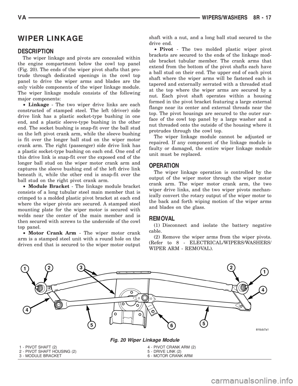
The wiper linkage and pivots are concealed within
the engine compartment below the cowl top panel
(Fig. 20). The ends of the wiper pivot shafts that pro-
trude through dedicated openings in the cowl top
panel to drive the wiper arms and blades are the
only visible components of the wiper linkage module.
The wiper linkage module consists of the following
major components:
²Linkage- The two wiper drive links are each
constructed of stamped steel. The left (driver) side
drive link has a plastic socket-type bushing in one
end, and a plastic sleeve-type bushing in the other
end. The socket bushing is snap-fit over the ball stud
on the left pivot crank arm, while the sleeve bushing
is fit over the longer ball stud on the wiper motor
crank arm. The right (passenger) side drive link has
a plastic socket-type bushing on each end. One end of
this drive link is snap-fit over the exposed end of the
longer ball stud on the wiper motor crank arm and
captures the sleeve bushing end of the left drive link
beneath it, while the other end is snap-fit over the
ball stud on the right pivot crank arm.
²Module Bracket- The linkage module bracket
consists of a long tubular steel main member that is
crimped to a molded plastic pivot bracket at each end
where the wiper pivots are secured. A stamped steel
mounting plate for the wiper motor is secured with
welds near the center of the main member and is
then secured with screws to the underside of the cowl
top panel.
²Motor Crank Arm- The wiper motor crank
arm is a stamped steel unit with a round hole on the
driven end that is secured to the wiper motor outputshaft with a nut, and a long ball stud secured to the
drive end.
²Pivot- The two molded plastic wiper pivot
brackets are secured to the ends of the linkage mod-
ule bracket tubular member. The crank arms that
extend from the bottom of the pivot shafts each have
a ball stud on their end. The upper end of each pivot
shaft where the wiper arms will be fastened each is
tapered and externally serrated with a threaded stud
at the top where the wiper arms are secured by a
nut. Each pivot shaft operates within a housing
formed in the pivot bracket featuring a large external
flange near its center and external threads near the
top. The pivot housings are secured to the outer sur-
face of the cowl top panel by a large washer and a
nut threaded onto the outside of the housing where it
protrudes through the cowl top.
The wiper linkage module cannot be adjusted or
repaired. If any component of the linkage module is
faulty or damaged, the entire wiper linkage module
unit must be replaced.
OPERATION
The wiper linkage operation is controlled by the
output of the wiper motor through the wiper motor
crank arm. The wiper motor crank arm, the two
wiper drive links, and the two wiper pivots mechan-
ically convert the rotary output of the wiper motor to
the back and forth wiping motion of the wiper arms
and blades on the glass.
REMOVAL
(1) Disconnect and isolate the battery negative
cable.
(2) Remove the wiper arms from the wiper pivots.
(Refer to 8 - ELECTRICAL/WIPERS/WASHERS/
WIPER ARM - REMOVAL).
Fig. 20 Wiper Linkage Module
1 - PIVOT SHAFT (2) 4 - PIVOT CRANK ARM (2)
2 - PIVOT SHAFT HOUSING (2) 5 - DRIVE LINK (2)
3 - MODULE BRACKET 6 - MOTOR CRANK ARM
VAWIPERS/WASHERS 8R - 17
Page 316 of 1232
INSTALLATION
(1) Select a wire from the terminal repair kit that
best matches the color and gage of the wire being
repaired.
(2) Cut the repair wire to the proper length and
remove one±half (1/2) inch of insulation.
(3) Splice the repair wire to the wire harness (see
wire splicing procedure).
(4) Insert the repaired wire into the connector.
(5) Install the connector locking wedge, if required,
and reconnect the connector to its mating half/compo-
nent.
(6) Re-tape the wire harness starting at 1±1/2
inches behind the connector and 2 inches past the
repair.
(7) Connect battery and test all affected systems.
WIRE
STANDARD PROCEDURE - WIRE SPLICING
When splicing a wire, it is important that the cor-
rect gage be used as shown in the wiring diagrams.
(1) Remove one-half (1/2) inch of insulation from
each wire that needs to be spliced.
(2) Place a piece of adhesive lined heat shrink tub-
ing on one side of the wire. Make sure the tubing will
be long enough to cover and seal the entire repair
area.
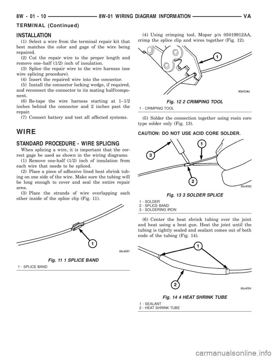
(3) Place the strands of wire overlapping each
other inside of the splice clip (Fig. 11).(4) Using crimping tool, Mopar p/n 05019912AA,
crimp the splice clip and wires together (Fig. 12).
(5) Solder the connection together using rosin core
type solder only (Fig. 13).
CAUTION: DO NOT USE ACID CORE SOLDER.
(6) Center the heat shrink tubing over the joint
and heat using a heat gun. Heat the joint until the
tubing is tightly sealed and sealant comes out of both
ends of the tubing (Fig. 14).
Fig. 11 1 SPLICE BAND
1 - SPLICE BAND
Fig. 12 2 CRIMPING TOOL
1 - CRIMPING TOOL
Fig. 13 3 SOLDER SPLICE
1 - SOLDER
2 - SPLICE BAND
3 - SOLDERING IRON
Fig. 14 4 HEAT SHRINK TUBE
1 - SEALANT
2 - HEAT SHRINK TUBE
8W - 01 - 10 8W-01 WIRING DIAGRAM INFORMATIONVA
TERMINAL (Continued)
Page 734 of 1232
OPERATION
The cigar lighter consists of two major components:
a knob and heating element unit, and the cigar
lighter base or receptacle shell. The receptacle shell
is connected to ground, and an insulated contact in
the bottom of the shell is connected to battery cur-
rent. The cigar lighter receives battery voltage from a
fuse in the fuseblock only when the ignition switch is
in the Accessory or On positions.
The knob and heating element are encased within
a spring-loaded housing, which also features a sliding
protective heat shield. When the heating element is
inserted in the receptacle shell, the heating element
resistor coil is grounded through its housing to the
receptacle shell. If the cigar lighter knob is pushed
inward, the heat shield slides up toward the knob
exposing the heating element.
Two small spring-clip retainers are located on
either side of the insulated contact inside the bottom
of the receptacle shell. These clips engage and hold
the heating element against the insulated contact
long enough for the resistor coil to heat up and glow.
When the resistor coil becomes sufficiently heated,
excess heat radiates from the heating element caus-
ing the spring-clips to expand. Once the spring-clips
expand far enough to release the heating element,
the spring-loaded housing forces the knob and heat-
ing element to pop back outward to their relaxed
position. When the cigar lighter knob and element
are pulled out of the receptacle shell, the protective
heat shield slides downward on the housing so that
the heating element is recessed and shielded around
its circumference for safety.
DIAGNOSIS AND TESTING - CIGAR LIGHTER
OUTLET
For cigar lighter outlet diagnosis and testing pro-
cedures (Refer to 8 - ELECTRICAL/POWER DISTRI-
BUTION/POWER OUTLET - DIAGNOSIS AND
TESTING)
REMOVAL
For cigar lighter outlet removal procedure (Refer to
8 - ELECTRICAL/POWER DISTRIBUTION/POWER
OUTLET - REMOVAL).
CIRCUIT BREAKER
DESCRIPTION
Automatic resetting circuit breakers are used to
protect the power window voltage supply circuits.
These circuit breakers can protect the systems from a
short circuit, or from an overload condition caused by
an obstructed or stuck power window regulator or
switch.The circuit breaker cannot be repaired and, if
faulty or damaged, it must be replaced.
OPERATION
The circuit breaker contains a bi-metal strip sand-
wiched between two contacts forming the connection
in the circuit. An overload condition causes the
bi-metal strip to heat and bend to the open position,
disconnecting current flow to the circuit. Then as the
system overload or short circuit is removed, the
bi-metal strip cools, re-establishing contact to allow
current flow to the circuit.
DIAGNOSIS AND TESTING - CIRCUIT BREAKER
For complete circuit descriptions and diagrams,
refer toWiring.
(1) Locate the correct circuit breaker in the fuse-
block. Pull out the circuit breaker slightly, but be cer-
tain that the circuit breaker terminals still contact
the terminals in the fuseblock cavities.
(2) Connect the negative lead of a 12-volt DC volt-
meter to a good ground.
(3) With the voltmeter positive lead, check both
terminals of the circuit breaker for battery voltage.
If only one terminal has battery voltage, the circuit
breaker is faulty and must be replaced. If neither ter-
minal has battery voltage, repair the open circuit
from the Power Distribution Center as required.
FUSE BLOCK #1
DESCRIPTION
An electrical fuse block is concealed under the
driver side steering column. The fuse block serves to
distribute electrical current to many of the electrical
systems in the vehicle. The fuse block contains blade-
type mini fuses, relays and micro processors that
enable automatic control of some of the power distri-
bution circuits throughout the vehicle.
The molded plastic fuse block housing has an inte-
gral mounting bracket that is secured with screws to
the steering column. A finger recess is molded into
the cover for easy removal. A fuse layout map is
molded onto the back side of the cover to ensure
proper fuse identification.
The fuse block cannot be repaired, if the fuse block
is faulty or damaged or if any internal circuit is
faulty or damaged, the entire fuse block must be
replaced.
OPERATION
All of the circuits entering and leaving the fuse
block do so through the instrument panel wire har-
ness. Internal connection of all of the fuse block cir-
cuits is accomplished by an intricate combination of
8W - 97 - 2 8W-97 POWER DISTRIBUTIONVA
CIGAR LIGHTER OUTLET (Continued)
Page 735 of 1232
hard wiring and bus bars. Internal relays and micro
processors allow the vehicle electronics to control
some of the power distribution circuits throughout
the vehicle. Refer to the Wiring section for complete
circuit diagrams.
REMOVAL
(1) Disconnect and isolate the negative battery
cable.
(2) Remove fuse block cover by rotating locking
screw 90É.
(3) Remove the steering column cover. Refer to the
Body section for the procedure.
(4) Unscrew fuse block connections and disconnect
all electrical connectors from the fuse block.
(5) Remove the fuse block from the steering col-
umn.
INSTALLATION
(1) Position the fuse block in the steering column.
(2) Install fuse block connections and connect all
electrical connectors on the fuse block.
(3) Install the steering column cover. Refer to the
Body section for the procedure.
(4) Install fuse block cover by rotating locking
screw 90É.
(5) Connect the negative battery cable.
(6) Set time and radio stations.
FUSE BLOCK #2
DESCRIPTION
An electrical fuse block is concealed under the
driver side front seat. The fuse block serves to dis-
tribute electrical current to many of the electrical
systems in the vehicle. The fuse block houses blade-
type mini fuses, blade-type automatic resetting cir-
cuit breakers and International Standards
Organization relays. Additional provisions are avail-
able in the fuse block for additional fuses and ISO
relays.
The molded plastic fuse block housing has an inte-
gral mounting bracket that is secured with screws to
the seat base. The driver side seat base also has a
snap-fit fuse access panel that can be removed for
service of the fuses and the relays. A finger recess is
molded into one end for easy removal. A fuse layout
map is molded onto the back side of the panel to
ensure proper fuse identification.
The fuse block is integral to the body wire harness.
If any internal circuit or the fuse block housing is
faulty or damaged, the entire fuse block and body
wire harness unit must be replaced.
OPERATION
All of the circuits entering and leaving the fuse
block do so through the body wire harness. Internal
connection of all of the fuse block circuits is accom-
plished by an intricate combination of hard wiring
and bus bars.
POWER DISTRIBUTION
CENTER
DESCRIPTION
All of the electrical current distributed throughout
this vehicle is directed through the Power Distribu-
tion Center (PDC). The molded plastic PDC housing
is located in the left front corner of the engine com-
partment, on the battery positive cable. The PDC
housing has a molded plastic cover that slides over
the PDC housing. The PDC cover is easily opened or
removed for service access.
The PDC unit cannot be repaired and is only ser-
viced as a unit with the headlamp and dash wire
harness. If the internal circuits or the PDC housing
are faulty or damaged, the headlamp and dash wire
harness unit must be replaced.
OPERATION
All of the current from the battery and the gener-
ator output enters the PDC through the positive bat-
tery cable. The PDC cover is removed to access the
battery and generator output connection B(+) termi-
nal studs. Internal connection of all of the PDC cir-
cuits is accomplished by an intricate combination of
hard wiring and bus bars. Refer to Wiring Diagrams
for the location of complete PDC circuit diagrams.
POWER OUTLET
DESCRIPTION
The power outlet is installed in the instrument
panel accessory switch plate, which is located near
the center of the instrument panel. The power outlet
base is secured by a snap fit within the instrument
panel. A plastic protective cap snaps over the power
outlet base when the power outlet is not being used.
While the power outlet is very similar to a cigar
lighter base unit, it does not include the two small
spring-clip retainers inside the bottom of the recepta-
cle shell that are used to secure the cigar lighter
heating element to the insulated contact.
The power outlet receptacle unit are available for
service. The power outlet receptacle cannot be
repaired and, if faulty or damaged, it must be
replaced.
VA8W-97 POWER DISTRIBUTION 8W - 97 - 3
FUSE BLOCK #1 (Continued)
Page 813 of 1232
CATALYTIC CONVERTER
REMOVAL
(1) Raise and support the vehicle.
(2) Saturate the clamp nuts with heat valve lubri-
cant. Allow 5 minutes for penetration. Remove the
rear clamp. (Fig. 1)
(3) Saturate the clamp nuts with heat valve lubri-
cant. Allow 5 minutes for penetration. Remove the
front clamp.
(4) Remove the cataylic converter and muffler
assembly from the isolators.
(5) Seperat the cataylic converter and muffler
assembly from the tailpipe and the exhaust pipe.
(6) Remove the cataylic converter and muffler
assembly and isolators from the vehicle.
(7) Remove the bolt, nut and front isolator from
the cataylic converter and muffler assembly.
(8) Remove the rear isolator from the cataylic con-
verter and muffler assembly.
(9)
INSTALLATION
(1) Install bolt, front isolator and nut (Fig. 1).
(2) Install rear insulator onto the cataylic con-
verter and muffler assembly
(3) Position the cataylic conveter and muffler
assembly into the exhaust pipe and tailpipe until
alignment tab is inserted into the alignment slot.
(4) Install the front and rear insulators.
(5) Install the real clamp.
(6) Install the front clamp.
(7) Lower vehicle.
(8) Start the vehicle and inspect for exhaust leaks.
Repair exhaust leaks as necessary.
(9) Check the exhaust system for contact with the
body panels. Make necessary adjustments, if neces-
sary.
EXHAUST PIPE
REMOVAL
(1) Raise and support the vehicle.
(2) Saturate the clamp nuts with heat valve lubri-
cant. Allow 5 minutes for penetration. Remove the
front and rear clamp (Fig. 1).
(3) Remove the mounting bracket nuts.
(4) Remove the exhaust pipe.
INSTALLATION
(1) Position the exhaust pipe into the exhaust pipe
into the cataylic converter and muffler assembly
until alignment tab is inserted into the alignment
slot.
(2) Install mounting bracket and nuts (Fig. 1).(3) Install clamp.
(4) Lower the vehicle.
(5) Start the vehicle and inspect for exhaust leaks.
Repair exhaust leaks as necessary.
(6) Check the exhaust system for contact with the
body panels. Make necessary adjustments, if neces-
sary.
TAILPIPE
REMOVAL
(1) Raise and support the vehicle.
(2) Saturate the clamp nuts with heat valve lubri-
cant. Allow 5 minutes for penetration (Fig. 1).
(3) Remove the clamp.
(4) Remove the tailpipe and insulator form the
vehicle
(5) Remove the insulator from the tailpipe.
INSTALLATION
(1) Position the tail pipe into the cataylic converter
and muffler assembly until alignment tab is inserted
into the alignment slot.
(2) Install the insulator.
(3) Install the clamp.
(4) Lower the vehicle.
(5) Start the vehicle and inspect for exhaust leaks.
Repair exhaust leaks as necessary.
(6) Check the exhaust system for contact with the
body panels. Make necessary adjustments, if neces-
sary.
TURBOCHARGER SYSTEM
DESCRIPTION
CAUTION: The turbocharger is a performance part
and must not be tampered with. The boost pressure
bracket is an integral part of the turbocharger. Tam-
pering with the boost pressure components can
reduce durability by increasing cylinder pressure
and thermal loading due to incorrect inlet and
exhaust manifold pressure. Poor fuel economy and
failure to meet regulatory emissions laws may
result. Increasing the turbocharger boost WILL NOT
increase engine power.
The turbocharger used on this vehicle is of the
variable turbine type. These turbochargers use the
entire exhaust energy to boost efficiency of the turbo-
charger and the engine.
The advantages of a turbocharger with variable
turbine geometry are:
²Higher charge pressure already in the lower and
in upper engine speed ranges.
VAEXHAUST SYSTEM 11 - 3
Page 1030 of 1232
TIRES
DESCRIPTION
DESCRIPTION - TIRES
Tires are designed and engineered for each specific
vehicle. They provide the best overall performance
for normal operation. The ride and handling charac-
teristics match the vehicle's requirements. With
proper care they will give excellent reliability, trac-
tion, skid resistance, and tread life.
Driving habits have more effect on tire life than
any other factor. Careful drivers will obtain in most
cases, much greater mileage than severe use or care-
less drivers. A few of the driving habits which will
shorten the life of any tire are:
²Rapid acceleration
²Severe brake applications
²High speed driving
²Excessive speeds on turns
²Striking curbs and other obstacles
Radial-ply tires are more prone to irregular tread
wear. It is important to follow the tire rotation inter-
val shown in the section on Tire Rotation, (Refer to
22 - TIRES/WHEELS - STANDARD PROCEDURE).
This will help to achieve a greater tread life.
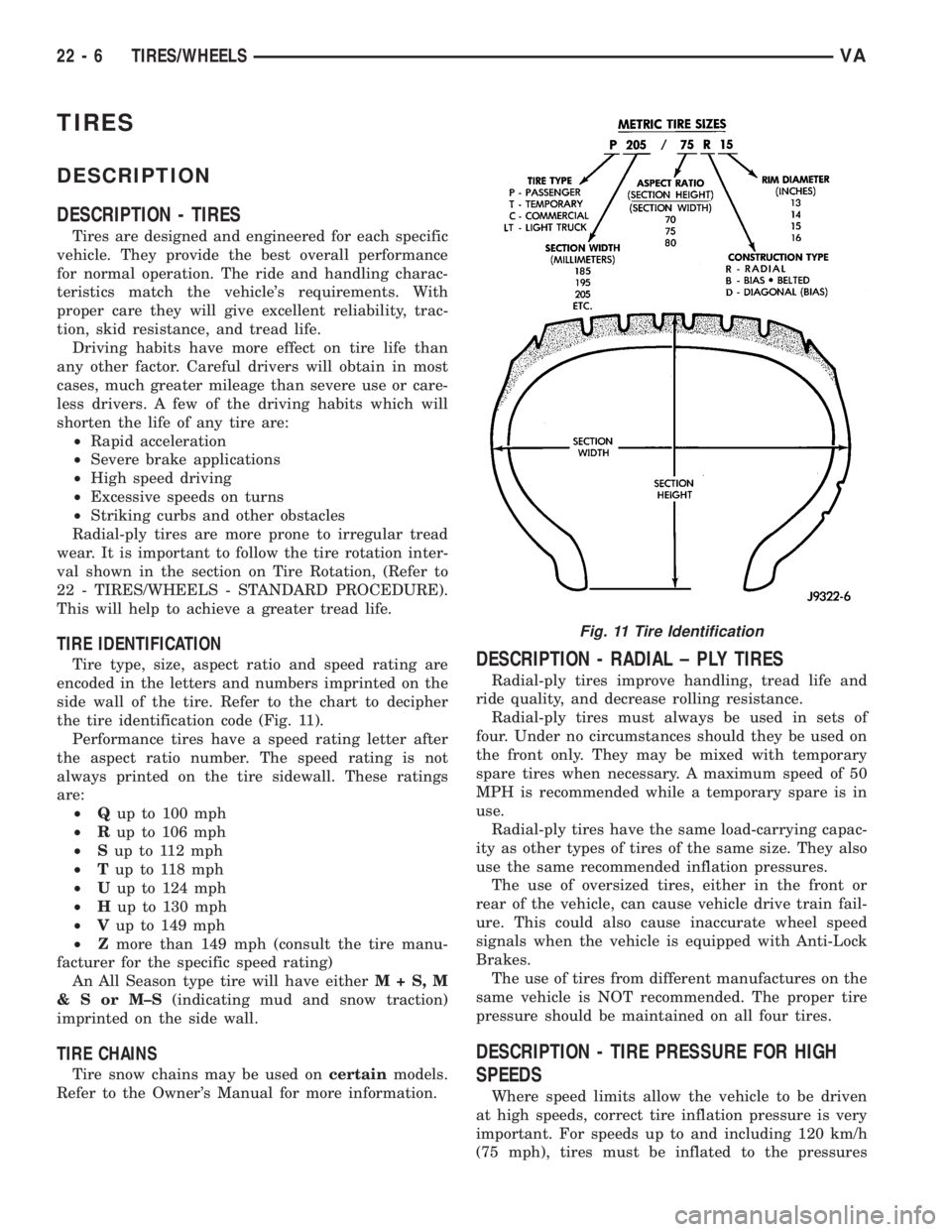
TIRE IDENTIFICATION
Tire type, size, aspect ratio and speed rating are
encoded in the letters and numbers imprinted on the
side wall of the tire. Refer to the chart to decipher
the tire identification code (Fig. 11).
Performance tires have a speed rating letter after
the aspect ratio number. The speed rating is not
always printed on the tire sidewall. These ratings
are:
²Qup to 100 mph
²Rup to 106 mph
²Sup to 112 mph
²Tup to 118 mph
²Uup to 124 mph
²Hup to 130 mph
²Vup to 149 mph
²Zmore than 149 mph (consult the tire manu-
facturer for the specific speed rating)
An All Season type tire will have eitherM+S,M
&SorM±S(indicating mud and snow traction)
imprinted on the side wall.
TIRE CHAINS
Tire snow chains may be used oncertainmodels.
Refer to the Owner's Manual for more information.
DESCRIPTION - RADIAL ± PLY TIRES
Radial-ply tires improve handling, tread life and
ride quality, and decrease rolling resistance.
Radial-ply tires must always be used in sets of
four. Under no circumstances should they be used on
the front only. They may be mixed with temporary
spare tires when necessary. A maximum speed of 50
MPH is recommended while a temporary spare is in
use.
Radial-ply tires have the same load-carrying capac-
ity as other types of tires of the same size. They also
use the same recommended inflation pressures.
The use of oversized tires, either in the front or
rear of the vehicle, can cause vehicle drive train fail-
ure. This could also cause inaccurate wheel speed
signals when the vehicle is equipped with Anti-Lock
Brakes.
The use of tires from different manufactures on the
same vehicle is NOT recommended. The proper tire
pressure should be maintained on all four tires.
DESCRIPTION - TIRE PRESSURE FOR HIGH
SPEEDS
Where speed limits allow the vehicle to be driven
at high speeds, correct tire inflation pressure is very
important. For speeds up to and including 120 km/h
(75 mph), tires must be inflated to the pressures
Fig. 11 Tire Identification
22 - 6 TIRES/WHEELSVA