Page 796 of 969
190SI-01
- STARTING & CHARGINGCHARGING SYSTEM (3MZ-FE)
19-15
2347 Author�: Date�:
2005 LEXUS ES330 REPAIR MANUAL (RM1124U)
CHARGING SYSTEM (3MZ-FE)
PRECAUTION
1. SYSTEM INITIALIZATION
NOTICE:
When disconnecting the negative (-) battery terminal, initialize the following systems after the termi-
nal is reconnected.
System NameSee Page
Power Window Control System05-1470
Sliding Roof System74-8
2. Check that the battery cables are connected to the correct terminals.
3. Disconnect the battery cables if a quick charge is given to the battery.
4. Do not perform tests with a high voltage insulation resistance tester.
5. Never disconnect the battery while the engine is running.
6. Check that the charging cable is tightened on terminal B of the generator and the fuse box.
7. Do not check whether the alternator generates current or not with terminal F connected to the
other terminals.
Page 798 of 969

A01259
A01260
A82941
White Red Blue
B00543
- STARTING & CHARGINGCHARGING SYSTEM (3MZ-FE)
19-17
2349 Author�: Date�:
2005 LEXUS ES330 REPAIR MANUAL (RM1124U)
(b) Check the battery specific gravity.
(1) Check the specific gravity of each cell.
Standard specific gravity: 1.25 to 1.29 at 20�C (68�F)
If the specific gravity is less than specification, charge the bat-
tery.
(c) Check the battery voltage.
(1) If it has been less than 20 minutes since you
stopped driving the vehicle or since the engine was
stopped, turn the ignition switch and electrical sys-
tems (headlight, blower motor, rear defogger etc.)
to the ON position for 60 seconds. This will remove
the surface charge on the battery.
(2) Turn the ignition switch and electrical systems OFF.
(3) Using a voltmeter, measure the battery voltage be-
tween the negative (-) and positive (+) terminals of
the battery.
Standard voltage: 12.5 to 12.9 V at 20�C (68�F)
If the voltage is less than the specification, charge the battery.
(d) Check the indicator as shown in the illustration.
HINT:
�Blue: OK
�White: Charging Necessary
�Red: Insufficient Water
3. INSPECT BATTERY TERMINALS, FUSIBLE LINK AND FUSES
(a) Visually check the battery terminals.
(1) Check that the battery terminals are not loosened or corroded.
(b) Visually check the fusible link and fuses.
(1) Check that there is continuity of the fusible links, high current fuses and regular fuses.
4. INSPECT V-RIBBED BELT
(a) Visually check the belt for excessive wear, frayed cords,
etc.
�If any defects are found, replace the v-ribbed belt.
�Cracks on the rib side of the belt are considered ac-
ceptable.
If the belt has chunks missing from the ribs, it should
be replaced.
Page 888 of 969
Lexus Supports ASE CertificationPage 1 of 9
Title:
PRE-DELIVERY SERVICE (PDS)
INFORMATION FOR ES 330
Models:
'04 ES 330
Technical Service
Information Bulletin
August 26, 2003
PD002-03
The following items need to be performed during Pre±Delivery Service (PDS) on
2004 model year ES 330 vehicles.
�2004 model year ES 330 vehicles.
ITEM NO.SUBJECTPAGE
1D.C.C. Fuse Installation During PDS2
2Removal of Front Emergency Towing Eyelet and Installation
of Towing Eyelet Hole Cover (Performed at Port)3
3Front License Plate Mounting Bracket Installation4
4Initialization of Moon Roof5
5Initial Calibration of Compass6
6Installation of Rubber Body Plugs9
OP CODEDESCRIPTIONTIMEOFPT1T2
N/ANot Applicable to Warranty±±±±
PRE±DELIVERY SERVICE
Introduction
Applicable
Vehicles
Contents
Warranty
Information
Page 889 of 969
PRE±DELIVERY SERVICE (PDS) INFORMATION FOR ES 330 ± PD002-03 August 26, 2003
Page 2 of 9
D.C.C. FUSE INSTALLATION DURING PDS
The D.C.C. fuse has been removed at the assembly plant to reduce parasitic current
draw in transit and storage.
The removed D.C.C. fuse (30 A) is stored in the blank space of the Junction Block in
the engine compartment. The D.C.C. fuse must be reinstalled during Pre±Delivery
Service (PDS) in the dealership as shown below.
Junction Block
Install D.C.C. Fuse (30 A)
Here (Original Location)Remove This Fuse
NOTE:
�Removing the D.C.C. fuse cuts off power sources relating to the Dome, ECU±B and
RAD No. 1 fuses.
�If the vehicle is stored in the dealership for a long period of time after PDS,
disconnect the negative battery terminal to prevent battery discharge. Refer to TSIB
PG009±02 for battery maintenance information.
ITEM NO. 1:
Introduction
Installation
Procedure
Page 898 of 969

Lexus Supports ASE CertificationPage 1 of 1
Title:
DCC FUSE INSTALLATION DURING PDS
Models:
'05 ± '06 ES 330
Technical Service
Information Bulletin
August 22, 2005
PD032-05
The DCC fuse has been removed at the assembly plant to reduce parasitic current
draw in transit and storage.
�2005 ± 2006 model year ES 330 vehicles.
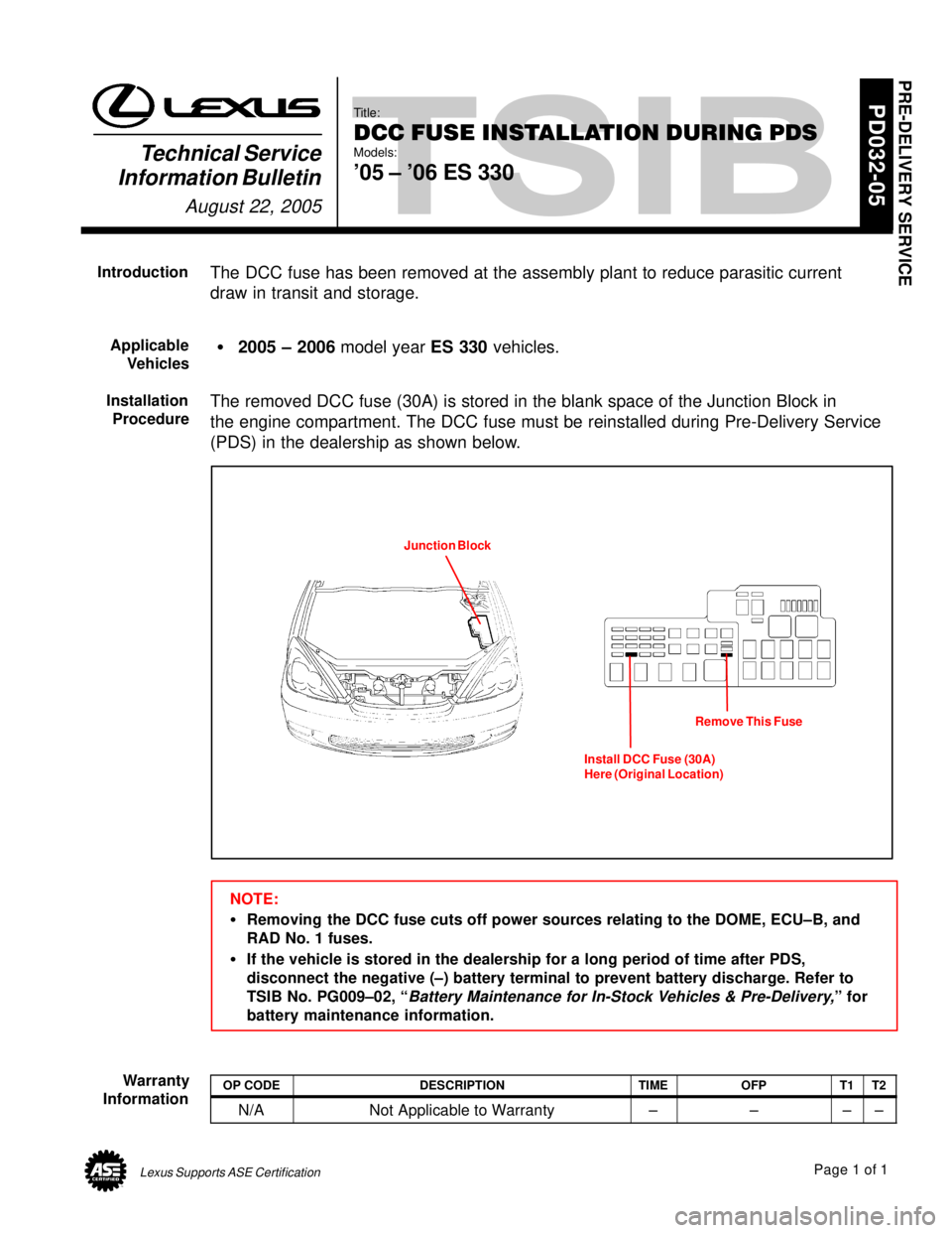
The removed DCC fuse (30A) is stored in the blank space of the Junction Block in
the engine compartment. The DCC fuse must be reinstalled during Pre-Delivery Service
(PDS) in the dealership as shown below.
Junction Block
Install DCC Fuse (30A)
Here (Original Location)Remove This Fuse
NOTE:
�Removing the DCC fuse cuts off power sources relating to the DOME, ECU±B, and
RAD No. 1 fuses.
�If the vehicle is stored in the dealership for a long period of time after PDS,
disconnect the negative (±) battery terminal to prevent battery discharge. Refer to
TSIB No. PG009±02, ª
Battery Maintenance for In-Stock Vehicles & Pre-Delivery,º for
battery maintenance information.
OP CODEDESCRIPTIONTIMEOFPT1T2
N/ANot Applicable to Warranty±±±±
PRE-DELIVERY SERVICE
Introduction
Applicable
Vehicles
Installation
Procedure
Warranty
Information
Page 917 of 969
BATTERY MAINTENANCE FOR IN±STOCK VEHICLES & PRE±DELIVERY ± PG009-02 September 12, 2002
Page 4 of 4
In addition to this new pre±delivery battery test, a monthly battery inspection is still
required for stored vehicles. If your dealership is located in an area subject to extreme
temperatures (hot or cold), periodic maintenance may need to be performed more
frequently.
To reduce parasitic battery drain for vehicles in storage for one week or more, the
negative battery cable should always be disconnected to reduce battery discharge.
When the negative battery cable is reconnected, please check and reset electrical
components such as the clock, radio, etc.
NOTE:
For your reference, the electrical system is made inoperative by removing the
appropriate fuse indicated in the Electrical Wiring Diagram. Recom-
mended
Battery
Maintenance