Page 728 of 969
F41590
51-6
- POWER STEERINGPOWER STEERING SYSTEM
2581 Author�: Date�:
(j) Disconnect the SST.
SST 09640- 10010 (09641- 01010, 09641- 01020,
09641-01030)
(k) Connect the pressure feed tube assy to the rack & pinion
power steering gear assy (See page 51-21).
(l) Bleed the power steering system.
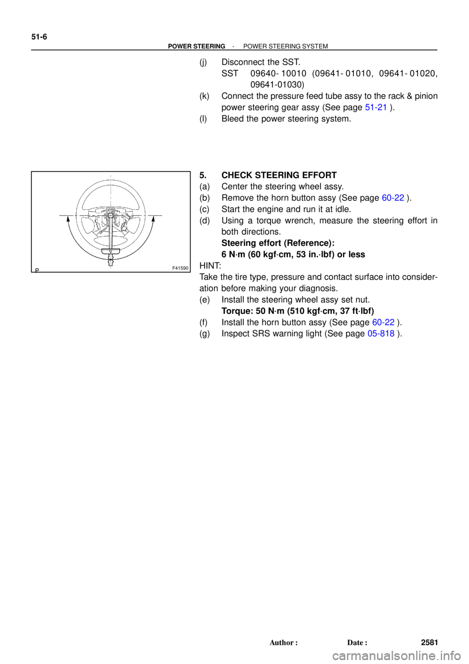
5. CHECK STEERING EFFORT
(a) Center the steering wheel assy.
(b) Remove the horn button assy (See page 60-22).
(c) Start the engine and run it at idle.
(d) Using a torque wrench, measure the steering effort in
both directions.
Steering effort (Reference):
6 N´m (60 kgf´cm, 53 in.´lbf) or less
HINT:
Take the tire type, pressure and contact surface into consider-
ation before making your diagnosis.
(e) Install the steering wheel assy set nut.
Torque: 50 N´m (510 kgf´cm, 37 ft´lbf)
(f) Install the horn button assy (See page 60-22).
(g) Inspect SRS warning light (See page 05-818).
Page 762 of 969
51-40
- POWER STEERINGRACK & PINION POWER STEERING GEAR ASSY
2615 Author�: Date�:
2005 LEXUS ES330 REPAIR MANUAL (RM1124U)
68. CONNECT TIE ROD ASSY LH
(a) Connect the tie rod assy LH with the nut.
Torque: 49 NVm (500 kgfVcm, 36 ftVlbf)
(b) Install a new cotter pin.
NOTICE:
If the holes for a new cotter pin are not aligned, tighten the nut further up 60�.
69. CONNECT TIE ROD ASSY RH
HINT:
Install the RH side by the same procedures with LH side.
70. INSTALL FRONT WHEEL
Torque: 103 NVm (1,050 kgfVcm, 76 ftVlbf)
71. BLEED POWER STEERING FLUID (See page 51-3)
72. CHECK POWERSTEERING FLUID LEAKAGE
73. INSTALL SPIRAL CABLE SUB-ASSY
(See page 50-8)
74. CENTER SPIRAL CABLE(See page 50-8)
75. INSTALL STEERING WHEEL ASSY
(See page 50-8)
76. INSTALL HORN BUTTON ASSY
(See page 60-22)
77. INSPECT AND ADJUST FRONT WHEEL ALIGNMENT(See page 26-5)
78. INSPECT STEERING WHEEL CENTER POINT
79. INSPECT SRS WARNING LIGHT(See page 05-826)
Page 775 of 969

20. STABILIZE SUSPENSION
(a) Jack up the rear axle carrier,")
C91813
C82996
C82997
- REAR SUSPENSIONREAR SUSPENSION ARM ASSY NO.1 LH
27-13
2395 Author�: Date�:
2005 LEXUS ES330 REPAIR MANUAL (RM1124U)
20. STABILIZE SUSPENSION
(a) Jack up the rear axle carrier, placing a wooden block be-
tween them. Apply load to the suspension so that the
installed bolt of the suspension arm assy No. 1 (vehicle
side) is horizontally aligned with the center of the rear axle
hub.
21. FULLY TIGHTEN REAR SUSPENSION ARM ASSY
NO.1 LH
(a) Fully tighten the bolt.
Torque: 100 NVm (1,020 kgfVcm, 74 ftVlbf)
HINT:
While fixing the nut, turn the bolt.
22. FULLY TIGHTEN REAR SUSPENSION ARM ASSY NO.1 RH
HINT:
Fully tighten the RH side by the procedures with the LH side.
23. FULLY TIGHTEN REAR SUSPENSION ARM ASSY
NO.2 LH
(a) Fully tighten the bolt.
Torque: 100 NVm (1,020 kgfVcm, 74 ftVlbf)
HINT:
While fixing the nut, turn the bolt.
24. FULLY TIGHTEN REAR SUSPENSION ARM ASSY NO.2 RH
HINT:
Fully tighten the RH side by the procedures with the LH side.
25. FULLY TIGHTEN STRUT ROD ASSY REAR (See page 27-18)
26. INSTALL STABILIZER BAR REAR (See page 27-16)
27. INSTALL EXHAUST PIPE ASSY CENTER (See page 15-2)
28. INSTALL REAR WHEEL
Torque: 103 NVm (1,050 kgfVcm, 76 ftVlbf)
29. INSPECT REAR WHEEL ALIGNMENT (See page 27-3)
30. HEADLIGHT AIM ONLY (See page 65-15)
Page 777 of 969

- REAR SUSPENSIONREAR SUSPENSION ARM ASSY NO.2 LH
27-15
2397 Author�: Date�:
2005 LEXUS ES330 REPAIR MANUAL (RM1124U)
(b) Set the suspension arm in the position in the illustr")
B53747
38 mm (1.5 in.)
- REAR SUSPENSIONREAR SUSPENSION ARM ASSY NO.2 LH
27-15
2397 Author�: Date�:
2005 LEXUS ES330 REPAIR MANUAL (RM1124U)
(b) Set the suspension arm in the position in the illustration
and fully tighten the bolt.
Torque: 100 NVm (1,020 kgfVcm, 74 ftVlbf)
13. INSTALL REAR SUSPENSION MEMBER SUB-ASSY (See page 27-10)
14. TEMPORARILY TIGHTEN REAR SUSPENSION ARM ASSY NO.1 LH (See page 27-10)
15. TEMPORARILY TIGHTEN REAR SUSPENSION ARM ASSY NO.1 RH
HINT:
Temporarily tighten the RH side by the procedures with the LH side.
16. TEMPORARILY TIGHTEN REAR SUSPENSION ARM ASSY NO.2 LH (See page 27-10)
17. TEMPORARILY TIGHTEN REAR SUSPENSION ARM ASSY NO.2 RH
HINT:
Temporarily tighten the RH side by the procedures with the LH side.
18. TEMPORARILY TIGHTEN STRUT ROD ASSY REAR (See page 27-18)
19. CONNECT HEIGHT CONTROL SENSOR SUB-ASSY REAR RH (See page 65-33)
20. STABILIZE SUSPENSION (See page 27-10)
21. FULLY TIGHTEN REAR SUSPENSION ARM ASSY NO.1 LH (See page 27-10)
22. FULLY TIGHTEN REAR SUSPENSION ARM ASSY NO.1 RH
HINT:
Fully tighten the RH side by the procedures with the LH side.
23. FULLY TIGHTEN REAR SUSPENSION ARM ASSY NO.2 LH (See page 27-10)
24. FULLY TIGHTEN REAR SUSPENSION ARM ASSY NO.2 RH
HINT:
Fully tighten the RH side by the procedures with the LH side.
25. FULLY TIGHTEN STRUT ROD ASSY REAR (See page 27-18)
26. INSTALL STABILIZER BAR REAR (See page 27-16)
27. INSTALL EXHAUST PIPE ASSY CENTER (See page 15-2)
28. INSTALL REAR WHEEL
Torque: 103 NVm (1,050 kgfVcm, 76 ftVlbf)
29. INSPECT REAR WHEEL ALIGNMENT (See page 27-3)
30. HEADLIGHT AIM ONLY (See page 65-15)
Page 797 of 969

2348 Author�: Date�:
2005 LEXUS ES330 REPAIR MANUAL (RM1124U)
ON-VEHICLE INSPECTION
1. INSPECT BATTERY (MAI")
190SJ-01
A01260
A82941
White Red Blue 19-16
- STARTING & CHARGINGCHARGING SYSTEM (3MZ-FE)
2348 Author�: Date�:
2005 LEXUS ES330 REPAIR MANUAL (RM1124U)
ON-VEHICLE INSPECTION
1. INSPECT BATTERY (MAINTENANCE- FREE BAT-
TERY)
(a) Check the battery electrolyte level.
(1) Check the electrolyte quantity of each cell.
If the electrolyte quantity is below the recommended amount,
replace the battery.
(b) Check the battery voltage.
(1) If it has been less than 20 minutes since you
stopped driving the vehicle or since the engine was
stopped, turn the ignition switch and electrical sys-
tems (headlight, blower motor, rear defogger etc.)
to the ON position for 60 seconds. This will remove
the surface charge on the battery.
(2) Turn the ignition switch and electrical systems OFF.
(3) Using a voltmeter, measure the battery voltage be-
tween the negative (-) and positive (+) terminals of
the battery.
Standard voltage: 12.5 to 12.9 V at 20�C (68�F)
If the voltage is less than the specification, charge the battery.
(c) Check the indicator as shown in the illustration.
HINT:
�Blue: OK
�White: Charging Necessary
�Red: Insufficient Water
2. INSPECT BATTERY (EXCEPT MAINTENANCE-FREE
BATTERY)
(a) Check the battery electrolyte level.
(1) Check the electrolyte quantity of each cell.
If the electrolyte quantity is below the recommended amount,
add distilled water.
Page 798 of 969

19-17
2349 Author�: Date�:
2005 LEXUS ES330 REPAIR MANUAL (RM1124U)
(b) Check the battery specific gravity.
(")
A01259
A01260
A82941
White Red Blue
B00543
- STARTING & CHARGINGCHARGING SYSTEM (3MZ-FE)
19-17
2349 Author�: Date�:
2005 LEXUS ES330 REPAIR MANUAL (RM1124U)
(b) Check the battery specific gravity.
(1) Check the specific gravity of each cell.
Standard specific gravity: 1.25 to 1.29 at 20�C (68�F)
If the specific gravity is less than specification, charge the bat-
tery.
(c) Check the battery voltage.
(1) If it has been less than 20 minutes since you
stopped driving the vehicle or since the engine was
stopped, turn the ignition switch and electrical sys-
tems (headlight, blower motor, rear defogger etc.)
to the ON position for 60 seconds. This will remove
the surface charge on the battery.
(2) Turn the ignition switch and electrical systems OFF.
(3) Using a voltmeter, measure the battery voltage be-
tween the negative (-) and positive (+) terminals of
the battery.
Standard voltage: 12.5 to 12.9 V at 20�C (68�F)
If the voltage is less than the specification, charge the battery.
(d) Check the indicator as shown in the illustration.
HINT:
�Blue: OK
�White: Charging Necessary
�Red: Insufficient Water
3. INSPECT BATTERY TERMINALS, FUSIBLE LINK AND FUSES
(a) Visually check the battery terminals.
(1) Check that the battery terminals are not loosened or corroded.
(b) Visually check the fusible link and fuses.
(1) Check that there is continuity of the fusible links, high current fuses and regular fuses.
4. INSPECT V-RIBBED BELT
(a) Visually check the belt for excessive wear, frayed cords,
etc.
�If any defects are found, replace the v-ribbed belt.
�Cracks on the rib side of the belt are considered ac-
ceptable.
If the belt has chunks missing from the ribs, it should
be replaced.
Page 799 of 969

2350 Author�: Date�:
2005 LEXUS ES330 REPAIR MANUAL (RM1124U)
(b")
B00540
A88419
Disconnect Wire
from Terminal B
Generator Voltmeter
BatteryAmmeter 19-18
- STARTING & CHARGINGCHARGING SYSTEM (3MZ-FE)
2350 Author�: Date�:
2005 LEXUS ES330 REPAIR MANUAL (RM1124U)
(b) Check that the belt fits properly in the ribbed grooves.
Confirm that the belt has not slipped out of the groove on the
bottom of the pulley by hand.
5. INSPECT GENERATOR WIRING
(a) Visually check the generator wiring.
(1) Check that the wiring is in good condition.
6. INSPECT ABNORMAL NOISES
(a) Listen to abnormal noises from generator.
(1) Check that no abnormal noise is heard from the generator while the engine is running.
7. INSPECT CHARGE WARNING LIGHT CIRCUIT
(a) Turn the ignition switch ON. Check that the charge warning light comes on.
(b) Start the engine, then check that the light goes off.
If the light does not operate as specified, troubleshoot the charge warning light circuit.
8. INSPECT CHARGING CIRCUIT WITHOUT LOAD
(a) If a tester is not available, connect a voltmeter to the
charging circuit as follows.
(1) Disconnect the wire from terminal B of the genera-
tor, then connect it to the negative (-) lead of the
ammeter.
(2) Connect the positive (+) lead of the ammeter to ter-
minal B of the generator.
(3) Connect the positive (+) lead of the voltmeter to ter-
minal B of the generator.
(4) Ground the negative (-) lead of the voltmeter.
(b) Check the charging circuit.
(1) Keep the engine speed at 2,000 rpm, then check
the reading on the ammeter and voltmeter.
Standard amperage: 10 A or less
Standard voltage: 13.2 to 14.8 V
9. INSPECT CHARGING CIRCUIT WITH LOAD
(a) With the engine running at 2,000 rpm, turn the high beam headlights ON and turn the heater blower
switch to the ºHIº position.
(b) Check the reading on the ammeter.
Standard amperage: 30 A or more
�If the ammeter reading is less than the standard amperage, repair the generator.
�If the battery is fully charged, the indication will sometimes be less than the standard amperage.
Page 823 of 969
50-14
- STEERING COLUMNSTEERING COLUMN ASSY
2575 Author�: Date�:
51. INSTALL STEERING WHEEL ASSY
(a) Align the matchmarks on the steering wheel assy and steering main shaft assy.
(b) Install the steering wheel assy set nut.
Torque: 50 NVm (510 kgfVcm, 37 ftVlbf)
52. INSPECT HORN BUTTON ASSY(See page 60-22)
53. INSTALL HORN BUTTON ASSY(See page 60-22)
54. INSTALL STEERING PAD SWITCH
(a) Connect the connector.
(b) Install the steering pad switch with the 2 screws.
55. INSTALL CONNECTOR COVER
56. INSTALL STEERING WHEEL COVER LOWER NO.2
57. INSPECT SRS WARNING LIGHT(See page 05-818)