Page 136 of 969
D03569
D03629
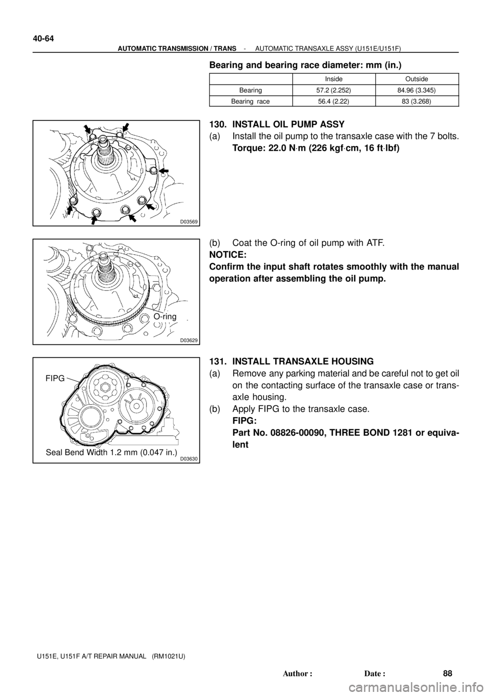
O-ring
D03630Seal Bend Width 1.2 mm (0.047 in.) FIPG
40-64
- AUTOMATIC TRANSMISSION / TRANSAUTOMATIC TRANSAXLE ASSY (U151E/U151F)
88 Author�: Date�:
U151E, U151F A/T REPAIR MANUAL (RM1021U)
Bearing and bearing race diameter: mm (in.)
InsideOutside
Bearing57.2 (2.252)84.96 (3.345)
Bearing race56.4 (2.22)83 (3.268)
130. INSTALL OIL PUMP ASSY
(a) Install the oil pump to the transaxle case with the 7 bolts.
Torque: 22.0 NVm (226 kgfVcm, 16 ftVlbf)
(b) Coat the O-ring of oil pump with ATF.
NOTICE:
Confirm the input shaft rotates smoothly with the manual
operation after assembling the oil pump.
131. INSTALL TRANSAXLE HOUSING
(a) Remove any parking material and be careful not to get oil
on the contacting surface of the transaxle case or trans-
axle housing.
(b) Apply FIPG to the transaxle case.
FIPG:
Part No. 08826-00090, THREE BOND 1281 or equiva-
lent
Page 137 of 969

40-65
89 Author�: Date�:
U151E, U151F A/T REPAIR MANUAL (RM1")
D25608
C
C
CAB2WD:
4WD:
B
D
C CC
CB
B
A
A
D08091
D03631
D26468
SST
- AUTOMATIC TRANSMISSION / TRANSAUTOMATIC TRANSAXLE ASSY (U151E/U151F)
40-65
89 Author�: Date�:
U151E, U151F A/T REPAIR MANUAL (RM1021U)
(c) Install the transaxle housing and 16 bolts to the transaxle
case.
Torque:
Bolt A: 25 NVm (255 kgfVcm, 18 ftVlbf)
Bolt B: 33 NVm (337 kgfVcm, 24 ftVlbf)
Bolt C: 29 NVm (295 kgfVcm, 21 ftVlbf)
Bolt D: 22 NVm (226 kgfVcm, 16.0 ftVlbf)
HINT:
Apply seal packing or equivalent to the bolt A and D.
Seal packing:
THREE BOND 2403 or equivalent
Bolt length:
Bolt A: 50 mm (1.969 in.)
Bolt B: 50 mm (1.969 in.)
Bolt C: 42 mm (1.654 in.)
Bolt D: 72 mm (2.835 in.)
NOTICE:
Because the bolt A is a seal bolt, apply the seal packing to
new bolts and tighten them within 10 minutes after applica-
tion.
132. INSPECT INPUT SHAFT ENDPLAY
(a) Using a dial indicator, measure the input shaft end play.
End play: 0.262 - 1.249 mm (0.0100 - 0.0494 in.)
133. FIX AUTOMATIC TRANSAXLE ASSY
(a) Fix the transaxle assy.
134. INSTALL MANUAL VALVE LEVER SHAFT OIL SEAL
(a) Coat a new oil seal with MP grease.
(b) Install the oil seal to the transaxle case.
SST 09950- 60010 (09951- 00230), 09950- 70010
(09951-07100)
Oil seal drive in depth: 0 � 0.5 mm (0 � 0.0197 in.)
Page 139 of 969

40-67
91 Author�: Date�:
U151E, U151F A/T REPAIR MANUAL (RM")
D03561
D03560
B
A
D03904
O-ring
B-3 Accumulator Piston
D25512
AT F
- AUTOMATIC TRANSMISSION / TRANSAUTOMATIC TRANSAXLE ASSY (U151E/U151F)
40-67
91 Author�: Date�:
U151E, U151F A/T REPAIR MANUAL (RM1021U)
138. INSTALL PARKING LOCK PAWL BRACKET
(a) Install the parking lock pawl bracket with the 2 bolts.
Torque: 20 NVm (205 kgfVcm, 15 ftVlbf)
Bolt length: 25 mm (0.984 in.)
NOTICE:
Be sure the parking rod is placed between the parking pawl
and the guide of the parking bracket when the parking
bracket is assembled.
139. INSTALL MANUAL DETENT SPRING SUB-ASSY
(a) Install the manual detent spring with the 2 bolts.
NOTICE:
Make sure to install the manual detent spring and cover in
this order.
HINT:
Tighten them in the order, A and B.
Torque:
Bolt A: 20 NVm (205 kgfVcm, 15 ftVlbf)
Bolt B: 12 NVm (120 kgfVcm, 9 ftVlbf)
Bolt length:
Bolt A: 27 mm (1.063 in.)
Bolt B: 16 mm (0.630 in.)
140. INSTALL B-3 ACCUMULATOR PISTON
(a) Coat a new O-ring with ATF, install it to the B-3 accumula-
tor piston.
NOTICE:
Install the O-ring to the accumulator piston and the accu-
mulator sleeve not to have a twist and a protrusion. More-
over, apply enough ATF prior to assembling. Be sure to the
installed position.
(b) Coat the piston with ATF, install it to the transaxle case.
NOTICE:
Install the springs to each accumulator piston with check-
ing of the identification color or each spring.
Accumulator spring:
Free length
Outer diameter mm (in.)Color
Inner 62.00 (2.4409) /
15.50 (0.610)Purple
Outer 74.23 (2.9224) /
21.70 (0.854)Purple
Page 142 of 969

94 Author�: Date�:
U151E, U151F A/T REPAIR")
D03547
Transmission Wire
C91927
GFE
A
B
C
D
C91933
A
CB
B
A
C
�
�
C91932
O-ring
40-70
- AUTOMATIC TRANSMISSION / TRANSAUTOMATIC TRANSAXLE ASSY (U151E/U151F)
94 Author�: Date�:
U151E, U151F A/T REPAIR MANUAL (RM1021U)
(b) Install the transmission wire retaining bolt.
Torque: 5.4 NVm (55 kgfVcm, 48 in.Vlbf)
148. CONNECT TRANSMISSION WIRE
(a) Coat a O-ring of the ATF temperature sensor with ATF.
(b) Install the ATF temperature sensor, with the lock plate and
bolt.
Torque: 6.6 NVm (67 kgfVcm, 58 in.Vlbf)
(c) Connect the 7 solenoid connectors.
NOTICE:
�Connect the connector to A, B, C, D, E, F, G, from
shorter one.
�Apply ATF to the bolt.
149. INSTALL TRANSMISSION VALVE BODY ASSY
(a) Make sure that the manual valve lever position, install the
valve body with 17 bolts to the transaxle case.
Torque: 11 NVm (110 kgfVcm, 8 ftVlbf)
Bolt length:
Bolt A: 41 mm (1.614 in.)
Bolt B: 57 mm (2.244 in.)
Bolt C: 25 mm (0.984 in.)
NOTICE:
�Push the valve body against the accumulator piston
spring and the check ball body to install it.
�When installing the valve body to the transaxle case,
do not hold the solenoids.
�Tighten temporarily those bolts marked by � in the il-
lustration first because they are positioning bolts.
150. INSTALL VALVE BODY OIL STRAINER ASSY
(a) Coat a new O-ring with ATF, install it to the oil strainer.
NOTICE:
Assemble the O-ring carefully not to have a twist and a
pinching. Moreover, apply enough ATF to the O-ring prior
to assembling.
Page 143 of 969

40-71
95 Author�: Date�:
U151E, U151F")
C91931
Valve Body Oil
Strainer Assy.
C86316
Magnet
C91925
D26716
D03900D30672
Speed Sensor
- AUTOMATIC TRANSMISSION / TRANSAUTOMATIC TRANSAXLE ASSY (U151E/U151F)
40-71
95 Author�: Date�:
U151E, U151F A/T REPAIR MANUAL (RM1021U)
(b) Install the oil strainer and 3 bolts to the valve body.
Torque: 11 NVm (110 kgfVcm, 8 ftVlbf)
NOTICE:
Apply ATF to the bolts.
151. I N S TA L L A U TO M AT I C T R A N S A X L E O I L PA N
SUB-ASSY
(a) Install the 2 magnets in the oil pan.
(b) Apply seal packing or equivalent to new 18 bolts.
Seal packing:
THREE BOND 2430 or equivalent
(c) Install the new oil pan gasket with the 18 bolts to the trans-
axle case.
Torque: 7.8 NVm (80 kgfVcm, 69 in.Vlbf)
NOTICE:
�Because the bolts should be seal bolts, apply seal
packing to new bolts and tighten them within 10 min-
utes after application.
�Remove any oil or grease from the contacting surface
of the transaxle case and the oil pan with the gasket
completely before the oil pan to the case.
152. INSTALL TRANSAXLE CASE NO.1 PLUG
(a) Coat the 4 new O-rings with ATF, install them to the 4
transaxle case No. 1 plugs.
(b) Install the 4 transaxle case No. 1 plugs to the transaxle
case.
Torque: 7.4 NVm (75 kgfVcm, 65 in.Vlbf)
153. INSTALL SPEED SENSOR
(a) Install them to the 2 sensors.
(b) Install the 2 sensors to the transaxle case with the 2 bolts.
Torque: 11.0 NVm (115 kgfVcm, 8 ftVlbf)
Page 144 of 969

96 Author�: Date�:
U151E, U151F A/T REPAIR MANUAL")
C83144
Elbow
O-ring
C83143
Union
O-ring
D09639
D09640Control Shaft Lever
40-72
- AUTOMATIC TRANSMISSION / TRANSAUTOMATIC TRANSAXLE ASSY (U151E/U151F)
96 Author�: Date�:
U151E, U151F A/T REPAIR MANUAL (RM1021U)
154. INSTALL OIL COOLER TUBE UNION (OUTLET OIL
COOLER UNION)
(a) Coat a new O-ring with ATF, install it to the elbow.
(b) Install the elbow to the transaxle case.
Torque: 27 NVm (276 kgfVcm, 20 ftVlbf)
155. INS TALL OIL CO O LE R TUBE UNIO N (INLE T OIL
COOLER UNION)
(a) Coat a new O-ring with ATF, install it to the union.
(b) Install the union to the transaxle case.
Torque: 25 NVm (255 kgfVcm, 18 ftVlbf)
156. INSTALL BREATHER PLUG HOSE
(a) Install the breather plug hose into the transaxle case certainly.
157. INSTALL PARK/NEUTRAL POSITION SWITCH ASSY
(a) Install the park/neutral position switch onto the manual
valve lever shaft and temporarily install the 2 adjusting
bolts.
(b) Install a new nut stopper and nut.
Torque: 6.9 NVm (70 kgfVcm, 61 in.Vlbf)
(c) Temporarily install control shaft lever.
Page 145 of 969
D09641
D09642
D09643
D09644
- AUTOMATIC TRANSMISSION / TRANSAUTOMATIC TRANSAXLE ASSY (U151E/U151F)
40-73
97 Author�: Date�:
U151E, U151F A/T REPAIR MANUAL (RM1021U)
(d) Turn the lever counterclockwise until it stops, and then
turn it clockwise 2 notches.
(e) Remove the control shaft lever.
(f) Align the groove with neutral basic line.
(g) Tighten the 2 bolts.
Torque: 5.4 NVm (55 kgfVcm, 48 in.Vlbf)
(h) Using a screwdriver, stake the nut with the nut stopper.
(i) Install the control shaft lever, washer and nut.
Torque: 13 NVm (130 kgfVcm, 9 ftVlbf)
158. INSTALL SPEEDOMETER DRIVEN HOLE (ATM) COVER SUB-ASSY
(a) Coat a new O-ring with ATF and install it to the speedometer driven hole cover.
(b) Install the bolt and speedometer driven hole cover sub-assy to the transaxle assy.
Torque: 6.9 NVm (70 kgfVcm, 61 ftVlbf)
Page 149 of 969

40-77
101 Author�: Dat")
C55817
O-ring
D09206
MarkOil Pump
Driven
Gear
D09206
Mark
Oil
Pump
Drive
Gear
D03651
D26627
Clutch Drum
Oil Seal Ring
- AUTOMATIC TRANSMISSION / TRANSOIL PUMP ASSY (U151E/U151F)
40-77
101 Author�: Date�:
U151E, U151F A/T REPAIR MANUAL (RM1021U)
12. INSTALL FRONT OIL PUMP BODY O-RING
(a) Coat the new O-ring with ATF, install it to the oil pump
body.
NOTICE:
Assemble the O-ring carefully not to have a twist and a
pinching. Moreover, apply enough ATF to the O-ring prior
to assembling.
13. INSTALL FRONT OIL PUMP DRIVEN GEAR
(a) Coat the front oil pump driven gear with ATF, install it to
the oil pump body with the marked side up.
14. INSTALL FRONT OIL PUMP DRIVE GEAR
(a) Coat the front oil pump drive gear with ATF, install it to the
oil pump body with the marked side up.
15. INSTALL STATOR SHAFT ASSY
(a) Set the stator shaft aligned with each bolt hole.
(b) Using a torx socket (T30), install the 11 bolts.
Torque: 9.8 NVm (100 kgfVcm, 87 in.Vlbf)
16. INSTALL CLUTCH DRUM OIL SEAL RING
(a) Coat the 2 new clutch drum oil seal rings with ATF.
(b) Install the 2 new clutch drum oil seal rings.
NOTICE:
Do not expand the ring ends excessively.