Page 89 of 969

D03707
� Oil Seal
Bearing Race
Differential RH Case
Center Differential
Side Gear Thrust
Washer No.1
Conical Spring
Center Differential
Side Gear
Center Differential
Pinion Spider
Center Differential
Pinion Thrust Washer
Center Differential Pinion
x16
Differential
Intermediate
Case63 (642, 46)
x15
Front Differential
Side Gear Thrust
Washer
Front Differential
Side Gear
Front Differential
Case No.2Pin
Front Differential
Pinion Shaft
Front Differential
Pinion Thrust Washer
Pinion Shaft
Spacer Snap
Ring
Front Differential
Pinion Shaft
� Oil Seal
Front Differential
Side Gear Thrust
Washer
Center Differential
Side Gear Thrust
Washer No.2
Differential Ring Gear
Front Differential
Side GearConical
Spring
N´m (kgf´cm, ft´lbf) : Specified torque
� Non-reusable part
Differential
LH Case
Tapered Roller Bearing
Bearing RacePlate Washer
Front Differential
Pinion Front Differential
Pinion Shaft Holder
U151F:
95.1 (970, 70)
Tapered Roller
Bearing
- AUTOMATIC TRANSMISSION / TRANSAUTOMATIC TRANSMISSION /
TRANSAXLE (U151E/U151F)40-17
41 Author�: Date�:
U151E, U151F A/T REPAIR MANUAL (RM1021U)
Page 116 of 969

D26400
Transaxle Apply
Tube Clamp
Differential Gear Lube Apply Tube
D26383
Underdrive
Output Shaft
Oil Seal Ring
D03915
AT F
D03807
SST
D03914
Underdrive
Clutch Drum
Oil Seal Ring
AT F 40-44
- AUTOMATIC TRANSMISSION / TRANSAUTOMATIC TRANSAXLE ASSY (U151E/U151F)
68 Author�: Date�:
U151E, U151F A/T REPAIR MANUAL (RM1021U)
83. INSTALL DIFFERENTIAL GEAR LUBE APPLY TUBE
(a) Install the differential gear lube apply tube and transaxle
apply tube clamp with the bolt to the transaxle housing.
Torque: 9.8 NVm (100 kgfVcm, 87 in.Vlbf)
NOTICE:
Make sure to insert the pipe to the stopper.
84. INSTALL TRANSAXLE CASE NO.1 PLUG
(a) Install the 2 new O-rings to the 2 transaxle case No.1
plugs.
(b) Install the 2 transaxle case No.1 plugs to the transaxle
rear cover.
Torque: 7.4 NVm (75 kgfVcm, 65 in.Vlbf)
85. INSTALL UNDERDRIVE OUTPUT SHAFT OIL SEAL
RING
(a) Coat the new oil seal ring with ATF and install it to the
transaxle housing.
86. INSTALL UNDERDRIVE CYLINDRICAL ROLLER
BEARING
(a) Coat the underdrive cylindrical roller bearing with ATF.
(b) Using SST and a press, install the underdrive cylindrical
roller bearing.
SST 09950- 60020 (09951- 00810), 09950- 70010
(09951-07100)
NOTICE:
Do not apply excessive pressure to it.
87. INSTALL UNDERDRIVE CLUTCH DRUM OIL SEAL
RING
(a) Coat the 2 new oil seal rings with ATF, install them to the
transaxle rear cover.
NOTICE:
�Do not expand the gap of the oil seal ring too much.
�Fix the hooks certainly. Confirm the smooth rotation.
Page 121 of 969
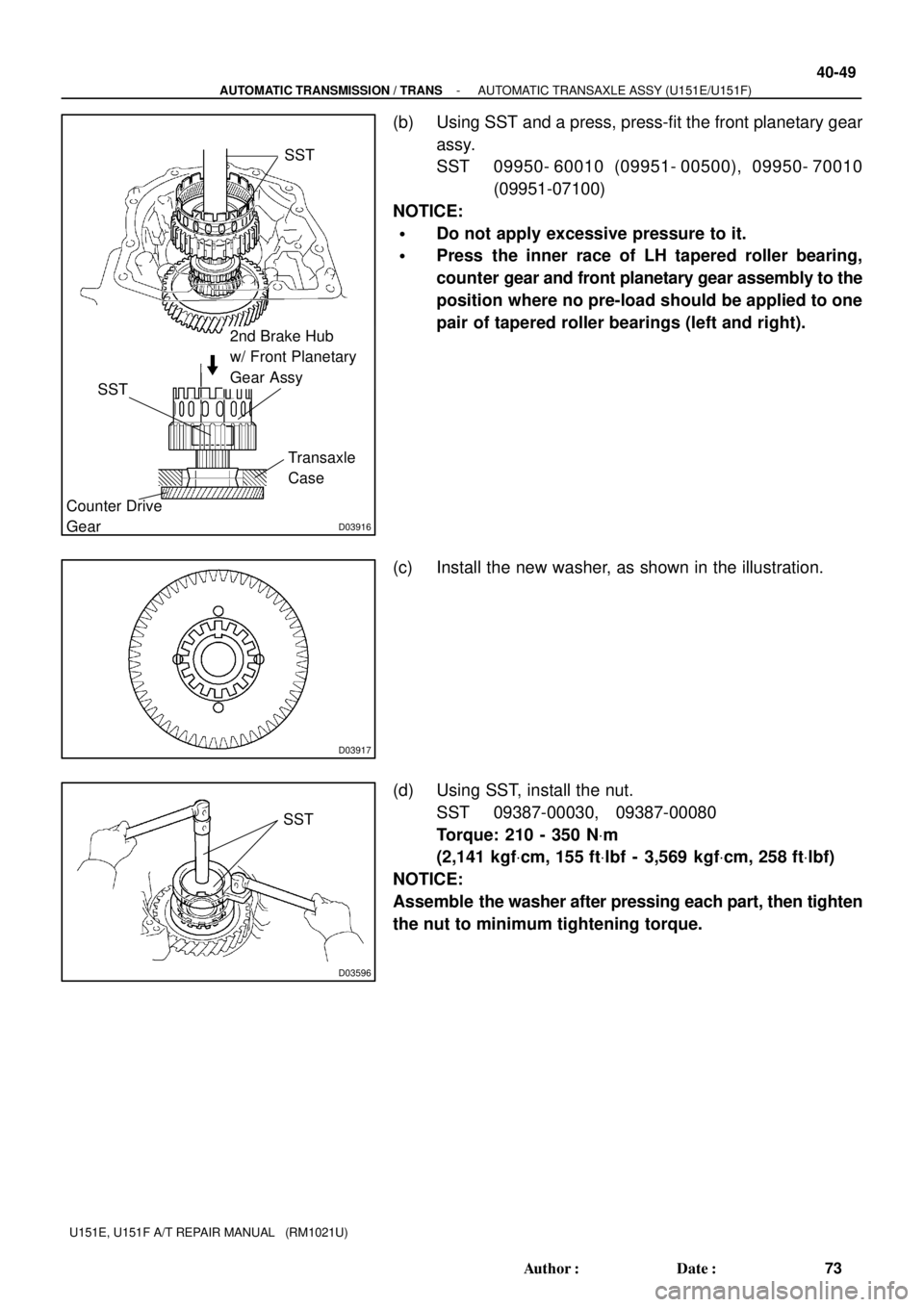
D03916
SST
Counter Drive
GearTransaxle
Case
2nd Brake Hub
w/ Front Planetary
Gear Assy
SST
D03917
D03596
SST
- AUTOMATIC TRANSMISSION / TRANSAUTOMATIC TRANSAXLE ASSY (U151E/U151F)
40-49
73 Author�: Date�:
U151E, U151F A/T REPAIR MANUAL (RM1021U)
(b) Using SST and a press, press-fit the front planetary gear
assy.
SST 09950- 60010 (09951- 00500), 09950- 70010
(09951-07100)
NOTICE:
�Do not apply excessive pressure to it.
�Press the inner race of LH tapered roller bearing,
counter gear and front planetary gear assembly to the
position where no pre-load should be applied to one
pair of tapered roller bearings (left and right).
(c) Install the new washer, as shown in the illustration.
(d) Using SST, install the nut.
SST 09387-00030, 09387-00080
Torque: 210 - 350 NVm
(2,141 kgfVcm, 155 ftVlbf - 3,569 kgfVcm, 258 ftVlbf)
NOTICE:
Assemble the washer after pressing each part, then tighten
the nut to minimum tightening torque.
Page 122 of 969

74 Author�: Date�:
U151E, U151F A/T REPAIR MANUAL (RM1021U)
(e")
D03918
SST
D08074
Lock Washer
C89123
C
BA
Input Sun Gear
D
40-50
- AUTOMATIC TRANSMISSION / TRANSAUTOMATIC TRANSAXLE ASSY (U151E/U151F)
74 Author�: Date�:
U151E, U151F A/T REPAIR MANUAL (RM1021U)
(e) Using SST and a torque wrench, measure the turning
torque of the bearing while rotating SST at 60 rpm. When
the measured value is not within the specified value,
gradually tighten the nut until it reaches the specified val-
ue.
SST 09387-00080
Turning torque at 60 rpm:
New Bearing
0.51 - 1.02 NVm (5.1 - 10.0 kgfVcm, 4.4 - 8.7 in.Vlbf)
Used Bearing
0.26 - 0.51 NVm (2.7 - 5.2 kgfVcm, 2.3 - 4.5 in.Vlbf)
HINT:
Use a torque wrench with a fulcrum length of 160 mm (6.3 in.).
(f) Tighten the nut gradually until the specified rotation
torque of tapered roller bearing is measured.
Torque: 350 NVm (3,569 kgfVcm, 258 ftVlbf) (a limit)
(g) Using a chisel and hammer, stake the front lock washer.
98. INSTALL INPUT SUN GEAR
(a) Coat the 2 thrust bearings with ATF.
(b) Install the 2 thrust bearings, the bearing race and the front
planetary sun gear to the front planetary gear assy.
NOTICE:
�Install the bearing race on the side of the front plane-
tary carrier. Be careful about the orientation of the
race.
�Installing thrust bearing and front sun gears, be care-
ful about the orientation of the parts.
�Install the bearing race on the side of the front sun
gear. Be careful about the orientation of the race.
�Install the thrust bearing and the race after holding
the parts on the rear planetary carrier by applying
grease. Be sure the assembling order.
Page 128 of 969

80 Author�: Date�:
U151E, U151F A/T REPAIR MANUAL (RM10")
D26470
D
D26390
D03923
D26391
Brake Apply
Tube
Clutch Apply Tube
40-56
- AUTOMATIC TRANSMISSION / TRANSAUTOMATIC TRANSAXLE ASSY (U151E/U151F)
80 Author�: Date�:
U151E, U151F A/T REPAIR MANUAL (RM1021U)
(e) Using vernier calipers and a simple straightedge, mea-
sure the position shown in the illustration.
(f) Calculate the end play value using the following formula.
Select a thrust bearing which satisfies the end play value
and install it.
End play: 0.244 - 0.901 mm (0.0096 - 0.0355 in.)
NOTICE:
Make sure that the no colored race side is facing the direct
clutch assy.
HINT:
End play = Dimension D - Dimension C
Bearing thickness and diameter : mm (in.)
ThicknessInsideOutside
3.6 (0.1417)56.3 (2.217)75.7 (2.980)
3.8 (0.1496)56.3 (2.217)75.7 (2.980)
111. INSTALL GOVERNOR APPLY GASKET NO.1
(a) Install the 3 new governor apply gaskets No. 1 to the
transaxle case.
112. INSTALL BRAKE APPLY TUBE
(a) Install the clamp to the brake apply tube.
NOTICE:
Make sure to install the clamp to the apply tube before
installing the apply tube to the transaxle case. This pre-
vents the apply tube from being deformed or damaged.
(b) Install the clutch apply tube.
(c) Install the brake apply tube and a bolt to the transaxle
case.
Torque: 5.4 NVm (55 kgfVcm, 48 in.Vlbf)
NOTICE:
Each pipe should be securely inserted until it reaches the
stopper.
Page 129 of 969

40-57
81 Author�: Date�:
U151E, U151F A/T REPAIR MANUAL")
D26766
SST
D26389
Rear Clutch
Oil Seal
Ring Outer
D26388
D26454
FIPG
- AUTOMATIC TRANSMISSION / TRANSAUTOMATIC TRANSAXLE ASSY (U151E/U151F)
40-57
81 Author�: Date�:
U151E, U151F A/T REPAIR MANUAL (RM1021U)
113. INSTALL NEEDLE ROLLER BEARING
(a) Using SST and a press, install the needle roller bearing
to the transaxle rear cover.
SST 09950-60010 (09951-00230, 09952-06010)
Press fit depth: 20.55 - 21.25 mm (0.8091 - 0.8366 in.)
NOTICE:
�Face the inscribed mark side of the bearing race up.
�Repeat the press fit until the specified value is ob-
tained.
(b) Coat a needle roller bearing with ATF.
114. INSTALL REAR CLUTCH OIL SEAL RING OUTER
(a) Coat the 3 new rear clutch oil seal rings with ATF, install
them to the transaxle rear cover.
NOTICE:
The snap ring should be fixed certainly in the groove of the
drum.
115. INSTALL TRANSAXLE CASE NO.1 PLUG
(a) Install the 4 new O-ring to the 4 transaxle case No. 1
plugs.
(b) Install the 4 transaxle case No. 1 plugs to the transaxle
rear cover.
Torque: 7.4 NVm (75 kgfVcm, 65 in.Vlbf)
116. INSTALL TRANSAXLE REAR COVER SUB-ASSY
(a) Remove any packing material and be careful not to get oil
on the contacting surfaces of the transaxle rear cover or
the transaxle case.
(b) Apply FIPG to the cover.
FIPG:
Part No. 08826-00090, THREE BOND 1281 or equiva-
lent.
NOTICE:
Concerning about the amount of the FIPG application, the
amount should be controlled to from even sealing film on
entire flange surface and have slight protrusion of the FIPG
all around of the connecting area. The FIPG shall be ap-
plied continuously on the flange. (Reference value of the
section diameter: f1.2)
Page 130 of 969

82 Author�: Date�:
U151E, U151F A/T REPAIR MANUAL (RM1021U)
(c)")
D26387AA
D26414
Flange
Plate Disc
D26466
Snap Ring
D08082
40-58
- AUTOMATIC TRANSMISSION / TRANSAUTOMATIC TRANSAXLE ASSY (U151E/U151F)
82 Author�: Date�:
U151E, U151F A/T REPAIR MANUAL (RM1021U)
(c) Apply liquid sealer to the ºAº bolt threads.
Sealant:
Part No. 08833-00080, THREE BOND 1344, LOCTITE
242 or equivalent.
(d) Install the 11 bolts.
Torque:
Bolt A: 19.0 NVm (190 kgfVcm, 14 ftVlbf)
Other bolt: 25.0 NVm (250 kgfVcm, 18 ftVlbf)
117. INSTALL UNDERDRIVE CLUTCH DISC NO.2
(a) Coat the 4 discs with ATF.
(b) Install the 4 discs, 4 plates and flange to the transaxle
case.
NOTICE:
Be careful about the order of discs, plate and flange assem-
bly.
(c) Using a screwdriver, install the snap ring.
NOTICE:
The snap ring should be fixed certainly in the groove of the
drum.
118. INSPECT PACK CLEARANCE OF UNDERDRIVE
BRAKE
(a) Using a dial indicator, measure the underdrive brake pack
clearance while applying and releasing compressed air
(392 kPa, 4.0 kgf/cm
2, 57 psi).
Pack clearance: 1.81 - 2.20 mm (0.0713 - 0.0866 in.)
HINT:
Select an appropriate flange from the table below so that it will
meet the specified value.
Flange thickness: mm (in.)
MarkThicknessMarkThickness
13.0 (0.118)43.1 (0.122)
23.2 (0.126)53.3 (0.130)
33.4 (0.134)--
(b) Temporally remove the snap ring and attach to the flange.
(c) Restore the snap ring.
Page 133 of 969

Dimension (2)
D08087
Thrust Bearing Race No.1
- AUTOMATIC TRANSMISSION / TRANSAUTOMATIC TRANSAXLE ASSY (U151E/U151F)
40-61
85 Author�: Date�")
D09693
D03576Pawl Shaft Clamp
D03875
E
D25511
Dimension (1)
Dimension (2)
D08087
Thrust Bearing Race No.1
- AUTOMATIC TRANSMISSION / TRANSAUTOMATIC TRANSAXLE ASSY (U151E/U151F)
40-61
85 Author�: Date�:
U151E, U151F A/T REPAIR MANUAL (RM1021U)
(b) Install the parking lock pawl shaft.
(c) Install the pawl shaft clamp with the bolt.
Torque: 9.8 NVm (100 kgfVcm, 87 in.Vlbf)
(d) Using a straight edge and vernier calipers as shown in the
illustration, measure the gap between the top of the differ-
ential drive pinion in the underdrive planetary gear and
contact surface of the transaxle case and housing (Di-
mension E).
NOTICE:
Note down the dimension E as it is necessary for the follow-
ing process.
(e) As shown in the illustration, measure the 2 places of the
transaxle housing, calculate the dimension F using the
formula.
NOTICE:
Note down the dimension F as it is necessary for the follow-
ing process.
HINT:
Dimension F = Dimension (1) - Dimension (2)
124. INSTALL MULTIPLE DISC CLUTCH CLUTCH HUB
(a) Install the thrust bearing race No.1 to the transaxle case
while checking its direction.
Bearing race diameter: mm (in.)
InsideOutside
Bearing race39.5 (1.555)45.8 (1.803)