Page 237 of 969
C93021
C93024
C93016
C93149
40-38
- AUTOMATIC TRANSMISSION / TRANSFLOOR SHIFT ASSY
2553 Author�: Date�:
2005 LEXUS ES330 REPAIR MANUAL (RM1124U)
36. INSTALL SHIFT LOCK RELEASE BUTTON COVER
(a) Install the shift lock release button cover to the position in-
dicator housing.
37. INSTALL SHIFT LEVER KNOB SUB-ASSY
(a) Install the floor shift lever knob to the shift lever.
38. INSTALL FLOOR SHIFT ASSY
(a) Install the floor shift assy to the vehicle with the 4 bolts.
Torque: 11.8 NVm (122 kgfVcm, 9 ftVlbf)
(b) Connect the shift lock control computer.
(c) Connect the indicator lamp wire connector.
39. INSTALL TRANSMISSION CONTROL CABLE ASSY
(a) Install the floor shift transmission control cable to the shift
lever.
HINT:
Install it with the uneven surface facing up.
Page 238 of 969
C93323
Lock Key
C92370
C93015
C93325
- AUTOMATIC TRANSMISSION / TRANSFLOOR SHIFT ASSY
40-39
2554 Author�: Date�:
2005 LEXUS ES330 REPAIR MANUAL (RM1124U)
40. INSTALL FLOOR SHIFT PARKING LOCK CABLE
ASSY
(a) Using a screwdriver, unlock the claw of the lock key of au-
tomatic adjustment part.
(b) Insert the slide cap into the through hole and install.
(c) Shift the shift lever to P position and turn the ignition
switch to Lock.
(d) Insert the lever pin into the hole of the parking lock cable.
(e) Lock the lock key.
41. INSTALL BATTERY
42. ADJUST SHIFT LEVER POSITION(SEE PAGE 40-40)
43. INSPECT SHIFT LEVER POSITION(SEE PAGE 40-40)
44. INSPECT CHECK KEY INTERLOCK OPERATION(SEE PAGE 40-31)
45. INSPECT CHECK SHIFT LOCK OPERATION(SEE PAGE 40-31)
46. INSPECT CHECK SHIFT LOCK RELEASE BUTTON OPERATION(SEE PAGE 40-31)
47. INSTALL CONSOLE BOX DUCT NO.1(SEE PAGE 55-17)
48. INSTALL AIR DUCT REAR NO.2(SEE PAGE 55-17)
49. INSTALL AIR DUCT REAR NO.1(SEE PAGE 55-17)
Page 240 of 969

FLOOR SHIFT PARKING LOCK CABLE A")
400FV-02
C93015
C92370
C93152
- AUTOMATIC TRANSMISSION / TRANSFLOOR SHIFT PARKING LOCK CABLE ASSY
40-41
2556 Author�: Date�:
2005 LEXUS ES330 REPAIR MANUAL (RM1124U)
FLOOR SHIFT PARKING LOCK CABLE ASSY
REPLACEMENT
1. REMOVE FRONT DOOR SCUFF PLATE LH (SEE PAGE 71-1 1)
2. REMOVE FRONT DOOR SCUFF PLATE RH (SEE PAGE 71-1 1)
3. REMOVE INSTRUMENT PANEL UNDER COVER SUB-ASSY NO.1 (SEE PAGE 71-1 1)
4. REMOVE INSTRUMENT PANEL SUB-ASSY LOWER (SEE PAGE 71-1 1)
5. REMOVE INSTRUMENT PANEL SUB-ASSY UPPER (SEE PAGE 71-1 1)
6. REMOVE INSTRUMENT PANEL INSERT SUB-ASSY LOWER LH (SEE PAGE 71-1 1)
7. REMOVE CONSOLE PANEL UPPER REAR (SEE PAGE 71-1 1)
8. REMOVE CONSOLE BOX CARPET
9. REMOVE CONSOLE BOX ASSY (SEE PAGE 71-1 1)
10. REMOVE INSTRUMENT PANEL FINISH PANEL END LH (SEE PAGE 71-1 1)
11. REMOVE INSTRUMENT PANEL FINISH PANEL END RH (SEE PAGE 71-1 1)
12. REMOVE AIR DUCT REAR NO.1 (SEE PAGE 55-17)
13. REMOVE AIR DUCT REAR NO.2 (SEE PAGE 55-17)
14. REMOVE CONSOLE BOX DUCT NO.1 (SEE PAGE 55-17)
15. REMOVE FLOOR SHIFT PARKING LOCK CABLE
ASSY
(a) Disconnect the parking lock cable end from the lever pin
of the floor shift assembly.
(b) Using a screwdriver, disconnect the parking lock cable
from the floor shift assembly and clamp.
(c) Disconnect the cable clamp.
(d) Turn the ignition switch to ACC or ON.
(e) Using a screwdriver, remove the cable from the upper
bracket.
Page 241 of 969
C93152
C93323
Lock Key
C92370
C93015
C93325
40-42
- AUTOMATIC TRANSMISSION / TRANSFLOOR SHIFT PARKING LOCK CABLE ASSY
2557 Author�: Date�:
2005 LEXUS ES330 REPAIR MANUAL (RM1124U)
16. INSTALL FLOOR SHIFT PARKING LOCK CABLE
ASSY
(a) Turn the ignition switch to ACC or ON.
(b) Connect the cable to the upper bracket.
(c) Connect the cable clamp.
(d) Shift the shift lever to P range and turn the ignition switch
to LOCK.
(e) Using a screwdriver, unlock the claw of the lock key of au-
tomatic adjustment part.
(f) Insert the slide cap into the through hole and install.
(g) Insert the lever pin into the hole of the parking lock cable.
(h) Lock the lock key.
Page 242 of 969
- AUTOMATIC TRANSMISSION / TRANSFLOOR SHIFT PARKING LOCK CABLE ASSY
40-43
2558 Author�: Date�:
2005 LEXUS ES330 REPAIR MANUAL (RM1124U)
17. INSPECT CHECK KEY INTERLOCK OPERATION(See page 40-31)
18. INSTALL CONSOLE BOX DUCT NO.1
19. INSTALL AIR DUCT REAR NO.2
20. INSTALL AIR DUCT REAR NO.1
21. INSTALL INSTRUMENT PANEL FINISH PANEL END RH
22. INSTALL INSTRUMENT PANEL FINISH PANEL END LH
23. INSTALL CONSOLE BOX ASSY
24. INSTALL CONSOLE BOX CARPET
25. INSTALL CONSOLE PANEL UPPER REAR
26. INSTALL INSTRUMENT PANEL INSERT SUB-ASSY LOWER LH
27. INSTALL INSTRUMENT PANEL SUB-ASSY UPPER
28. INSTALL INSTRUMENT PANEL SUB-ASSY LOWER
29. INSTALL INSTRUMENT PANEL UNDER COVER SUB-ASSY NO.1
30. INSTALL FRONT DOOR SCUFF PLATE RH
31. INSTALL FRONT DOOR SCUFF PLATE LH
Page 249 of 969

BRAKE FLUID (From July, 2003)
BLEEDING
HINT:
If any work is done on the bra")
3211W-03
F41694
F41695
F41696
C80826
32-4
- BRAKEBRAKE FLUID
2438 Author�: Date�:
2005 LEXUS ES330 REPAIR MANUAL (RM1124U)
BRAKE FLUID (From July, 2003)
BLEEDING
HINT:
If any work is done on the brake system or if air in the brake lines is suspected, bleed the air from the system.
NOTICE:
Wash off the brake fluied immediately if it comes into contact with a painted surface.
1. FILL RESERVOIR WITH BRAKE FLUID
Fluid: SAE J1703 or FMVSS No. 116 DOT3
2. BLEED MASTER CYLINDER
HINT:
If the master cylinder has been disassembled or if the reservoir
becomes empty, bleed the air from the master cylinder.
(a) Remove the air cleaner assembly with hose.
(b) Disconnect the brake lines from the master cylinder.
SST 09023-00101
(c) Slowly depress the brake pedal and hold it.
(d) Block off the outer holes with your fingers, and release the
brake pedal.
(e) Repeat (c) and (d) 3 or 4 times.
(f) Install the air cleaner assembly with hose.
3. BLEED BRAKE LINE
(a) Connect the vinyl tube to the brake caliper.
(b) Depress the brake pedal several times, then loosen the
bleeder plug with the pedal held down.
(c) At the point when fluid stops coming out, tighten the
bleeder plug, then release the brake pedal.
(d) Repeat (b) and (c) until all the air in the fluid has been bled
out.
(e) Tighten the bleeder plug certainly.
Torque: 8.3 NVm (85 kgfVcm, 73 in.Vlbf)
Page 253 of 969

BRAKE PEDAL SUPPORT ASSY
ADJUSTMENT
1. CHEC")
320DV-02
F41697
Stop Lamp
Switch
Push Rod
Pedal Height
32-8
- BRAKEBRAKE PEDAL SUPPORT ASSY
2442 Author�: Date�:
2005 LEXUS ES330 REPAIR MANUAL (RM1124U)
BRAKE PEDAL SUPPORT ASSY
ADJUSTMENT
1. CHECK AND ADJUST BRAKE PEDAL HEIGHT
(a) Inspect brake pedal height.
Pedal height from asphalt sheet:
144.1 - 154.1 mm (5.673 - 6.067 in.)
(b) Adjust brake pedal height.
(1) Remove the instrument panel finish panel sub-
assy lower and instrument panel insert sub-assy
lower LH.
(2) Disconnect the connector from the stop lamp
switch.
(3) Loosen the stop lamp switch lock nut and remove
the stop lamp switch.
(4) Loosen the clevis lock nut.
(5) Adjust the pedal height by turning the pedal push
rod.
(6) Tighten the push rod lock nut.
Torque: 26 NVm (265 kgfVcm, 19 ftVlbf)
(7) Install the stop lamp switch.
(8) Connect the connector to the stop lamp switch.
(9) Push the brake pedal in 5 - 10 mm (0.20 - 0.39 in.),
turn the stop lamp switch to lock the nut in the posi-
tion where the stop lamp goes off.
(10) After installation, push the brake pedal in 5 - 10 mm
(0.20 - 0.39 in.), check that stop lamp lights up.
(11) Install the instrument panel insert sub-assy lower
LH and instrument panel finish panel sub-assy low-
er.
Page 255 of 969
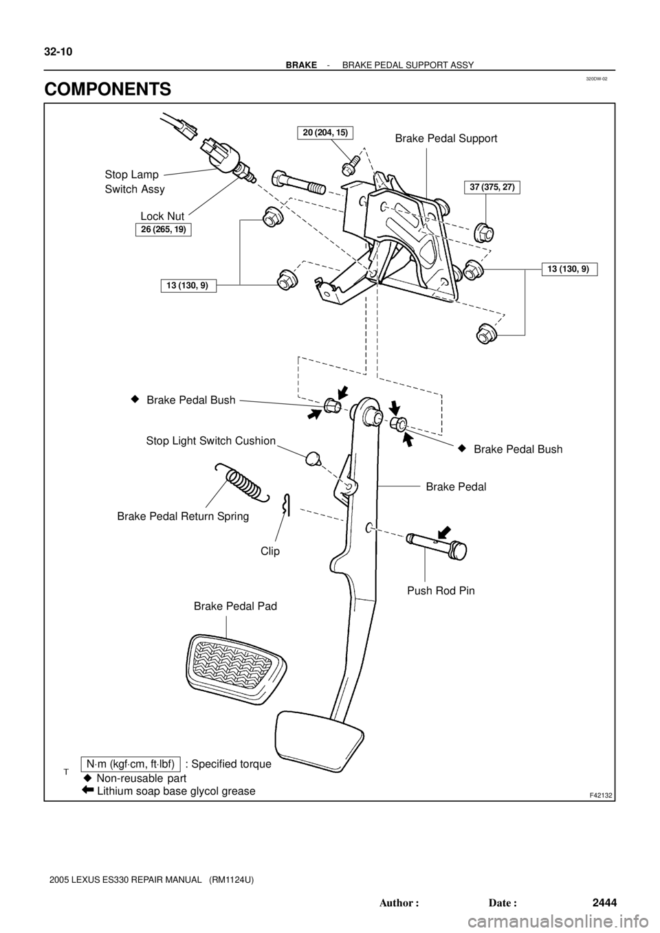
320DW-02
F42132
Brake Pedal Support
Stop Lamp
Switch Assy
Lock Nut
�
Brake Pedal Bush
�
Brake Pedal Bush Stop Light Switch Cushion
Brake Pedal
Push Rod Pin Brake Pedal Return Spring
Clip
Brake Pedal Pad
� Non-reusable part
NVm (kgfVcm, ftVlbf) : Specified torque
Lithium soap base glycol grease
26 (265, 19)
37 (375, 27)
13 (130, 9)
13 (130, 9)
20 (204, 15)
32-10
- BRAKEBRAKE PEDAL SUPPORT ASSY
2444 Author�: Date�:
2005 LEXUS ES330 REPAIR MANUAL (RM1124U)
COMPONENTS