Page 353 of 969

2411 Author�: Date�:
2005 LEXUS ES330 REPAIR MANUAL (RM1124U)
FRONT DRIVE SHAFT (From")
300M5-01
C91611
SST
F40136
C83022
F40147
30-8
- DRIVE SHAFT / PROPELLER SHAFTFRONT DRIVE SHAFT (From July, 2003)
2411 Author�: Date�:
2005 LEXUS ES330 REPAIR MANUAL (RM1124U)
FRONT DRIVE SHAFT (From July, 2003)
OVERHAUL
HINT:
�COMPONENTS: See page 30-4
�Overhaul the RH side following the same procedures as for the LH side.
1. DRAIN AUTOMATIC TRANSAXLE FLUID
2. REMOVE FRONT WHEEL
3. REMOVE FRONT AXLE HUB LH NUT
(a) Using SST and a hammer, unstake the staked part of the
front axle hub LH nut.
SST 09930-00010
NOTICE:
Loosen the staked part of the lock nut completely, other-
wise the screw of the drive shaft may be damaged.
(b) While applying the brake, remove the front axle hub LH
nut.
4. DISCONNECT FRONT STABILIZER LINK ASSY LH
(a) Remove the nut, and separate the stabilizer link assy LH.
HINT:
If the ball joint turns together with the nut, use a hexagon
wrench (6 mm) to hold the stud.
5. DISCONNECT SPEED SENSOR FRONT LH
(a) Remove the bolt and clip, and separate the sensor wire
and hose from the shock absorber.
NOTICE:
Be careful not to damage the speed sensor.
(b) Remove the bolt, and separate the speed sensor front LH
from the steering knuckle.
NOTICE:
Prevent foreign matter from adhering to the speed sensor.
Page 366 of 969

30-21
2424 Author�: Date�:
2005 LEXUS ES330 REPAIR MANUA")
F40230
SST
SST
F11547
SST
Spanner
V Block
F40231
SST
F40157
SST
SST
- DRIVE SHAFT / PROPELLER SHAFTFRONT AXLE HUB SUB-ASSY LH (From July, 2003)
30-21
2424 Author�: Date�:
2005 LEXUS ES330 REPAIR MANUAL (RM1124U)
14. REMOVE FRONT AXLE HUB LH BEARING
(a) Place the bearing inner race (outside) on the front axle
hub LH bearing.
(b) Using SST and a press, press the front axle hub LH bear-
ing until it contacts the SST.
SST 09527- 17011, 09950- 60010 (09951- 00600),
09950-70010 (09951-07100)
(c) Using a spanner to make the steering knuckle LH horizon-
tal, fix it to the V block as shown in the illustration.
NOTICE:
Be sure that the steering knuckle is horizontally posi-
tioned.
(d) Using SST and a press, remove the front axle hub LH
bearing.
SST 09950- 60010 (09951- 00600), 09950- 70010
(09951-07100)
15. INSTALL FRONT AXLE HUB LH BEARING
(a) Using SST and a press, install a new front axle hub LH
bearing to the steering knuckle LH.
SST 09950- 60020 (09951- 00790), 09950- 70010
(09951-07100)
16. INSTALL DISC BRAKE DUST COVER FRONT LH
(a) Place the disc brake dust cover front LH and using a torx wrench (T30), torque the 4 bolts.
Torque: 8.3 NVm (85 kgfVcm, 73 in.Vlbf)
17. INSTALL FRONT AXLE HUB SUB-ASSY LH
(a) Using SST and a press, install the front axle hub sub-
assy LH.
SST 09608- 32010, 09950- 60020 (09951- 00790),
09950-70010 (09951-07100)
Page 404 of 969
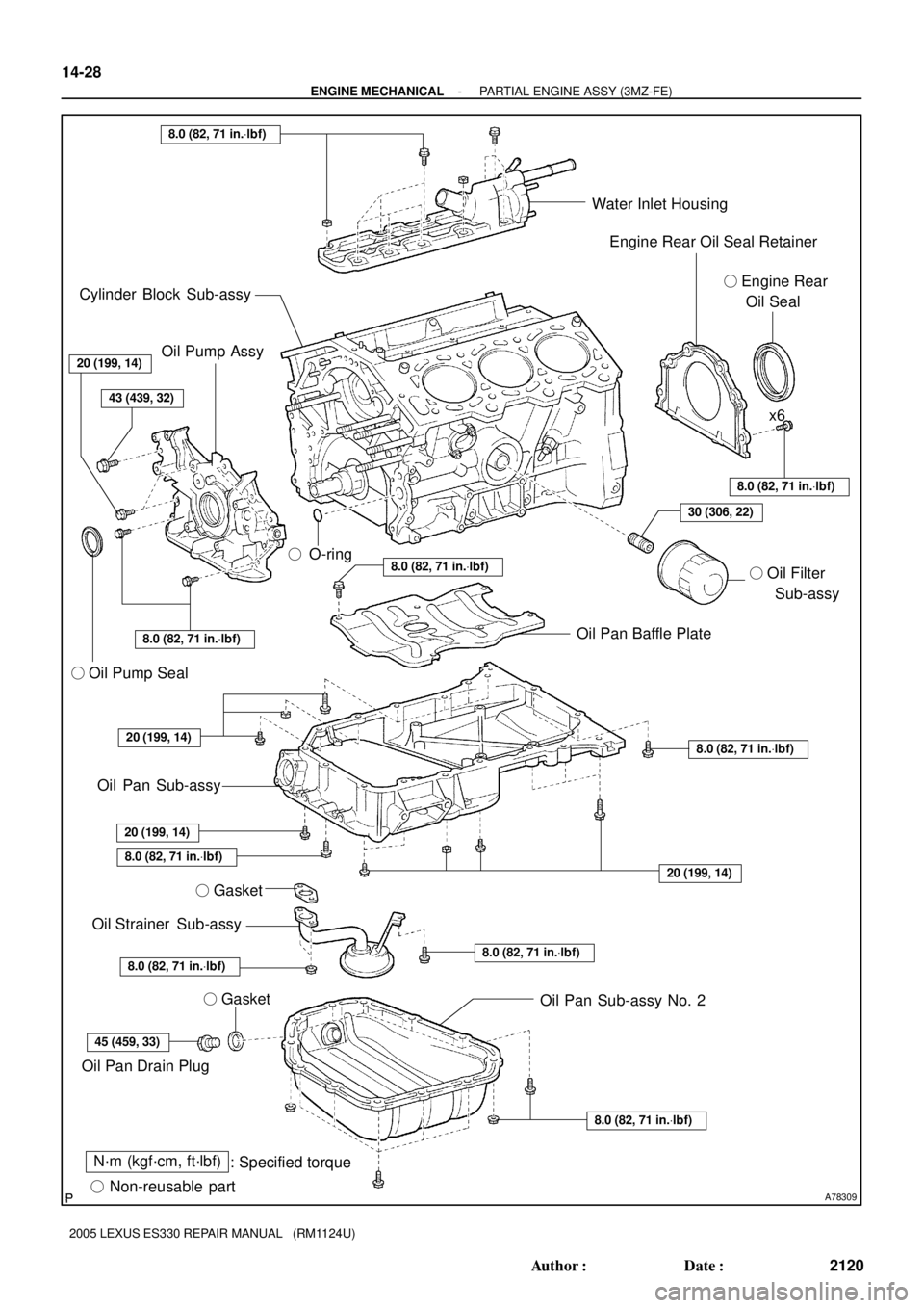
A78309
N´m (kgf´cm, ft´lbf)
: Specified torque
� Non-reusable part� O-ring
� Gasket
8.0 (82, 71 in.Vlbf)
8.0 (82, 71 in.Vlbf)
45 (459, 33)
8.0 (82, 71 in.Vlbf)
8.0 (82, 71 in.Vlbf)
8.0 (82, 71 in.Vlbf)
8.0 (82, 71 in.Vlbf)
30 (306, 22)
43 (439, 32)
20 (199, 14)
8.0 (82, 71 in.Vlbf)
20 (199, 14)
8.0 (82, 71 in.Vlbf)
8.0 (82, 71 in.Vlbf)
20 (199, 14)
Oil Pan Sub-assy No. 2 � Gasket Oil Strainer Sub-assy
Oil Pan Drain PlugOil Pan Sub-assy � Oil Pump SealOil Pan Baffle Plate� Oil Filter
Sub-assyx6 Water Inlet Housing
Engine Rear Oil Seal Retainer
� Engine Rear
Oil Seal Cylinder Block Sub-assy
20 (199, 14)
Oil Pump Assy
14-28
- ENGINE MECHANICALPARTIAL ENGINE ASSY (3MZ-FE)
2120 Author�: Date�:
2005 LEXUS ES330 REPAIR MANUAL (RM1124U)
Page 406 of 969

2122 Author�: Date�:
2005 LEXUS ES330 REPAIR MANUAL (RM1124U)
37. DISCONNECT STEERING GEAR OUTLET RETURN
TUBE
38. REMOVE GLOVE COM")
A60073
A59893
14-30
- ENGINE MECHANICALPARTIAL ENGINE ASSY (3MZ-FE)
2122 Author�: Date�:
2005 LEXUS ES330 REPAIR MANUAL (RM1124U)
37. DISCONNECT STEERING GEAR OUTLET RETURN
TUBE
38. REMOVE GLOVE COMPARTMENT DOOR ASSY (See page 10-22)
39. SEPARATE ENGINE WIRE
(a) Disconnect the engine wire harness from the ECM and
junction block.
(b) Disconnect the engine wire harness from the engine room
junction block.
(1) Remove the nut, then separate the engine wire har-
ness.
(2) Using a screwdriver, release the engine room junc-
tion block. Separate the engine wire harness by
pulling it upward.
(c) Remove the 2 nuts, then pull out the engine wire harness.
(d) Remove the body ground.
40. REMOVE EXHAUST PIPE NO.1 SUPPORT BRACKET FRONT (See page 15-2)
41. REMOVE EXHAUST PIPE NO.1 SUPPORT BRACKET REAR (See page 15-2)
42. REMOVE EXHAUST PIPE ASSY FRONT (See page 15-2)
43. DISCONNECT FRONT STABILIZER LINK ASSY LH (See page 30-8)
44. DISCONNECT FRONT STABILIZER LINK ASSY RH
HINT:
Perform the same procedure as above on the opposite side.
45. REMOVE FRONT AXLE HUB LH NUT (See page 30-8)
SST 09930-00010
46. REMOVE FRONT AXLE HUB RH NUT
SST 09930-00010
HINT:
Perform the same procedure as above on the opposite side.
47. SEPARATE SPEED SENSOR FRONT LH (See page 30-8)
48. SEPARATE SPEED SENSOR FRONT RH
HINT:
Perform the same procedure as above on the opposite side.
49. SEPARATE TIE ROD ASSY LH (See page 30-8)
SST 09628-6201 1
50. SEPARATE TIE ROD ASSY RH
SST 09628-6201 1
HINT:
Perform the same procedure as above on the opposite side.
Page 407 of 969

14-31
2123 Author�: Date�:
2005 LEXUS ES330 REPAIR MANUAL (RM1124U)
51. SEPARATE FRONT SUSPENSION ARM SUB-ASSY LOWER NO.1 LH (See")
A59877
A59878
A36439
- ENGINE MECHANICALPARTIAL ENGINE ASSY (3MZ-FE)
14-31
2123 Author�: Date�:
2005 LEXUS ES330 REPAIR MANUAL (RM1124U)
51. SEPARATE FRONT SUSPENSION ARM SUB-ASSY LOWER NO.1 LH (See page 30-8)
52. SEPARATE FRONT SUSPENSION ARM SUB-ASSY LOWER NO.1 RH
HINT:
Perform the same procedure as above on the opposite side.
53. SEPARATE FRONT AXLE ASSY LH (See page 30-8)
54. SEPARATE FRONT AXLE ASSY RH
HINT:
Perform the same procedure as above on the opposite side.
55. SEPARATE STEERING INTERMEDIATE SHAFT ASSY (See page 51-21)
56. REMOVE ENGINE ASSEMBLY WITH TRANSAXLE
(a) Set the engine lifter.
(b) Remove the 4 bolts and 2 nuts, then remove the frame
side rail plate RH and LH.
(c) Remove the 4 bolts and 2 nuts, then remove the front sus-
pension member brace rear RH and LH.
(d) Carefully remove the engine assembly from the vehicle.
(e) Install the engine hanger No. 2 in the correct direction as
shown in the illustration.
Torque: 20 NVm (199 kgfVcm, 14 ftVlbf)
HINT:
Engine hanger No. 212282-20020
Bolt91621-60822
(f) Attach the engine sling and hang the engine assembly
with the chain block.
57. REMOVE VANE PUMP V BELT (See page 14-5)
Page 417 of 969

14-41
2133 Author�: Date�:
2005 LEXUS ES330 REPAIR MANUAL (RM1124U)
18. REMOVE TIMING BELT
(a)")
A78326
Turn
A05052
A52840
A78327
Approximately 60�
Turn
- ENGINE MECHANICALPARTIAL ENGINE ASSY (3MZ-FE)
14-41
2133 Author�: Date�:
2005 LEXUS ES330 REPAIR MANUAL (RM1124U)
18. REMOVE TIMING BELT
(a) Set the No. 1 cylinder to the TDC/compression.
(1) Temporarily install the crankshaft pulley bolt and
washer to the crankshaft.
(2) Turn the crankshaft clockwise, then align the timing
mark of the crankshaft timing pulley with the oil
pump body.
(3) Check that the timing marks of the camshaft timing
pulleys and the timing belt No. 3 cover are aligned.
If not, turn the crankshaft by 1 revolution (360�).
(4) Remove the crankshaft pulley bolt.
(b) If reusing the timing belt, check that there are 3 installa-
tion marks on the timing belt as shown in the illustration.
(1) If the installation marks have disappeared, put new
installation marks on the timing belt before remov-
ing.
(c) Set the No. 1 cylinder to approximately 60� BTDC/com-
pression.
(1) Turn the crankshaft counterclockwise by approxi-
mately 60�.
NOTICE:
If the timing belt is disengaged, having the crankshaft
pulley set at the wrong angle can cause contact of the pis-
ton head with the valve head when removing the camshaft
timing pulley and camshaft, which causes damage. So al-
ways set the crankshaft pulley at the correct angle.
(d) Remove the timing belt tensioner.
NOTICE:
Do not reinstall the tensioner with its plunger extended.
Page 421 of 969

14-45
2137 Author�: Date�:
2005 LEXUS ES330 REPAIR MANUAL (RM1124U)
(c")
A78712
10
12
3
4
5
67
89
A78713
10
1
2
3
4
5
6
7
89
A05739
A78714Convex Portion
- ENGINE MECHANICALPARTIAL ENGINE ASSY (3MZ-FE)
14-45
2137 Author�: Date�:
2005 LEXUS ES330 REPAIR MANUAL (RM1124U)
(c) Using several steps, loosen and remove the 10 bearing
cap bolts uniformly in the sequence shown in the illustra-
tion. Remove the 5 bearing caps and No. 3 camshaft.
NOTICE:
�Do not pry out the camshaft.
�Be careful not to damage the contact surface of the
cylinder head that receives the shaft thrust.
30. REMOVE NO.4 CAMSHAFT SUB-ASSY
(a) Using several steps, loosen and remove the 10 bearing
cap bolts uniformly in the sequence shown in the illustra-
tion. Remove the 5 bearing caps and No. 4 camshaft.
NOTICE:
�Do not pry out the camshaft.
�Be careful not to damage the contact surface of the
cylinder head that receives the shaft thrust.
(b) Remove the oil seal from the No. 4 camshaft.
31. INSPECT CAMSHAFT TIMING GEAR ASSY
(a) Clamp the camshaft in a vise on the hexagonal lobe.
(b) Check that the VVT-i will not turn.
(c) Cover all the oil ports with vinyl tape except the port on the
advance angle side (nearest to the convex portion)
shown in the illustration.
(d) Using the air gun, apply about 100 kPa (1 kgf/cm
2, 14 psi)
of air pressure to the port on the advance angle side.
NOTICE:
Some oil spraying will occur. Be prepared to catch the
spray with a shop rag.
HINT:
This operation releases the lock pin for the most retard angle
lock.
(e) Under the condition above, turn the VVT-i to the advance
angle side (the direction of the white arrow in the illustra-
tion) by hand.
Standard: Must turn
HINT:
Depending on the air pressure, the VVT-i will turn to the ad-
vance angle side without applying force by hand. Also, if the
pressure can be hardly applied because of the air leakage from
the port, the lock pin might not be released easily.
Page 422 of 969

2138 Author�: Date�:
2005 LEXUS ES330 REPAIR MANUAL (RM1124U)
(f) Check that the VVT-i moves freely within about 30�
range.")
A05739
A05740
P12596
14-46
- ENGINE MECHANICALPARTIAL ENGINE ASSY (3MZ-FE)
2138 Author�: Date�:
2005 LEXUS ES330 REPAIR MANUAL (RM1124U)
(f) Check that the VVT-i moves freely within about 30�
range. Avoid moving the VVT-i unit to the most retard
angle position as the lock pin will engage again.
Standard: Smooth movable range is about 30�
(g) Turn the VVT-i by hand, then lock it at the most retard
angle position.
32. REMOVE CAMSHAFT TIMING GEAR ASSY
NOTICE:
Do not remove or install the camshaft timing gear (VVT-i)
unless you are replacing the VVT-i or camshaft.
(a) Clamp the camshaft in a vise on the hexagonal lobe.
NOTICE:
Be careful not to damage the camshaft.
(b) Using a 46 mm socket wrench, remove the lock nut by
turning it clockwise.
NOTICE:
�Remove it with the lock pin engaged and locked at the
most retard angle position.
�The lock nut has LH threads.
�Never use any tools other than the socket wrench.
Other tools will deform the cam angle rotor.
(c) Remove the camshaft VVT-i.
NOTICE:
Never remove the 3 bolts on the gear.
If it is difficult to remove VVT-i, tap it lightly using a plastic-faced
hammer, then remove it.
33. REMOVE CAMSHAFT SUB GEAR
(a) Clamp the camshaft in a vise on the hexagonal lobe.
NOTICE:
Be careful not to damage the camshaft.