Page 131 of 969
D03925
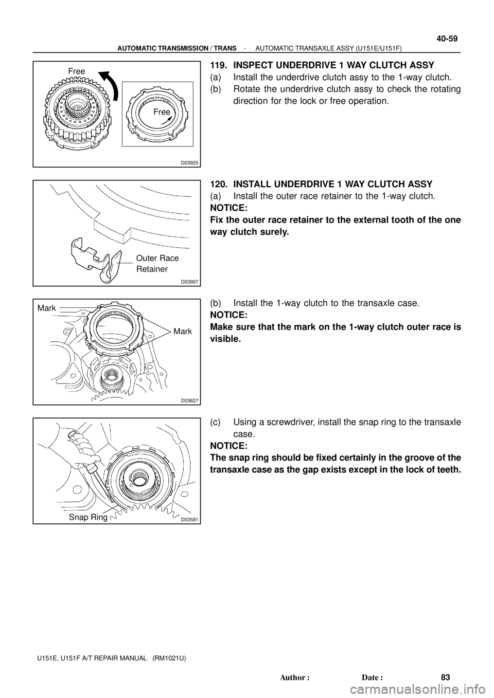
Free
Free
D03907
Outer Race
Retainer
D03627
Mark
Mark
D03581Snap Ring
- AUTOMATIC TRANSMISSION / TRANSAUTOMATIC TRANSAXLE ASSY (U151E/U151F)
40-59
83 Author�: Date�:
U151E, U151F A/T REPAIR MANUAL (RM1021U)
119. INSPECT UNDERDRIVE 1 WAY CLUTCH ASSY
(a) Install the underdrive clutch assy to the 1-way clutch.
(b) Rotate the underdrive clutch assy to check the rotating
direction for the lock or free operation.
120. INSTALL UNDERDRIVE 1 WAY CLUTCH ASSY
(a) Install the outer race retainer to the 1-way clutch.
NOTICE:
Fix the outer race retainer to the external tooth of the one
way clutch surely.
(b) Install the 1-way clutch to the transaxle case.
NOTICE:
Make sure that the mark on the 1-way clutch outer race is
visible.
(c) Using a screwdriver, install the snap ring to the transaxle
case.
NOTICE:
The snap ring should be fixed certainly in the groove of the
transaxle case as the gap exists except in the lock of teeth.
Page 132 of 969

84 Author�: Date�:
U151E, U1")
D03580
D09691
Parking Lock Pawl
Spring
Pawl Pin
D26386
D03579
Underdrive
Planetary
Gear Assy
40-60
- AUTOMATIC TRANSMISSION / TRANSAUTOMATIC TRANSAXLE ASSY (U151E/U151F)
84 Author�: Date�:
U151E, U151F A/T REPAIR MANUAL (RM1021U)
121. INSTALL UNDERDRIVE CLUTCH ASSY
(a) Coat the bearing and bearing race with petroleum jelly,
install them onto the underdrive clutch.
Bearing and bearing race diameter: mm (in.)
InsideOutside
Bearing37.73 (1.4854)58.0 (2.2835)
Race29.9 (1.1772)55.5 (2.185)
(b) Install the underdrive clutch assy to the transaxle case.
NOTICE:
Installing the underdrive clutch drum sub-assy, be sure
not to damage the oil seal ring.
122. INSTALL PARKING LOCK PAWL
(a) Install the pawl pin and spring to the parking lock pawl.
(b) Temporarily install the parking lock pawl, shaft and spring
to the transaxle case, as shown in the illustration.
123. INSTALL UNDERDRIVE PLANETARY GEAR ASSY
(a) Install the underdrive planetary gear assy to the transaxle
case.
NOTICE:
Engage all the discs of underdrive clutch and hub splines
of the underdrive planetary gear assy firmly and assemble
them securely.
Page 133 of 969

Dimension (2)
D08087
Thrust Bearing Race No.1
- AUTOMATIC TRANSMISSION / TRANSAUTOMATIC TRANSAXLE ASSY (U151E/U151F)
40-61
85 Author�: Date�")
D09693
D03576Pawl Shaft Clamp
D03875
E
D25511
Dimension (1)
Dimension (2)
D08087
Thrust Bearing Race No.1
- AUTOMATIC TRANSMISSION / TRANSAUTOMATIC TRANSAXLE ASSY (U151E/U151F)
40-61
85 Author�: Date�:
U151E, U151F A/T REPAIR MANUAL (RM1021U)
(b) Install the parking lock pawl shaft.
(c) Install the pawl shaft clamp with the bolt.
Torque: 9.8 NVm (100 kgfVcm, 87 in.Vlbf)
(d) Using a straight edge and vernier calipers as shown in the
illustration, measure the gap between the top of the differ-
ential drive pinion in the underdrive planetary gear and
contact surface of the transaxle case and housing (Di-
mension E).
NOTICE:
Note down the dimension E as it is necessary for the follow-
ing process.
(e) As shown in the illustration, measure the 2 places of the
transaxle housing, calculate the dimension F using the
formula.
NOTICE:
Note down the dimension F as it is necessary for the follow-
ing process.
HINT:
Dimension F = Dimension (1) - Dimension (2)
124. INSTALL MULTIPLE DISC CLUTCH CLUTCH HUB
(a) Install the thrust bearing race No.1 to the transaxle case
while checking its direction.
Bearing race diameter: mm (in.)
InsideOutside
Bearing race39.5 (1.555)45.8 (1.803)
Page 138 of 969

90 Author�: Date�:
U151E, U151F A/T REPAIR MANUAL (RM")
D26382
Parking Lock Rod Sub-assy
D03565
Spacer
D03564
D26765
D03559
40-66
- AUTOMATIC TRANSMISSION / TRANSAUTOMATIC TRANSAXLE ASSY (U151E/U151F)
90 Author�: Date�:
U151E, U151F A/T REPAIR MANUAL (RM1021U)
135. INSTALL PARKING LOCK ROD SUB-ASSY
(a) Install the parking lock rod to the manual valve lever.
136. INSTALL MANUAL VALVE LEVER SUB-ASSY
(a) Install a new spacer and manual valve lever shaft to the
transaxle case.
NOTICE:
Do not damage on the oil seal during assembling the shaft
to the transaxle case.
(b) Using a pin punch and hammer, drive in a new pin.
(c) Turn the spacer and the lever shaft to align the small hole
for locating the staking position in the spacer with the
staking position mark on the lever shaft.
(d) Using a pin punch, stake the spacer through the small
hole.
(e) Check that the spacer does not turn.
137. INSTALL MANUAL VALVE LEVER SHAFT RETAINER
SPRING
(a) Using needle-nose pliers, install the retainer spring.
NOTICE:
Hang the spring on the shaft certainly.
Page 139 of 969

40-67
91 Author�: Date�:
U151E, U151F A/T REPAIR MANUAL (RM")
D03561
D03560
B
A
D03904
O-ring
B-3 Accumulator Piston
D25512
AT F
- AUTOMATIC TRANSMISSION / TRANSAUTOMATIC TRANSAXLE ASSY (U151E/U151F)
40-67
91 Author�: Date�:
U151E, U151F A/T REPAIR MANUAL (RM1021U)
138. INSTALL PARKING LOCK PAWL BRACKET
(a) Install the parking lock pawl bracket with the 2 bolts.
Torque: 20 NVm (205 kgfVcm, 15 ftVlbf)
Bolt length: 25 mm (0.984 in.)
NOTICE:
Be sure the parking rod is placed between the parking pawl
and the guide of the parking bracket when the parking
bracket is assembled.
139. INSTALL MANUAL DETENT SPRING SUB-ASSY
(a) Install the manual detent spring with the 2 bolts.
NOTICE:
Make sure to install the manual detent spring and cover in
this order.
HINT:
Tighten them in the order, A and B.
Torque:
Bolt A: 20 NVm (205 kgfVcm, 15 ftVlbf)
Bolt B: 12 NVm (120 kgfVcm, 9 ftVlbf)
Bolt length:
Bolt A: 27 mm (1.063 in.)
Bolt B: 16 mm (0.630 in.)
140. INSTALL B-3 ACCUMULATOR PISTON
(a) Coat a new O-ring with ATF, install it to the B-3 accumula-
tor piston.
NOTICE:
Install the O-ring to the accumulator piston and the accu-
mulator sleeve not to have a twist and a protrusion. More-
over, apply enough ATF prior to assembling. Be sure to the
installed position.
(b) Coat the piston with ATF, install it to the transaxle case.
NOTICE:
Install the springs to each accumulator piston with check-
ing of the identification color or each spring.
Accumulator spring:
Free length
Outer diameter mm (in.)Color
Inner 62.00 (2.4409) /
15.50 (0.610)Purple
Outer 74.23 (2.9224) /
21.70 (0.854)Purple
Page 142 of 969

94 Author�: Date�:
U151E, U151F A/T REPAIR")
D03547
Transmission Wire
C91927
GFE
A
B
C
D
C91933
A
CB
B
A
C
�
�
C91932
O-ring
40-70
- AUTOMATIC TRANSMISSION / TRANSAUTOMATIC TRANSAXLE ASSY (U151E/U151F)
94 Author�: Date�:
U151E, U151F A/T REPAIR MANUAL (RM1021U)
(b) Install the transmission wire retaining bolt.
Torque: 5.4 NVm (55 kgfVcm, 48 in.Vlbf)
148. CONNECT TRANSMISSION WIRE
(a) Coat a O-ring of the ATF temperature sensor with ATF.
(b) Install the ATF temperature sensor, with the lock plate and
bolt.
Torque: 6.6 NVm (67 kgfVcm, 58 in.Vlbf)
(c) Connect the 7 solenoid connectors.
NOTICE:
�Connect the connector to A, B, C, D, E, F, G, from
shorter one.
�Apply ATF to the bolt.
149. INSTALL TRANSMISSION VALVE BODY ASSY
(a) Make sure that the manual valve lever position, install the
valve body with 17 bolts to the transaxle case.
Torque: 11 NVm (110 kgfVcm, 8 ftVlbf)
Bolt length:
Bolt A: 41 mm (1.614 in.)
Bolt B: 57 mm (2.244 in.)
Bolt C: 25 mm (0.984 in.)
NOTICE:
�Push the valve body against the accumulator piston
spring and the check ball body to install it.
�When installing the valve body to the transaxle case,
do not hold the solenoids.
�Tighten temporarily those bolts marked by � in the il-
lustration first because they are positioning bolts.
150. INSTALL VALVE BODY OIL STRAINER ASSY
(a) Coat a new O-ring with ATF, install it to the oil strainer.
NOTICE:
Assemble the O-ring carefully not to have a twist and a
pinching. Moreover, apply enough ATF to the O-ring prior
to assembling.
Page 145 of 969
D09641
D09642
D09643
D09644
- AUTOMATIC TRANSMISSION / TRANSAUTOMATIC TRANSAXLE ASSY (U151E/U151F)
40-73
97 Author�: Date�:
U151E, U151F A/T REPAIR MANUAL (RM1021U)
(d) Turn the lever counterclockwise until it stops, and then
turn it clockwise 2 notches.
(e) Remove the control shaft lever.
(f) Align the groove with neutral basic line.
(g) Tighten the 2 bolts.
Torque: 5.4 NVm (55 kgfVcm, 48 in.Vlbf)
(h) Using a screwdriver, stake the nut with the nut stopper.
(i) Install the control shaft lever, washer and nut.
Torque: 13 NVm (130 kgfVcm, 9 ftVlbf)
158. INSTALL SPEEDOMETER DRIVEN HOLE (ATM) COVER SUB-ASSY
(a) Coat a new O-ring with ATF and install it to the speedometer driven hole cover.
(b) Install the bolt and speedometer driven hole cover sub-assy to the transaxle assy.
Torque: 6.9 NVm (70 kgfVcm, 61 ftVlbf)
Page 171 of 969
40-99
123 Author�: Da")
4006K-03
D25593
SST Underdrive
Planetary Gear
D25594
SST
D03686
SST
D03687
Underdrive
Planetary Gear
- AUTOMATIC TRANSMISSION / TRANSUNDERDRIVE PLANETARY GEAR
ASSY (U151E/U151F)40-99
123 Author�: Date�:
U151E, U151F A/T REPAIR MANUAL (RM1021U)
UNDERDRIVE PLANETARY GEAR ASSY (U151E/U151F)
OVERHAUL
1. INSPECT UNDERDRIVE PLANETARY GEAR
PRELOAD
(a) Using SST, fix the underdrive planetary gear assy.
SST 09387-00050
(b) Using SST and a torque wrench, measure the turning
torque of underdrive planetary gear assy while rotating
the torque wrench at 60 rpm.
SST 09387-00050
Turning torque at 60 rpm.:
0.50 - 1.42 NVm (5.1 - 14.5 kgfVcm, 0.06 - 0.17 in.Vlbf)
HINT:
Use a torque wrench with a fulcrum length of 160 mm (6.3 in.).
2. REMOVE FRONT PLANETARY GEAR NUT
(a) Using SST, loosen the staked part of the lock nut.
SST 09930- 00010 (09931- 00010, 09931- 00020),
09387-00050
(b) Clamp the underdrive planetary gear in soft jaw vise.
NOTICE:
Be careful not to damage the differential drive pinion.