Page 665 of 969
160QI-01
A80823
A80824
A80298
Jiggle Valve15�
15� 16-16
- COOLINGTHERMOSTAT (3MZ-FE)
2294 Author�: Date�:
2005 LEXUS ES330 REPAIR MANUAL (RM1124U)
THERMOSTAT (3MZ-FE)
REPLACEMENT
1. DISCONNECT BATTERY NEGATIVE TERMINAL
2. DRAIN ENGINE COOLANT (See page 16-9)
3. REMOVE RADIATOR LOWER AIR DEFLECTOR (See page 19-5)
4. REMOVE AIR CLEANER INLET ASSY (See page 19-5)
5. REMOVE AIR CLEANER ASSY (See page 19-5)
6. REMOVE WATER INLET PIPE
(a) Remove the bolt and water inlet pipe.
(b) Remove the O-ring from the water inlet pipe.
7. REMOVE WATER INLET
(a) Disconnect the wire harness clamp.
(b) Remove the 3 nuts and water inlet.
8. REMOVE THERMOSTAT
9. INSTALL THERMOSTAT
(a) Install a new gasket to the thermostat.
(b) Align the thermostat jiggle valve with the upper stud bolt,
then insert the thermostat in the water inlet housing.
HINT:
The jiggle valve may be set within 15 � of either side of the pre-
scribed position.
10. INSTALL WATER INLET
Torque: 8.0 NVm (82 kgfVcm, 71 in.Vlbf)
Page 666 of 969
- COOLINGTHERMOSTAT (3MZ-FE)
16-17
2295 Author�: Date�:
2005 LEXUS ES330 REPAIR MANUAL (RM1124U)
11. INSTALL WATER INLET PIPE
(a) Install a new O-ring to the water inlet pipe.
(b) Apply soapy water to the O-ring.
(c) Connect the water inlet pipe to the water inlet.
(d) Install the bolt which is used to fixes the water inlet pipe to the cylinder head.
Torque: 20 NVm (199 kgfVcm,
14 ftVlbf)
12. INSTALL AIR CLEANER ASSY (See page 19-5)
13. INSTALL AIR CLEANER INLET ASSY (See page 19-5)
14. CHECK CONNECTION OF VACUUM HOSE (See page 14-29)
15. ADD ENGINE COOLANT (See page 16-9)
16. CHECK FOR ENGINE COOLANT LEAKS (See page 16-1)
Page 670 of 969

160QK-01
A61350
Clip
A86560
A86561
- COOLINGRADIATOR ASSY (3MZ-FE)
16-21
2299 Author�: Date�:
2005 LEXUS ES330 REPAIR MANUAL (RM1124U)
REPLACEMENT
1. DISCONNECT BATTERY NEGATIVE TERMINAL
2. DRAIN ENGINE COOLANT (See page 16-9)
3. REMOVE ENGINE UNDER COVER NO.1
4. REMOVE ENGINE UNDER COVER NO.2
5. REMOVE RADIATOR LOWER AIR DEFLECTOR (See page 19-5)
6. REMOVE BATTERY
7. REMOVE BATTERY TRAY
8. REMOVE AIR CLEANER INLET ASSY (See page 19-5)
9. REMOVE AIR CLEANER ASSY (See page 19-5)
10. REMOVE AIR CLEANER BRACKET (See page 19-5)
11. REMOVE AIR CLEANER INLET NO.1 (See page 19-5)
12. DISCONNECT RADIATOR HOSE INLET
13. DISCONNECT RADIATOR HOSE OUTLET
14. DISCONNECT OIL COOLER INLET HOSE
15. DISCONNECT OIL COOLER OUTLET HOSE
16. REMOVE HOOD LOCK RELEASE LEVER
PROTECTOR
(a) Using a screwdriver with the tip wrapped in tape, remove
the protector.
NOTICE:
Removing the protector damages the clips inside the pro-
tector, therefore it is necessary to use a new protector
when installing.
17. SEPARATE HOOD LOCK ASSY
(a) Disconnect the hood switch connector.
(b) Remove the 3 bolts, then separate the hood lock.
18. REMOVE RADIATOR SUPPORT UPPER
(a) Disconnect the horn connectors.
(b) Remove the 5 bolts, then remove the radiator support up-
per.
Page 671 of 969

A86562
A86563
16-22
- COOLINGRADIATOR ASSY (3MZ-FE)
2300 Author�: Date�:
2005 LEXUS ES330 REPAIR MANUAL (RM1124U)
19. REMOVE RADIATOR ASSY
(a) Disconnect the 2 wire harness connectors.
(b) Remove the radiator from the vehicle.
20. REMOVE RADIATOR SUPPORT CUSHION
(a) Remove the 2 radiator support cushions from the radiator.
21. REMOVE RADIATOR SUPPORT LOWER
(a) Remove the 2 radiator support lowers from the radiator.
22. REMOVE FAN SHROUD SUB-ASSY
(a) Disconnect the temperature detect switch connector.
(b) Remove the 3 bolts, then remove the fan shroud with mo-
tor.
23. REMOVE TEMPERATURE DETECT SWITCH
24. REPLACE RADIATOR ASSY
25. INSTALL FAN SHROUD SUB-ASSY
Torque: 5.0 NVm (51 kgfVcm, 44 in.Vlbf)
26. INSTALL RADIATOR SUPPORT UPPER
Torque: 14 NVm (142 kgfVcm, 10 ftVlbf)
27. INSTALL HOOD LOCK ASSY
Torque: 8.0 NVm (82 kgfVcm, 71 in.Vlbf)
28. INSTALL AIR CLEANER INLET NO.1 (See page 19-5)
29. INSTALL AIR CLEANER BRACKET (See page 19-5)
30. INSTALL AIR CLEANER ASSY (See page 19-5)
31. INSTALL AIR CLEANER INLET ASSY (See page 19-5)
32. CHECK CONNECTION OF VACUUM HOSE (See page 14-29)
33. ADD ENGINE COOLANT (See page 16-9)
34. CHECK FOR ENGINE COOLANT LEAKS (See page 16-1)
Page 703 of 969

1809E-02
A86234
(a)(b)
(b)
(b)(a)
(a)
RH Bank:
A86235
(a)
(b)(b)
(b)
(a)
(a)LH Bank:
- IGNITIONIGNITION COIL ASSY (3MZ-FE)
18-7
2332 Author�: Date�:
2005 LEXUS ES330 REPAIR MANUAL (RM1124U)
IGNITION COIL ASSY (3MZ-FE)
REPLACEMENT
1. DISCONNECT ENGINE WIRE NO. 3 (BATTERY NEGATIVE TERMINAL)
2. DRAIN ENGINE COOLANT (RH BANK) (See page 10-1 1)
3. REMOVE FRONT SUSPENSION UPPER BRACE CENTER (W/O TEMS, RH BANK)
(See page 16-9)
4. REMOVE V-BANK COVER SUB-ASSY (See page 16-9)
5. REMOVE AIR CLEANER CAP SUB-ASSY (RH BANK) (See page 16-9)
6. REMOVE EMISSION CONTROL VALVE SET (RH BANK) (See page 11-13)
7. REMOVE INTAKE AIR SURGE TANK (RH BANK) (See page 11-13)
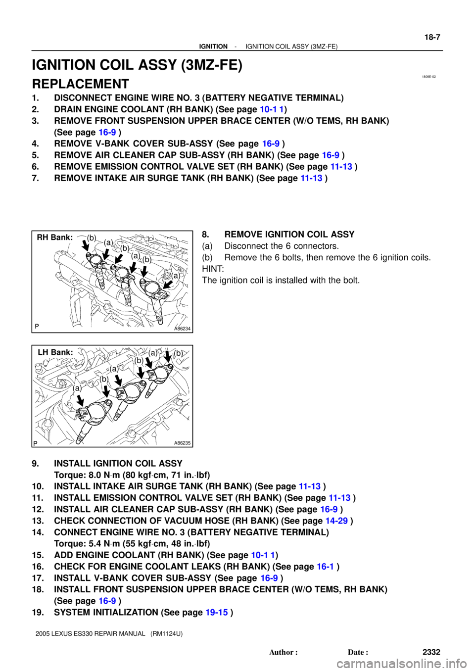
8. REMOVE IGNITION COIL ASSY
(a) Disconnect the 6 connectors.
(b) Remove the 6 bolts, then remove the 6 ignition coils.
HINT:
The ignition coil is installed with the bolt.
9. INSTALL IGNITION COIL ASSY
Torque: 8.0 NVm (80 kgfVcm, 71 in.Vlbf)
10. INSTALL INTAKE AIR SURGE TANK (RH BANK) (See page 11-13)
11. INSTALL EMISSION CONTROL VALVE SET (RH BANK) (See page 11-13)
12. INSTALL AIR CLEANER CAP SUB-ASSY (RH BANK) (See page 16-9)
13. CHECK CONNECTION OF VACUUM HOSE (RH BANK) (See page 14-29)
14. CONNECT ENGINE WIRE NO. 3 (BATTERY NEGATIVE TERMINAL)
Torque: 5.4 NVm (55 kgfVcm, 48 in.Vlbf)
15. ADD ENGINE COOLANT (RH BANK) (See page 10-1 1)
16. CHECK FOR ENGINE COOLANT LEAKS (RH BANK) (See page 16-1)
17. INSTALL V-BANK COVER SUB-ASSY (See page 16-9)
18. INSTALL FRONT SUSPENSION UPPER BRACE CENTER (W/O TEMS, RH BANK)
(See page 16-9)
19. SYSTEM INITIALIZATION (See page 19-15)
Page 868 of 969

RADIATOR CAP INSPECTION ± EG007-05 March 28, 2005
Page 3 of 7
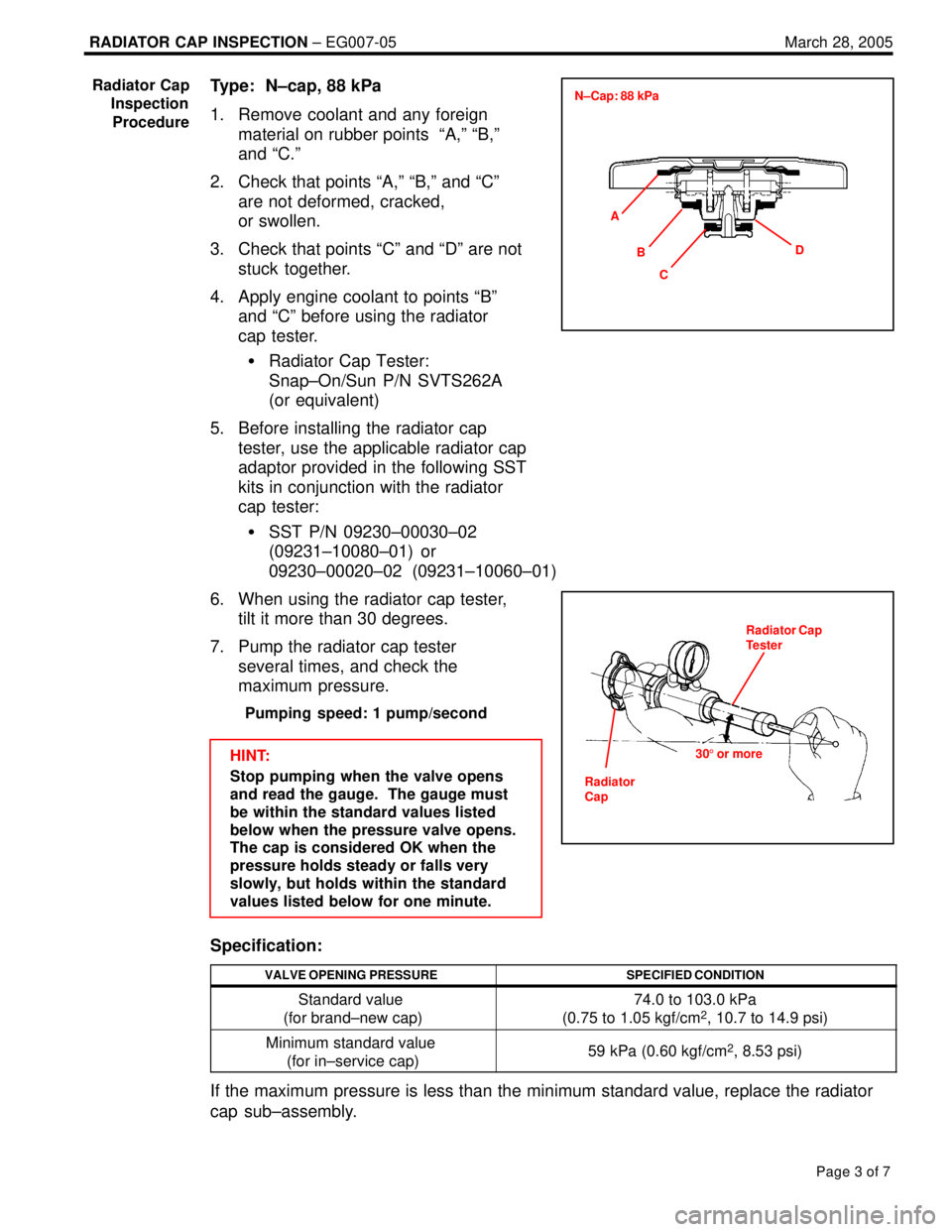
Type: N±cap, 88 kPa
1. Remove coolant and any foreign
material on rubber points ªA,º ªB,º
and ªC.º
2. Check that points ªA,º ªB,º and ªCº
are not deformed, cracked,
or swollen.
3. Check that points ªCº and ªDº are not
stuck together.
4. Apply engine coolant to points ªBº
and ªCº before using the radiator
cap tester.
�Radiator Cap Tester:
Snap±On/Sun P/N SVTS262A
(or equivalent)
5. Before installing the radiator cap
tester, use the applicable radiator cap
adaptor provided in the following SST
kits in conjunction with the radiator
cap tester:
�SST P/N 09230±00030±02
(09231±10080±01) or
09230±00020±02 (09231±10060±01)
6. When using the radiator cap tester,
tilt it more than 30 degrees.
7. Pump the radiator cap tester
several times, and check the
maximum pressure.
Pumping speed: 1 pump/second
HINT:
Stop pumping when the valve opens
and read the gauge. The gauge must
be within the standard values listed
below when the pressure valve opens.
The cap is considered OK when the
pressure holds steady or falls very
slowly, but holds within the standard
values listed below for one minute.
Specification:
VALVE OPENING PRESSURESPECIFIED CONDITION
Standard value
(for brand±new cap)74.0 to 103.0 kPa
(0.75 to 1.05 kgf/cm2, 10.7 to 14.9 psi)
Minimum standard value
(for in±service cap)59 kPa (0.60 kgf/cm2, 8.53 psi)
If the maximum pressure is less than the minimum standard value, replace the radiator
cap sub±assembly.
Radiator Cap
Inspection
Procedure
A
C BD N±Cap: 88 kPa
Radiator Cap
Tester
Radiator
Cap305 or more
Page 869 of 969

RADIATOR CAP INSPECTION ± EG007-05 March 28, 2005
Page 4 of 7
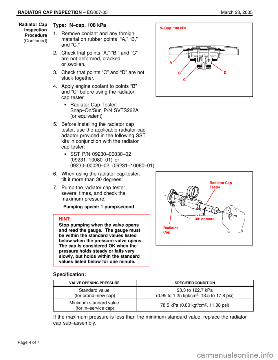
Type: N±cap, 108 kPa
1. Remove coolant and any foreign
material on rubber points ªA,º ªB,º
and ªC.º
2. Check that points ªA,º ªB,º and ªCº
are not deformed, cracked,
or swollen.
3. Check that points ªCº and ªDº are not
stuck together.
4. Apply engine coolant to points ªBº
and ªCº before using the radiator
cap tester.
�Radiator Cap Tester:
Snap±On/Sun P/N SVTS262A
(or equivalent)
5. Before installing the radiator cap
tester, use the applicable radiator cap
adaptor provided in the following SST
kits in conjunction with the radiator
cap tester:
�SST P/N 09230±00030±02
(09231±10080±01) or
09230±00020±02 (09231±10060±01)
6. When using the radiator cap tester,
tilt it more than 30 degrees.
7. Pump the radiator cap tester
several times, and check the
maximum pressure.
Pumping speed: 1 pump/second
HINT:
Stop pumping when the valve opens
and read the gauge. The gauge must
be within the standard values listed
below when the pressure valve opens.
The cap is considered OK when the
pressure holds steady or falls very
slowly, but holds within the standard
values listed below for one minute.
Specification:
VALVE OPENING PRESSURESPECIFIED CONDITION
Standard value
(for brand±new cap)93.3 to 122.7 kPa
(0.95 to 1.25 kgf/cm2, 13.5 to 17.8 psi)
Minimum standard value
(for in±service cap)78.5 kPa (0.80 kgf/cm2, 11.38 psi)
If the maximum pressure is less than the minimum standard value, replace the radiator
cap sub±assembly.
Radiator Cap
Inspection
Procedure
(Continued)
A
C BD N±Cap: 108 kPa
Radiator Cap
Tester
305 or more
Radiator
Cap
Page 870 of 969

RADIATOR CAP INSPECTION ± EG007-05 March 28, 2005
Page 5 of 7
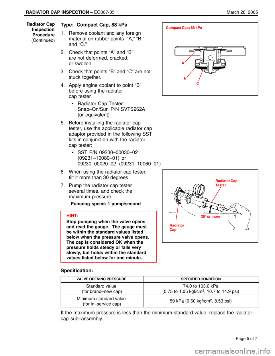
Type: Compact Cap, 88 kPa
1. Remove coolant and any foreign
material on rubber points ªA,º ªB,º
and ªC.º
2. Check that points ªAº and ªBº
are not deformed, cracked,
or swollen.
3. Check that points ªBº and ªCº are not
stuck together.
4. Apply engine coolant to point ªBº
before using the radiator
cap tester.
�Radiator Cap Tester:
Snap±On/Sun P/N SVTS262A
(or equivalent)
5. Before installing the radiator cap
tester, use the applicable radiator cap
adaptor provided in the following SST
kits in conjunction with the radiator
cap tester:
�SST P/N 09230±00030±02
(09231±10080±01) or
09230±00020±02 (09231±10060±01)
6. When using the radiator cap tester,
tilt it more than 30 degrees.
7. Pump the radiator cap tester
several times, and check the
maximum pressure.
Pumping speed: 1 pump/second
HINT:
Stop pumping when the valve opens
and read the gauge. The gauge must
be within the standard values listed
below when the pressure valve opens.
The cap is considered OK when the
pressure holds steady or falls very
slowly, but holds within the standard
values listed below for one minute.
Specification:
VALVE OPENING PRESSURESPECIFIED CONDITION
Standard value
(for brand±new cap)74.0 to 103.0 kPa
(0.75 to 1.05 kgf/cm2, 10.7 to 14.9 psi)
Minimum standard value
(for in±service cap)59 kPa (0.60 kgf/cm2, 8.53 psi)
If the maximum pressure is less than the minimum standard value, replace the radiator
cap sub±assembly.
Radiator Cap
Inspection
Procedure
(Continued)
A
C B Compact Cap: 88 kPa
Radiator Cap
Tester
305 or more
Radiator
Cap