Page 432 of 969

A78727
Seal Packing
Seal Width
4 to 5 mm
(0.16 to 0.20 in.) AA
BB
A78728
Seal PackingSeal Width 3 to 5 mm
(0.12 to 0.20 in.)
A78314
10
1
2
3
4
5
6
78
9 14-56
- ENGINE MECHANICALPARTIAL ENGINE ASSY (3MZ-FE)
2148 Author�: Date�:
2005 LEXUS ES330 REPAIR MANUAL (RM1124U)
(b) Apply a continuous bead of seal packing (Diameter 4 to
5 mm (0.16 to 0.20 in.)) as shown in the illustration.
Seal packing: Part No. 08826-00080 or equivalent
NOTICE:
�Remove any oil from the contact surface.
�Apply seal packing to the inner side of the bolt holes.
�Install the oil pan within 3 minutes after applying seal
packing.
�Do not expose the seal packing to engine oil within 2
hours after installing.
(c) Install the oil pan No. 2 with the 10 bolts and 2 nuts.
Torque: 8.0 NVm (82 kgfVcm, 71 in.Vlbf)
66. INSTALL OIL PAN DRAIN PLUG
(a) Install the drain plug with a new gasket.
Torque: 45 NVm (459 kgfVcm, 33 ftVlbf)
67. INSTALL WATER INLET HOUSING
(a) Remove any old packing material from the contact sur-
face.
(b) Apply a continuous bead of seal packing (Diameter 3 to
5 mm (0.12 to 0.20 in.)) as shown in the illustration.
Seal packing: Part No. 08826-00100 or equivalent
NOTICE:
�Remove any oil from the contact surface.
�Install the water inlet housing within 3 minutes after
applying seal packing.
�Do not expose the seal packing to coolant within 2
hours after installing.
(c) Install the water inlet housing with the 8 bolts and 2 nuts.
Using several steps, tighten the bolts and nuts uniformly
in the sequence shown in the illustration.
Torque: 8.0 NVm (82 kgfVcm, 71 in.Vlbf)
Page 443 of 969

A78703
SST
A78704
SST
- ENGINE MECHANICALPARTIAL ENGINE ASSY (3MZ-FE)
14-67
2159 Author�: Date�:
2005 LEXUS ES330 REPAIR MANUAL (RM1124U)
(b) Using SST, tighten the RH pulley bolt.
SST 09960-10010 (09962-01000, 09963-01000)
Torque: 125 NVm (1,275 kgfVcm, 92 ftVlbf)
(c) Using SST, tighten the LH pulley bolt.
SST 09960-10010 (09962-01000, 09963-01000)
Torque: 125 NVm (1,275 kgfVcm, 92 ftVlbf)
87. INSTALL TIMING BELT IDLER SUB-ASSY NO.2
Torque: 43 NVm (438 kgfVcm, 32 ftVlbf)
88. INSTALL TIMING BELT IDLER SUB-ASSY NO.1
(a) Using a socket hexagon wrench 10, install the plate washer and timing belt idler No. 1 with the pivot
bolt.
Torque: 34 NVm (347 kgfVcm, 25 ftVlbf)
89. INSTALL TIMING BELT
(a) Remove any oil or water on the pulleys, then keep them
clean.
NOTICE:
�If there is a trace of water and/or oil on the timing belt,
repair the leakage and install a new timing belt.
�Only wipe the pulleys; do not use any cleaning agent.
(b) Check the idler pulleys.
(1) Check that the idler pulley turns smoothly.
(2) Visually check the seal portion of the idler pulley for
oil leakage.
(c) Check the water pump.
(1) Turn the pulley, then check that water pump bearing
moves smoothly and does not make a noise.
(2) Visually check the drain hole for coolant leakage.
(d) Temporarily install the crankshaft pulley bolt and washer
to the crankshaft.
Page 458 of 969

EM3336
14-82
- ENGINE MECHANICALTIMING BELT (3MZ-FE)
2174 Author�: Date�:
2005 LEXUS ES330 REPAIR MANUAL (RM1124U)
14. INSPECT TIMING BELT
NOTICE:
�Do not bend, twist or turn the timing belt inside out.
�Do not allow contact of the timing belt with oil, water
or steam.
�Do not use the timing belt tension when installing or
removing the mounting bolt of the camshaft timing
pulley.
Check the belt for any defects as shown in the illustrations.
Also, check these points below.
(a) If the belt tears in a short time:
�Check if the belt is installed properly.
�Check if the timing cover gasket is damaged and if
it is installed properly.
(b) If the belt teeth are cracked or damaged, check if either
camshaft is locked.
(c) If there is noticeable wear or cracks on the belt face,
check if there are nicks on the side of the idler pulley lock
and water pump.
(d) If there is wear or damage on only one side of the belt,
check the belt guide and alignment of each pulley.
(e) If there is noticeable wear on the belt teeth:
�Check the timing cover for damage.
�Check that the gasket has been installed correctly.
�Check for foreign objects on the pulley teeth.
If there is any doubt about the belt condition, replace the timing
belt.
15. INSTALL TIMING BELT
(a) Remove any oil or water on the pulleys, then keep them
clean.
NOTICE:
�If there is a trace of water and/or oil on the timing belt,
repair the leakage and install a new timing belt.
�Only wipe the pulleys; do not use any cleaning agent.
(b) Check the idler pulleys.
(1) Check that the idler pulley turns smoothly.
(2) Visually check the seal portion of the idler pulley for
oil leakage.
(c) Check the water pump.
(1) Turn the pulley, then check that water pump bearing
moves smoothly and does not make a noise.
(2) Visually check the drain hole for coolant leakage.
(d) Temporarily install the crankshaft pulley bolt and washer
to the crankshaft.
Page 469 of 969

141JD-01
A78761
RH:
SST
A78762
SSTLH:
- ENGINE MECHANICALCAMSHAFT (RH BANK) (3MZ-FE)
14-93
2185 Author�: Date�:
2005 LEXUS ES330 REPAIR MANUAL (RM1124U)
REPLACEMENT
1. DISCONNECT BATTERY NEGATIVE TERMINAL
2. DRAIN ENGINE COOLANT (See page 16-9)
3. REMOVE FRONT WHEEL RH
4. REMOVE FRONT SUSPENSION UPPER BRACE CENTER (W/O TEMS) (See page 10-1 1)
5. REMOVE V-BANK COVER SUB-ASSY (See page 10-1 1)
6. REMOVE AIR CLEANER CAP SUB-ASSY (See page 10-1 1)
7. REMOVE EMISSION CONTROL VALVE SET (See page 11-13)
8. REMOVE INTAKE AIR SURGE TANK (See page 11-13)
9. REMOVE IGNITION COIL ASSY
10. REMOVE CYLINDER HEAD COVER SUB-ASSY (See page 14-7)
11. REMOVE FRONT FENDER APRON SEAL RH
12. REMOVE V (COOLER COMPRESSOR TO CRANKSHAFT PULLEY) BELT NO.1
(See page 14-5)
13. REMOVE VANE PUMP V BELT (See page 14-5)
14. REMOVE ENGINE MOVING CONTROL ROD (See page 14-79)
15. REMOVE ENGINE MOUNTING STAY NO.2 RH (See page 14-79)
16. REMOVE GENERATOR BRACKET NO.2 (See page 14-79)
17. REMOVE CRANKSHAFT PULLEY (See page 14-79)
SST 09213-54015 (91651-60855), 09330-00021, 09950-50013 (09951-05010, 09952-05010,
09953-05020, 09954-05031)
18. REMOVE TIMING BELT NO.1 COVER
19. REMOVE TIMING BELT NO.2 COVER (See page 14-79)
20. REMOVE ENGINE MOUNTING BRACKET RH (See page 14-79)
21. REMOVE TIMING BELT GUIDE NO.2
22. REMOVE TIMING BELT (See page 14-79)
23. REMOVE TIMING BELT IDLER SUB-ASSY NO.2
24. REMOVE CAMSHAFT TIMING PULLEY
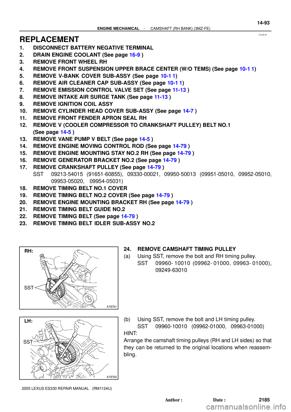
(a) Using SST, remove the bolt and RH timing pulley.
SST 09960- 10010 (09962- 01000, 09963- 01000),
09249-63010
(b) Using SST, remove the bolt and LH timing pulley.
SST 09960-10010 (09962-01000, 09963-01000)
HINT:
Arrange the camshaft timing pulleys (RH and LH sides) so that
they can be returned to the original locations when reassem-
bling.
Page 478 of 969
14-102
- ENGINE MECHANICALCAMSHAFT (RH BANK) (3MZ-FE)
2194 Author�: Date�:
2005 LEXUS ES330 REPAIR MANUAL (RM1124U)
55. INSTALL INTAKE AIR SURGE TANK (See page 11-13)
56. INSTALL EMISSION CONTROL VALVE SET (See page 11-13)
57. INSTALL AIR CLEANER CAP SUB-ASSY (See page 10-1 1)
58. CHECK CONNECTION OF VACUUM HOSE (See page 14-29)
59. INSTALL V-BANK COVER SUB-ASSY (See page 10-1 1)
60. INSTALL FRONT SUSPENSION UPPER BRACE CENTER (W/O TEMS) (See page 10-1 1)
61. INSTALL FRONT WHEEL RH (See page 14-5)
62. ADD ENGINE COOLANT (See page 16-9)
63. CHECK FOR ENGINE COOLANT LEAKS (See page 16-1)
64. SYSTEM INITIALIZATION (See page 19-15)
Page 483 of 969

141JF-01
A78710Align
- ENGINE MECHANICALCAMSHAFT (LH BANK) (3MZ-FE)
14-107
2199 Author�: Date�:
2005 LEXUS ES330 REPAIR MANUAL (RM1124U)
REPLACEMENT
1. DISCONNECT BATTERY NEGATIVE TERMINAL
2. DRAIN ENGINE COOLANT (See page 16-9)
3. REMOVE FRONT WHEEL RH
4. REMOVE V-BANK COVER SUB-ASSY (See page 10-1 1)
5. REMOVE RADIATOR HOSE INLET
6. REMOVE IGNITION COIL ASSY
7. REMOVE CYLINDER HEAD COVER SUB-ASSY LH (See page 14-7)
8. REMOVE FRONT FENDER APRON SEAL RH
9. REMOVE V (COOLER COMPRESSOR TO CRANKSHAFT PULLEY) BELT NO.1
(See page 14-5)
10. REMOVE VANE PUMP V BELT (See page 14-5)
11. REMOVE ENGINE MOVING CONTROL ROD (See page 14-79)
12. REMOVE ENGINE MOUNTING STAY NO.2 RH (See page 14-79)
13. REMOVE GENERATOR BRACKET NO.2 (See page 14-79)
14. REMOVE CRANKSHAFT PULLEY (See page 14-79)
SST 09213-54015 (91651-60855), 09330-00021, 09950-50013 (09951-05010, 09952-05010,
09953-05020, 09954-05031)
15. REMOVE TIMING BELT NO.1 COVER
16. REMOVE TIMING BELT NO.2 COVER (See page 14-79)
17. REMOVE ENGINE MOUNTING BRACKET RH (See page 14-79)
18. REMOVE TIMING BELT GUIDE NO.2
19. REMOVE TIMING BELT (See page 14-79)
20. REMOVE TIMING BELT IDLER SUB-ASSY NO.2
21. REMOVE CAMSHAFT TIMING PULLEY (See page 14-93)
SST 09960-10010 (09962-01000, 09963-01000), 09249-63010
22. REMOVE TIMING BELT NO.3 COVER (See page 14-93)
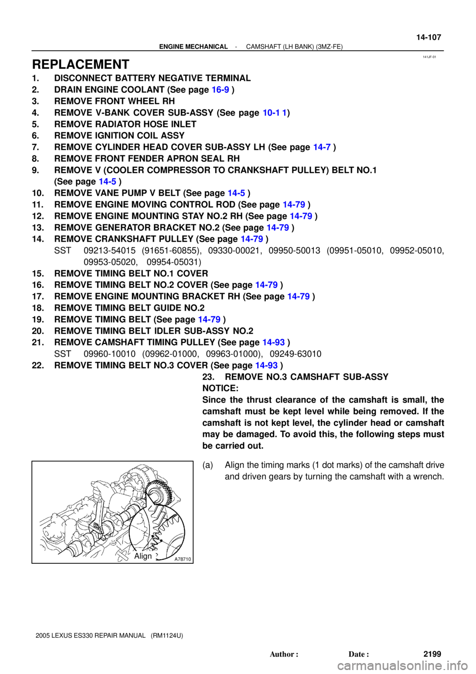
23. REMOVE NO.3 CAMSHAFT SUB-ASSY
NOTICE:
Since the thrust clearance of the camshaft is small, the
camshaft must be kept level while being removed. If the
camshaft is not kept level, the cylinder head or camshaft
may be damaged. To avoid this, the following steps must
be carried out.
(a) Align the timing marks (1 dot marks) of the camshaft drive
and driven gears by turning the camshaft with a wrench.
Page 487 of 969

- ENGINE MECHANICALCAMSHAFT (LH BANK) (3MZ-FE)
14-1 11
2203 Author�: Date�:
2005 LEXUS ES330 REPAIR MANUAL (RM1124U)
34. INSPECT TIMING BELT (See page 14-79)
35. INSTALL TIMING BELT (See page 14-79)
SST 09960-10010 (09962-01000, 09963-01000)
36. INSTALL TIMING BELT TENSIONER ASSY (See page 14-79)
37. INSTALL TIMING BELT GUIDE NO.2 (See page 14-79)
38. INSTALL ENGINE MOUNTING BRACKET RH (See page 14-79)
39. INSTALL TIMING BELT NO.2 COVER (See page 14-79)
40. INSTALL TIMING BELT NO.1 COVER (See page 14-79)
41. INSTALL CRANKSHAFT PULLEY (See page 14-79)
SST 09213-54015 (91651-60855), 09330-00021
42. INSTALL GENERATOR BRACKET NO.2 (See page 14-79)
43. INSTALL ENGINE MOUNTING STAY NO.2 RH (See page 14-79)
44. INSTALL ENGINE MOVING CONTROL ROD (See page 14-79)
45. INSPECT VALVE CLEARANCE (See page 14-7)
46. ADJUST VALVE CLEARANCE (See page 14-7)
SST 09248-55040 (09248-05410, 09248-05420)
47. INSTALL VANE PUMP V BELT (See page 14-5)
48. INSTALL V (COOLER COMPRESSOR TO CRANKSHAFT PULLEY) BELT NO.1
(See page 14-5)
49. INSPECT DRIVE BELT DEFLECTION AND TENSION (See page 14-1)
50. INSTALL CYLINDER HEAD COVER SUB-ASSY LH (See page 14-7)
51. INSTALL IGNITION COIL ASSY (See page 14-7)
52. INSTALL V-BANK COVER SUB-ASSY (See page 10-1 1)
53. INSTALL FRONT WHEEL RH (See page 14-5)
54. ADD ENGINE COOLANT (See page 16-9)
55. CHECK FOR ENGINE COOLANT LEAKS (See page 16-1)
56. SYSTEM INITIALIZATION (See page 19-15)
Page 490 of 969
A86583� Non-reusable part
: Specified torqueN´m (kgf´cm, ft´lbf)� Intake Manifold
to Head Gasket No. 2� Intake Manifold
to Head Gasket No. 1
Radiator Hose InletWater Outlet
Heater Inlet
Water Hose Intake Manifold Ground Cable
Washer
8.4 (86, 74 in.Vlbf)
x2x9
x2
Washer
15 (153, 11)
15 (153, 11)
Fuel Pipe
Clamp
15 (153, 11)
Fuel Injector
Connector
Clamp
Fuel Injector Connector
x2
Engine Coolant
Temperature Sensor
Connector
Bond Cable No. 1
Connector
Pipe
14-1 14
- ENGINE MECHANICALCYLINDER HEAD GASKET (3MZ-FE)
2206 Author�: Date�:
2005 LEXUS ES330 REPAIR MANUAL (RM1124U)