Page 582 of 969

2030 Author�: Da")
B00679
B00347
New O-ring
Delivery Pipe
InjectorCORRECT
WRONG
Grommet
FI6372
A62371
Delivery Pipe
Spacer
InsulatorO-ring
Grommet
A60083
Fuel Pipe
Clamp
11-2
- FUELFUEL SYSTEM (3MZ-FE)
2030 Author�: Date�:
2005 LEXUS ES330 REPAIR MANUAL (RM1124U)
(4) In order to prevent the disconnected fuel pump tube
from being damaged and foreign objects from being
introduced, cover the disconnected fuel pump tube
with a vinyl or plastic bag.
(5) Place a tray under the vehicle or point of disconnec-
tion to catch any fuel that may spill.
(6) Put a container under the connection.
(b) Take the following precautions when removing and instal-
ling the fuel injectors.
NOTICE:
Never reuse the O-ring.
(1) When installing a new O-ring on the fuel injector, be
careful not to damage it.
(2) Coat a new O-ring with spindle oil or gasoline be-
fore installing. Never use engine oil, gear oil or
brake oil.
(c) Install the fuel injector to the fuel delivery pipe and intake
manifold as shown in the illustration. Before installing the
fuel injector, be sure to apply spindle oil or gasoline to the
place where the fuel delivery pipe or intake manifold
touches the O-ring of the fuel injector.
(d) Take the following precautions when disconnecting the
quick connector.
(1) Remove the fuel pipe clamp.
(2) Check the pipe and around the quick connector for
dirt or mud before disconnecting them. Remove the
dirt if necessary.
Page 583 of 969

11-3
2031 Author�: Date�:
2005 LEXUS ES330 REPAIR MANUAL (RM1124U)
(3) Disconnect the quick connector from the p")
A
A
B12941
B12944
Vinyl Bag
A52581
A71366
Push
A71366
Pull
- FUELFUEL SYSTEM (3MZ-FE)
11-3
2031 Author�: Date�:
2005 LEXUS ES330 REPAIR MANUAL (RM1124U)
(3) Disconnect the quick connector from the pipe while
pinching portion A with your fingers as shown in the
illustration.
(4) If the quick connector and pipe are stuck, pinch the
pipe, then push and pull the quick connector to re-
lease and pull it out.
NOTICE:
Do not use any tools.
(5) If there is dirt or any other substances on the sealing
surface that might interfere with the seal, clean the
area thoroughly before assembling.
(6) In order to prevent the disconnected pipe and quick
connector from damage or dirt, cover them with a vi-
nyl or plastic bag.
(e) Take the following precautions when connecting the quick
connector.
(1) Check the connected part of the pipe for damage or
foreign objects.
(2) Align the axis of the quick connector with the axis of
the pipe, then push into the quick connector until the
quick connector makes a ºclickº sound. In case that
the connection is tight, apply a little amount of fresh
engine oil to the tip of the pipe.
(3) After connecting, check if the pipe and quick con-
nector are securely connected by pulling on them.
(4) Install the fuel pipe clamp.
(5) Check if there is any leakage.
Page 585 of 969
110XS-01
Fuel Tube Connector
A50710
A60083
Fuel Pipe
Clamp
A
A
B12941
- FUELFUEL SYSTEM (3MZ-FE)
11-5
2033 Author�: Date�:
2005 LEXUS ES330 REPAIR MANUAL (RM1124U)
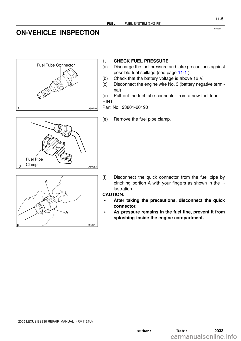
ON-VEHICLE INSPECTION
1. CHECK FUEL PRESSURE
(a) Discharge the fuel pressure and take precautions against
possible fuel spillage (see page 11-1).
(b) Check that tha battery voltage is above 12 V.
(c) Disconnect the engine wire No. 3 (battery negative termi-
nal).
(d) Pull out the fuel tube connector from a new fuel tube.
HINT:
Part No. 23801-20190
(e) Remove the fuel pipe clamp.
(f) Disconnect the quick connector from the fuel pipe by
pinching portion A with your fingers as shown in the il-
lustration.
CAUTION:
�After taking the precautions, disconnect the quick
connector.
�As pressure remains in the fuel line, prevent it from
splashing inside the engine compartment.
Page 586 of 969

SST
(Hose)
Fuel Tube
Connector
Fuel Inlet Tube
SST
(Hose)
A86347DLC3
Hand-held Tester
11-6
- FUELFUEL SYSTEM (3MZ-FE)
2034 Author�: Date�:
2005 LEXUS ES330 REPAIR MANUAL")
A71359
SSTSST
(T-joint)
SST
(Hose)
Fuel Tube
Connector
Fuel Inlet Tube
SST
(Hose)
A86347DLC3
Hand-held Tester
11-6
- FUELFUEL SYSTEM (3MZ-FE)
2034 Author�: Date�:
2005 LEXUS ES330 REPAIR MANUAL (RM1124U)
(g) Install SST (a pressure gauge) and fuel tube connector
using SST as shown in the illustration.
SST 09268-41047 (95336-08070), 09268-45014
(09268-41250, 09268-41200, 09268-41220)
(h) Wipe up any gasoline.
(i) Reconnect the engine wire No. 3 (battery negative termi-
nal).
(j) Connect the hand-hand tester to the DLC3.
(k) Measure the fuel pressure.
Fuel pressure:
304 to 343 kPa (3.1 to 3.5 kgf/cm
2, 44 to 50 psi)
If the pressure is high, replace the fuel pressure regulator.
If the pressure is low, check the fuel hose connections, fuel
pump, fuel filter and fuel pressure regulator.
(l) Disconnect the hand-held tester from the DLC3.
(m) Start the engine.
(n) Measure the fuel pressure at idle.
Fuel pressure:
304 to 343 kPa (3.1 to 3.5 kgf/cm
2, 44 to 50 psi)
(o) Stop the engine.
(p) Check that the fuel pressure remains as specified for 5
minutes after the engine has stopped.
Fuel pressure: 147 kPa (1.5 kgf/cm
2, 21 psi) or more
If the pressure is not as specified, check the fuel pump, pres-
sure regulator and/or fuel injectors.
(q) After checking the fuel pressure, disconnect the battery
negative terminal and carefully remove SST and the fuel
tube connector to prevent gasoline splash.
(r) Reconnect the No. 1 fuel pipe (the fuel tube connector).
CAUTION:
After taking the precautions, connect the quick connector.
Page 587 of 969

11-7
2035 Author�: Date�:
2005 LEXUS ES330 REPAIR MANUAL (RM1124U)
2. CHECK FUEL PUMP OPERATION AND FUEL LEAK
(a) When using the")
A86347DLC3
Hand-held Tester
A62390
FP
+B
- FUELFUEL SYSTEM (3MZ-FE)
11-7
2035 Author�: Date�:
2005 LEXUS ES330 REPAIR MANUAL (RM1124U)
2. CHECK FUEL PUMP OPERATION AND FUEL LEAK
(a) When using the hand-held tester.
(1) Connect the hand-held tester to the DLC3.
(2) Turn the ignition switch ON and the hand-held tes-
ter ON.
NOTICE:
Do not start the engine.
(3) Select the ACTIVE TEST mode on the hand-held
tester.
(4) If you need help to select the ACTIVE TEST mode
on the hand-held tester, refer to the hand-held tes-
ter operator's manual.
(b) When not using the hand-held tester.
(1) Remove the circuit opening relay.
(2) Using a service wire, connect terminals FP and +B
of the engine room relay block.
NOTICE:
Pay due attention to the terminal connecting position to
avoid a malfunction.
(3) Turn the ignition switch ON, and check that the fuel
pump operates.
NOTICE:
Do not start the engine.
(c) Check that there are no fuel leaks after doing mainte-
nance anywhere on the fuel system.
Page 591 of 969
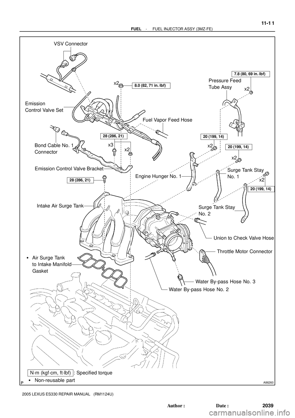
A86260� Non-reusable part
: Specified torque VSV Connector
8.0 (82, 71 in.Vlbf)x2
Emission
Control Valve Set
Emission Control Valve Bracket
Intake Air Surge Tank
� Air Surge Tank
to Intake Manifold
Gasket
Throttle Motor Connector
Water By-pass Hose No. 3
Water By-pass Hose No. 2
N´m (kgf´cm, ft´lbf)
Union to Check Valve Hose
Fuel Vapor Feed Hose
x2 x3
Engine Hunger No. 1Surge Tank Stay
No. 1
Surge Tank Stay
No. 2
20 (199, 14)
20 (199, 14)
20 (199, 14)
7.8 (80, 69 in.Vlbf)
x2
x2 Pressure Feed
Tube Assy
28 (286, 21)
x2
x2
Bond Cable No. 1
Connector
28 (286, 21)
- FUELFUEL INJECTOR ASSY (3MZ-FE)
11-1 1
2039 Author�: Date�:
2005 LEXUS ES330 REPAIR MANUAL (RM1124U)
Page 593 of 969
(a)
(a)
A86300(c)
(e)
(e)(f)
(d)
(g)
(g)
A86297
(b)
(a)
(c)
(d)
A79706
(e)
- FUELFUEL INJECTOR ASSY (3MZ-FE)
11-13
2041 Author�: Date�:
2005 LEXUS ES330 REPAIR MANUAL (RM1124U)
RE")
110XV-01
A79751
(b)(a)
(a)
A86300(c)
(e)
(e)(f)
(d)
(g)
(g)
A86297
(b)
(a)
(c)
(d)
A79706
(e)
- FUELFUEL INJECTOR ASSY (3MZ-FE)
11-13
2041 Author�: Date�:
2005 LEXUS ES330 REPAIR MANUAL (RM1124U)
REPLACEMENT
1. DISCHARGE FUEL SYSTEM PRESSURE (See page 11-1)
2. DISCONNECT ENGINE WIRE NO. 3 (BATTERY NEGATIVE TERMINAL)
3. DRAIN ENGINE COOLANT (See page 16-9)
4. REMOVE FRONT SUSPENSION UPPER BRACE CENTER (W/O TEMS) (See page 10-1 1)
5. REMOVE V-BANK COVER SUB-ASSY (See page 10-1 1)
6. REMOVE AIR CLEANER CAP SUB-ASSY (See page 10-1 1)
7. REMOVE EMISSION CONTROL VALVE SET
(a) Disconnect the 2 VSV connectors.
(b) Remove the wire harness clamp.
(c) Disconnect the fuel vapor feed hose No. 1.
(d) Disconnect the fuel vapor feed hose No. 2.
(e) Disconnect the 2 vacuum hoses.
(f) Remove the clamp.
(g) Remove the 2 nuts, then remove the emission control
valve set.
8. REMOVE INTAKE AIR SURGE TANK
(a) Disconnect the throttle motor connector.
(b) Disconnect the water by-pass hose No. 3.
(c) Disconnect the water by-pass hose No. 2.
(d) Disconnect the union to check valve hose.
(e) Disconnect the ventilation hose.
Page 594 of 969

(f)
A86299
(g)
(g)
(i)
(h)
(h)
(i)
A86301
(l)
(k)(k)
(k)(l)
(k)
(i)
A79710
(a)
(b)(c)
A86302
(a)(a)
(a)
(a)
(a)
(a) 11-14
- FUELFUEL INJECTOR ASSY (3MZ-FE)
2042 Author�: Date�:
2005 LEXUS E")
A86298
(f)
(f)
A86299
(g)
(g)
(i)
(h)
(h)
(i)
A86301
(l)
(k)(k)
(k)(l)
(k)
(i)
A79710
(a)
(b)(c)
A86302
(a)(a)
(a)
(a)
(a)
(a) 11-14
- FUELFUEL INJECTOR ASSY (3MZ-FE)
2042 Author�: Date�:
2005 LEXUS ES330 REPAIR MANUAL (RM1124U)
(f) Remove the 2 nuts, then remove the pressure feed tube.
(g) Remove the 2 bolts, then remove the engine hunger No.
1.
(h) Remove the 2 bolts, then remove the surge tank stay No.
1.
(i) Remove the 2 bolts, then remove the surge tank stay No.
2.
(j) Disconnect the bond cable No. 1 connector.
(k) Using a socket hexagon wrench 8, remove the 4 bolts.
(l) Remove the 2 nuts, then remove the emission control
valve bracket and intake air surge tank.
(m) Remove the gasket from the intake air surge tank.
9. SEPARATE FUEL PIPE SUB-ASSY NO.1
(a) Remove the fuel pressure pulsation damper and 2 gas-
kets.
(b) Remove the fuel pipe No. 2 union bolt and 2 gaskets.
(c) Remove the bolt, then separate the fuel pipe No. 1.
10. REMOVE FUEL INJECTOR ASSY
(a) Disconnect the 6 fuel injector connectors.