Page 574 of 969
A86265
(c)
(d)
(d)
(d)
(d)
(d)(d)
A862661 2
3 4
75
68
9 10
11
A86267
(a)
(b)
(c)
- ENGINE CONTROL SYSTEMKNOCK SENSOR (3MZ-FE)
10-17
2022 Author�: Date�:
2005 LEXUS ES330 REPAIR MANUAL (RM1124U)
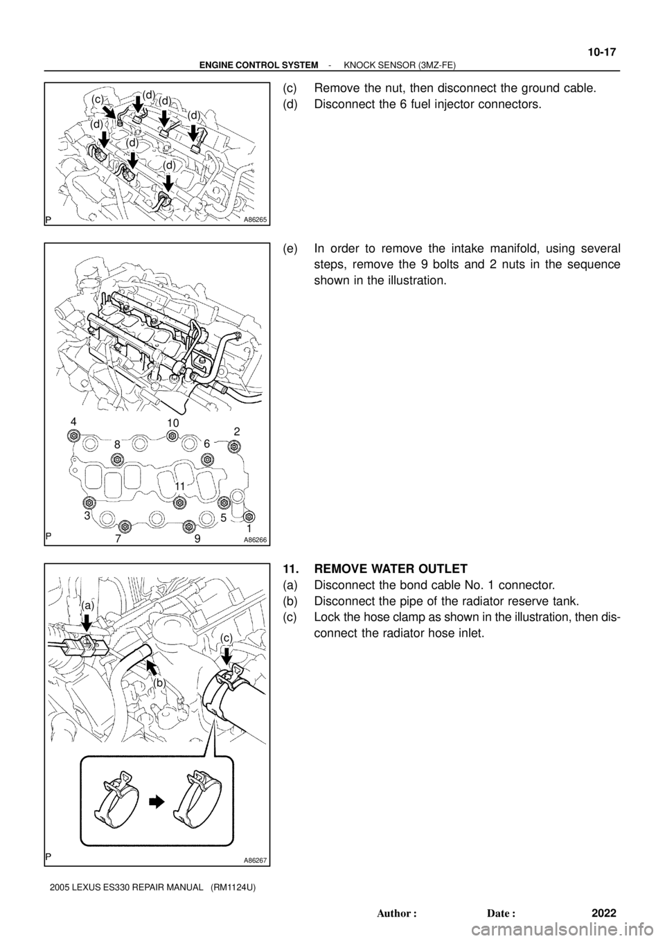
(c) Remove the nut, then disconnect the ground cable.
(d) Disconnect the 6 fuel injector connectors.
(e) In order to remove the intake manifold, using several
steps, remove the 9 bolts and 2 nuts in the sequence
shown in the illustration.
11. REMOVE WATER OUTLET
(a) Disconnect the bond cable No. 1 connector.
(b) Disconnect the pipe of the radiator reserve tank.
(c) Lock the hose clamp as shown in the illustration, then dis-
connect the radiator hose inlet.
Page 575 of 969

(e)
(f)
(f)
(f)
(f)
(g)
A79749
(a)
(b)
(a)
(b)
A79750
Upper
Engine
Front0 to 5� 10-18
- ENGINE CONTROL SYSTEMKNOCK SENSOR (3MZ-FE)
2023 Author�: Date�:
2005 LEXUS ES330 REPAIR MANUAL (RM")
A86268
(d)
(e)
(f)
(f)
(f)
(f)
(g)
A79749
(a)
(b)
(a)
(b)
A79750
Upper
Engine
Front0 to 5� 10-18
- ENGINE CONTROL SYSTEMKNOCK SENSOR (3MZ-FE)
2023 Author�: Date�:
2005 LEXUS ES330 REPAIR MANUAL (RM1124U)
(d) Disconnect the engine coolant temperature sensor con-
nector.
(e) Remove the clamp.
(f) Remove the 2 bolts, 2 nuts and 2 washers.
(g) Lock the hose clamp as shown in the illustration. Then re-
move the water outlet together with water by-pass hose
No. 1.
(h) Remove the 2 gaskets from the 2 cylinder heads.
12. REMOVE KNOCK SENSOR
(a) Disconnect the 2 knock sensor connectors.
(b) Remove the 2 nuts, then remove the 2 knock sensors.
13. INSTALL KNOCK SENSOR
(a) Install the 2 knock sensors with the 2 nuts as shown in the
illustration.
Torque: 20 NVm (204 kgfVcm, 14 ftVlbf)
(b) Connect the 2 knock sensor connectors.
14. INSTALL WATER OUTLET
(a) Install 2 new gaskets to the 2 cylinder heads.
(b) Install the water outlet together with water by-pass hose No. 1, then unlock the hose clamp.
(c) Tighten the 2 bolts, 2 nuts and 2 washers.
Torque: 15 NVm (153 kgfVcm, 11 ftVlbf)
(d) Install the clamp.
(e) Connect the engine coolant temperature sensor connector.
(f) Connect the bond cable No. 3 connector.
(g) Connect the pipe of the radiator reserve tank.
(h) Connect the radiator hose inlet, then unlock the hose clamp.
Page 576 of 969

10-19
2024 Author�: Date�:
2005 LEXUS ES330 REPAIR MANUAL (RM1124U)
15. INSTALL")
A8626611 10
9 8
5
7
64
3 2
1
A86269
Push
Fuel Pipe
Clamp
A86262
A
B
B
B
- ENGINE CONTROL SYSTEMKNOCK SENSOR (3MZ-FE)
10-19
2024 Author�: Date�:
2005 LEXUS ES330 REPAIR MANUAL (RM1124U)
15. INSTALL INTAKE MANIFOLD
(a) Install the intake manifold with the 9 bolts, 2 nuts and 2
washers. Using several steps, tighten the 9 bolts and 2
nuts uniformly in the sequence shown in the illustration.
Torque: 15 NVm (153 kgfVcm, 11 ftVlbf)
(b) Retighten the 9 water outlet mounting bolts and 2 nuts.
Torque: 15 NVm (153 kgfVcm, 11 ftVlbf)
(c) Install the ground cable with the nut.
Torque: 8.4 NVm (86 kgfVcm, 74 in.Vlbf)
(d) Connect the heater inlet water hose.
(e) Connect the fuel pipe No. 1.
(1) Push in the quick connector to the pipe until it
makes a ºclickº sound.
NOTICE:
�Check the connected part for damage or foreign ob-
jects.
�After connecting, check if the quick connector and
pipe are securely connected by pulling them.
(2) Install the fuel pipe clamp.
16. INSTALL ENGINE MOVING CONTROL ROD
Torque:
23 NVm (235 kgfVcm, 17 ftVlbf) for bolt A
64 NVm (653 kgfVcm, 47 ftVlbf) for bolt B
17. INSTALL INTAKE AIR SURGE TANK (See page 11-13)
18. INSTALL EMISSION CONTROL VALVE SET (See page 11-13)
19. INSTALL AIR CLEANER CAP SUB-ASSY (See page 10-1 1)
20. CHECK CONNECTION OF VACUUM HOSE (See page 14-29)
21. CONNECT ENGINE WIRE NO. 3 (BATTERY NEGATIVE TERMINAL)
Torque: 5.4 NVm (55 kgfVcm, 48 in.Vlbf)
22. ADD ENGINE COOLANT (See page 16-9)
23. CHECK FOR ENGINE COOLANT LEAKS (See page 16-1)
24. CHECK FOR FUEL LEAKS (See page 11-5)
25. INSTALL V-BANK COVER SUB-ASSY (See page 10-1 1)
Page 577 of 969
10-20
- ENGINE CONTROL SYSTEMKNOCK SENSOR (3MZ-FE)
2025 Author�: Date�:
2005 LEXUS ES330 REPAIR MANUAL (RM1124U)
26. INSTALL FRONT SUSPENSION UPPER BRACE CENTER (W/O TEMS) (See page 10-1 1)
27. SYSTEM INITIALIZATION (See page 19-15)
Page 578 of 969
100J8-01
A86338
(a)
(b)
(b)
- ENGINE CONTROL SYSTEMACCELERATOR PEDAL ASSY (3MZ-FE (NORMAL
PEDAL))10-21
2026 Author�: Date�:
2005 LEXUS ES330 REPAIR MANUAL (RM1124U)
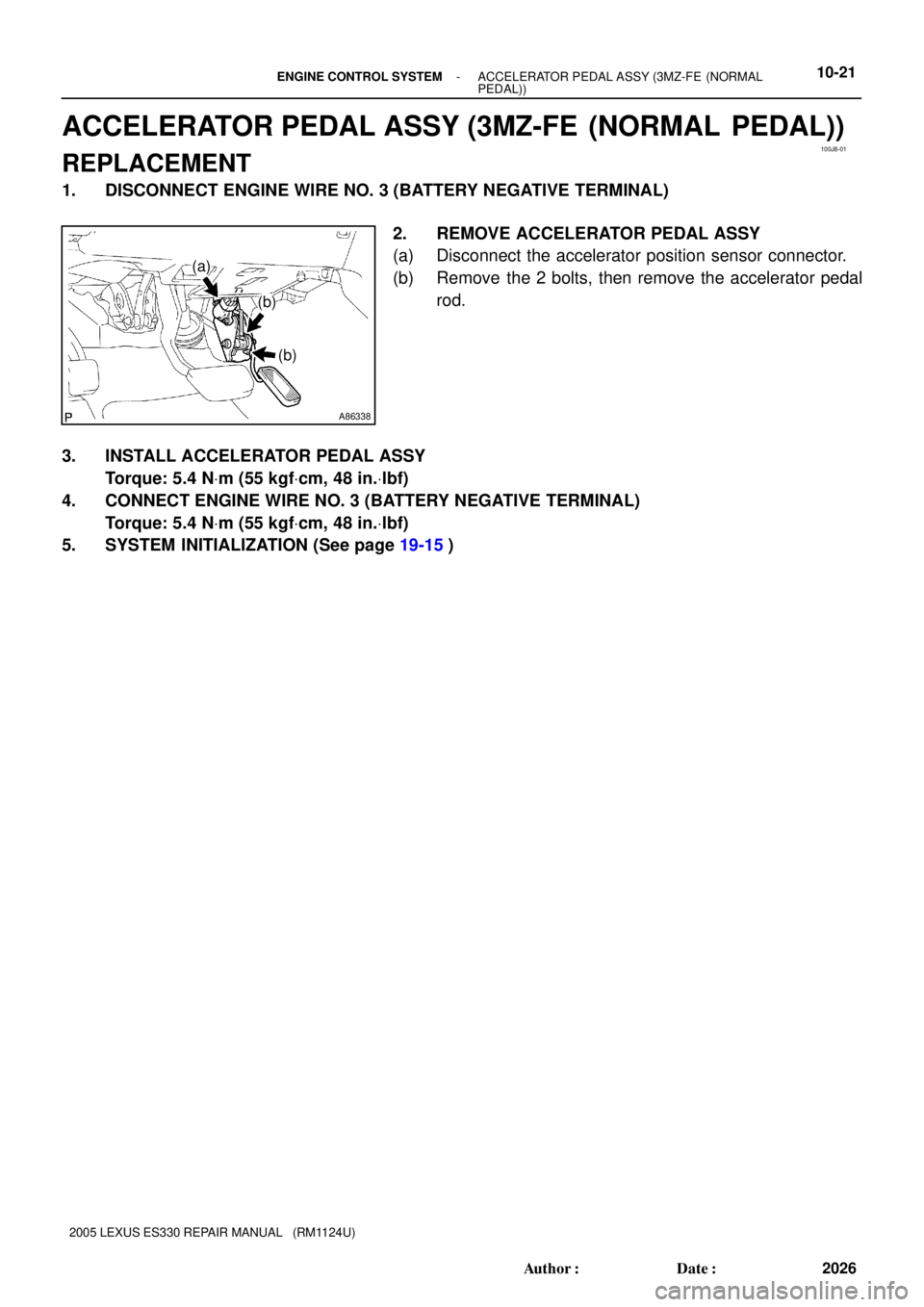
ACCELERATOR PEDAL ASSY (3MZ-FE (NORMAL PEDAL))
REPLACEMENT
1. DISCONNECT ENGINE WIRE NO. 3 (BATTERY NEGATIVE TERMINAL)
2. REMOVE ACCELERATOR PEDAL ASSY
(a) Disconnect the accelerator position sensor connector.
(b) Remove the 2 bolts, then remove the accelerator pedal
rod.
3. INSTALL ACCELERATOR PEDAL ASSY
Torque: 5.4 NVm (55 kgfVcm, 48 in.Vlbf)
4. CONNECT ENGINE WIRE NO. 3 (BATTERY NEGATIVE TERMINAL)
Torque: 5.4 NVm (55 kgfVcm, 48 in.Vlbf)
5. SYSTEM INITIALIZATION (See page 19-15)
Page 579 of 969
100J9-02
A86255
(a)
(b)
(a)
(b)(a)
A86256
(b)
(a)
(b)
(b)
(b)
(b)
(c)
(c)
A86257
(a)
(a)
A86258
(a)
(a) 10-22
- ENGINE CONTROL SYSTEMECM (3MZ-FE)
2027 Author�: Date�:
2005 LEXUS ES330 REPAIR MANUAL (RM1124U)
ECM (3MZ-FE)
REPLACEMENT
1. DISCONNECT ENGINE WIRE NO. 3 (BATTERY NEGATIVE TERMINAL)
2. REMOVE FRONT DOOR SCUFF PLATE RH (See page 71-1 1)
3. REMOVE INSTRUMENT PANEL UNDER COVER SUB-ASSY NO.1 (See page 71-1 1)
4. REMOVE INSTRUMENT PANEL SUB-ASSY LOWER (See page 71-1 1)
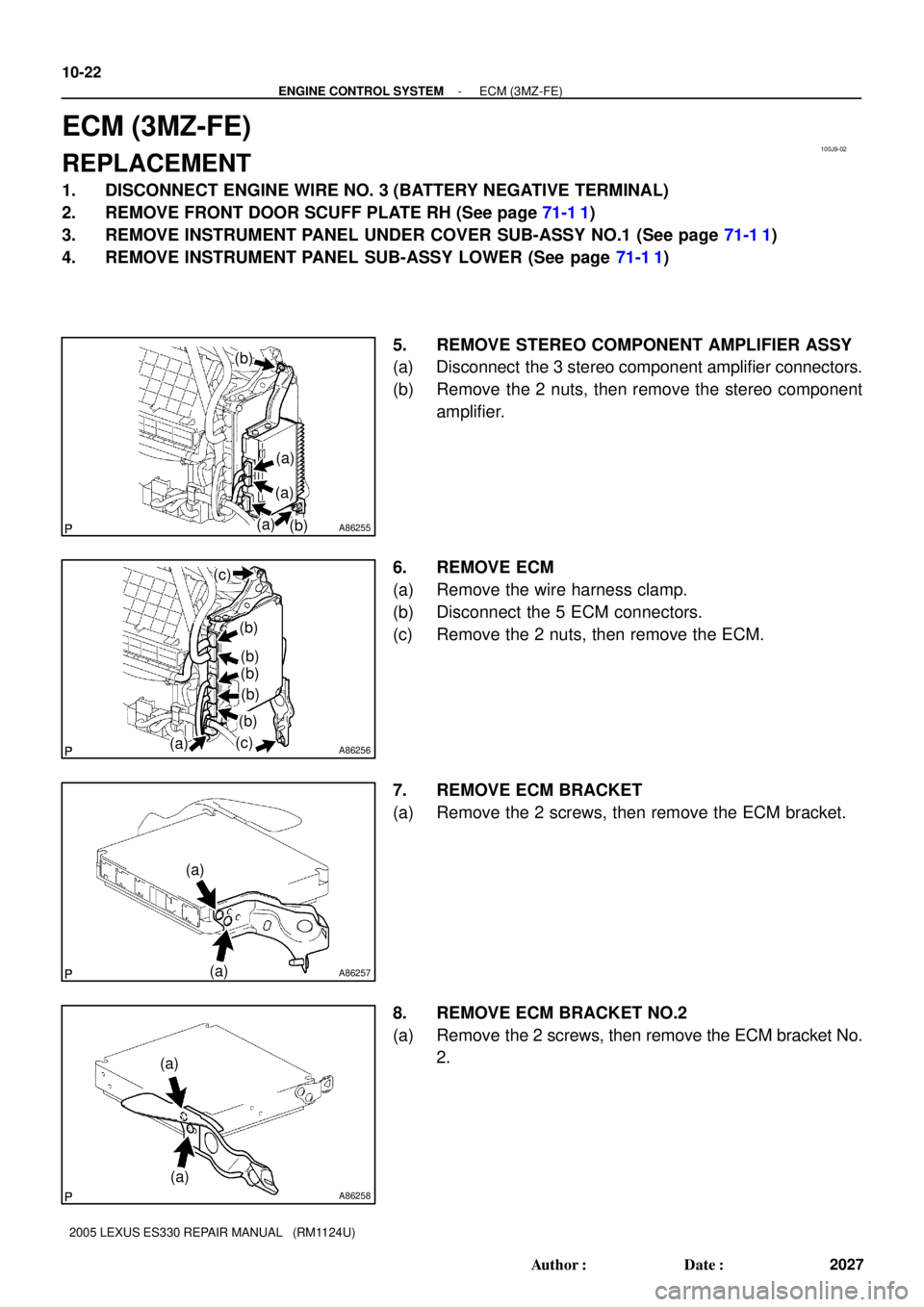
5. REMOVE STEREO COMPONENT AMPLIFIER ASSY
(a) Disconnect the 3 stereo component amplifier connectors.
(b) Remove the 2 nuts, then remove the stereo component
amplifier.
6. REMOVE ECM
(a) Remove the wire harness clamp.
(b) Disconnect the 5 ECM connectors.
(c) Remove the 2 nuts, then remove the ECM.
7. REMOVE ECM BRACKET
(a) Remove the 2 screws, then remove the ECM bracket.
8. REMOVE ECM BRACKET NO.2
(a) Remove the 2 screws, then remove the ECM bracket No.
2.
Page 580 of 969
A86259
(a)
(a)
- ENGINE CONTROL SYSTEMECM (3MZ-FE)
10-23
2028 Author�: Date�:
2005 LEXUS ES330 REPAIR MANUAL (RM1124U)
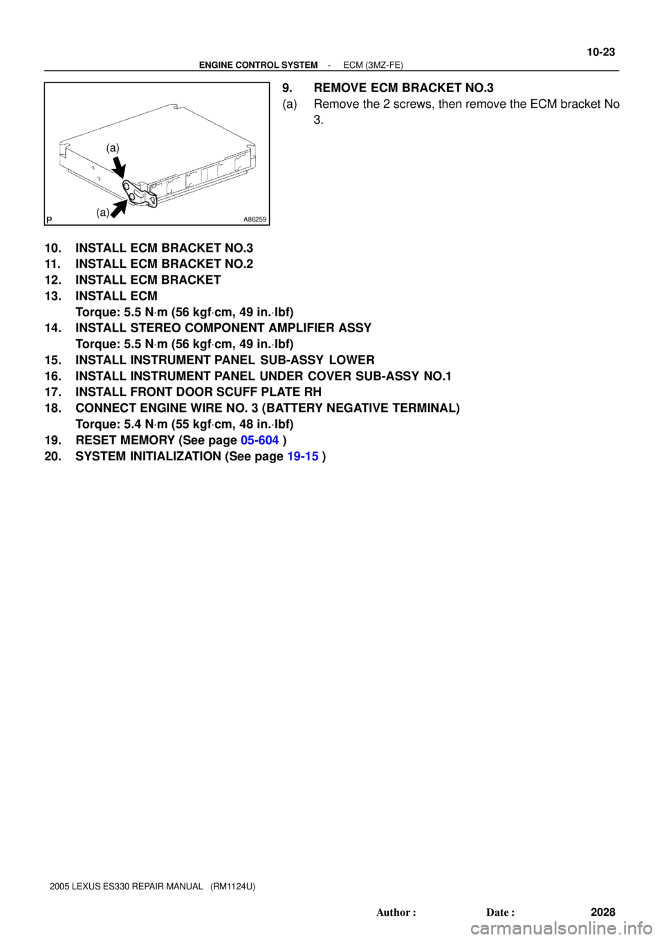
9. REMOVE ECM BRACKET NO.3
(a) Remove the 2 screws, then remove the ECM bracket No
3.
10. INSTALL ECM BRACKET NO.3
11. INSTALL ECM BRACKET NO.2
12. INSTALL ECM BRACKET
13. INSTALL ECM
Torque: 5.5 NVm (56 kgfVcm, 49 in.Vlbf)
14. INSTALL STEREO COMPONENT AMPLIFIER ASSY
Torque: 5.5 NVm (56 kgfVcm, 49 in.Vlbf)
15. INSTALL INSTRUMENT PANEL SUB-ASSY LOWER
16. INSTALL INSTRUMENT PANEL UNDER COVER SUB-ASSY NO.1
17. INSTALL FRONT DOOR SCUFF PLATE RH
18. CONNECT ENGINE WIRE NO. 3 (BATTERY NEGATIVE TERMINAL)
Torque: 5.4 NVm (55 kgfVcm, 48 in.Vlbf)
19. RESET MEMORY (See page 05-604)
20. SYSTEM INITIALIZATION (See page 19-15)
Page 581 of 969

11-1
2029 Author�: Date�:
2005 LEXUS ES330 REPAIR MANUAL (RM1124U)
FUEL SYSTEM (3MZ-FE)
PRECAUTION
1. PRECAUTION
(a) Before working o")
110XR-01
A62391
Circuit Opening Relay
- FUELFUEL SYSTEM (3MZ-FE)
11-1
2029 Author�: Date�:
2005 LEXUS ES330 REPAIR MANUAL (RM1124U)
FUEL SYSTEM (3MZ-FE)
PRECAUTION
1. PRECAUTION
(a) Before working on the fuel system, disconnect the engine wire No. 3 (battery negative terminal) from
battery.
(b) Do not smoke or work near open flame when working on the fuel system.
(c) Keep gasoline away from the rubber or leather parts.
2. DISCHARGE FUEL SYSTEM PRESSURE
CAUTION:
�Do not disconnect any parts of the fuel system pres-
sure until you have discharging the fuel system pres-
sure.
�Even after discharge the fuel pressure, place a shop
rag over fittings as you separate them in order to re-
duce risk of fuel spray on yourself or in the engine
compartment.
(a) Disconnect the engine wire No. 3 (battery negative termi-
nal).
(b) Remove the circuit opening relay from the engine room
relay block.
(c) Connect the engine wire No. 3 (battery negative terminal).
Torque: 5.4 NVm (55 kgfVcm, 48 in.Vlbf)
(d) Start the engine. After the engine has stopped on its own,
turn the ignition switch OFF.
HINT:
There is a case that DTC P0171 (system to lean) is output.
(e) Check that the engine does not start.
(f) Remove the fuel tank cap, then let the air out of the fuel
tank.
(g) Disconnect battery negative terminal.
(h) Reinstall the circuit opening relay.
3. FUEL SYSTEM
(a) When disconnecting the high fuel pressure line, a large
amount of gasoline will spill out. So observe these proce-
dures.
(1) Work in order to prevent gasoline from spilling out.
(2) Disconnect the fuel pump tube (see page 11-20).
(3) Drain the fuel remaining inside the fuel pump tube.