Page 636 of 969
120BZ-01
A86359
(a)
(b)
A86353
(c)
SST
A86353
SST
- EMISSION CONTROLAIR FUEL RATIO SENSOR (3MZ-FE (LH BANK))
12-23
2084 Author�: Date�:
2005 LEXUS ES330 REPAIR MANUAL (RM1124U)
AIR FUEL RATIO SENSOR (3MZ-FE (LH BANK))
REPLACEMENT
1. DISCONNECT ENGINE WIRE NO. 3 (BATTERY NEGATIVE TERMINAL)
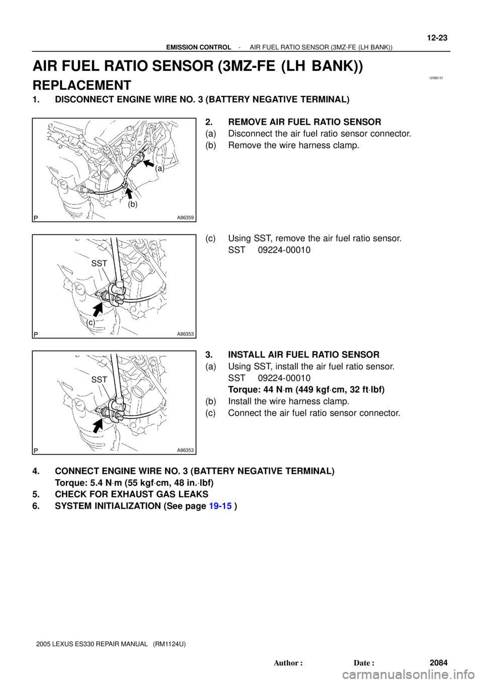
2. REMOVE AIR FUEL RATIO SENSOR
(a) Disconnect the air fuel ratio sensor connector.
(b) Remove the wire harness clamp.
(c) Using SST, remove the air fuel ratio sensor.
SST 09224-00010
3. INSTALL AIR FUEL RATIO SENSOR
(a) Using SST, install the air fuel ratio sensor.
SST 09224-00010
Torque: 44 NVm (449 kgfVcm, 32 ftVlbf)
(b) Install the wire harness clamp.
(c) Connect the air fuel ratio sensor connector.
4. CONNECT ENGINE WIRE NO. 3 (BATTERY NEGATIVE TERMINAL)
Torque: 5.4 NVm (55 kgfVcm, 48 in.Vlbf)
5. CHECK FOR EXHAUST GAS LEAKS
6. SYSTEM INITIALIZATION (See page 19-15)
Page 637 of 969
120BZ-01
A86359
(a)
(b)
A86353
(c)
SST
A86353
SST
- EMISSION CONTROLAIR FUEL RATIO SENSOR (3MZ-FE (LH BANK))
12-23
2084 Author�: Date�:
2005 LEXUS ES330 REPAIR MANUAL (RM1124U)
AIR FUEL RATIO SENSOR (3MZ-FE (LH BANK))
REPLACEMENT
1. DISCONNECT ENGINE WIRE NO. 3 (BATTERY NEGATIVE TERMINAL)
2. REMOVE AIR FUEL RATIO SENSOR
(a) Disconnect the air fuel ratio sensor connector.
(b) Remove the wire harness clamp.
(c) Using SST, remove the air fuel ratio sensor.
SST 09224-00010
3. INSTALL AIR FUEL RATIO SENSOR
(a) Using SST, install the air fuel ratio sensor.
SST 09224-00010
Torque: 44 NVm (449 kgfVcm, 32 ftVlbf)
(b) Install the wire harness clamp.
(c) Connect the air fuel ratio sensor connector.
4. CONNECT ENGINE WIRE NO. 3 (BATTERY NEGATIVE TERMINAL)
Torque: 5.4 NVm (55 kgfVcm, 48 in.Vlbf)
5. CHECK FOR EXHAUST GAS LEAKS
6. SYSTEM INITIALIZATION (See page 19-15)
Page 638 of 969
1307V-01
A82242
3-way
Connector Vacuum Gauge
A86347DLC3
Hand-held Tester
- INTAKEINTAKE AIR CONTROL SYSTEM (3MZ-FE)
13-1
2086 Author�: Date�:
2005 LEXUS ES330 REPAIR MANUAL (RM1124U)
INTAKE AIR CONTROL SYSTEM (3MZ-FE)
ON-VEHICLE INSPECTION
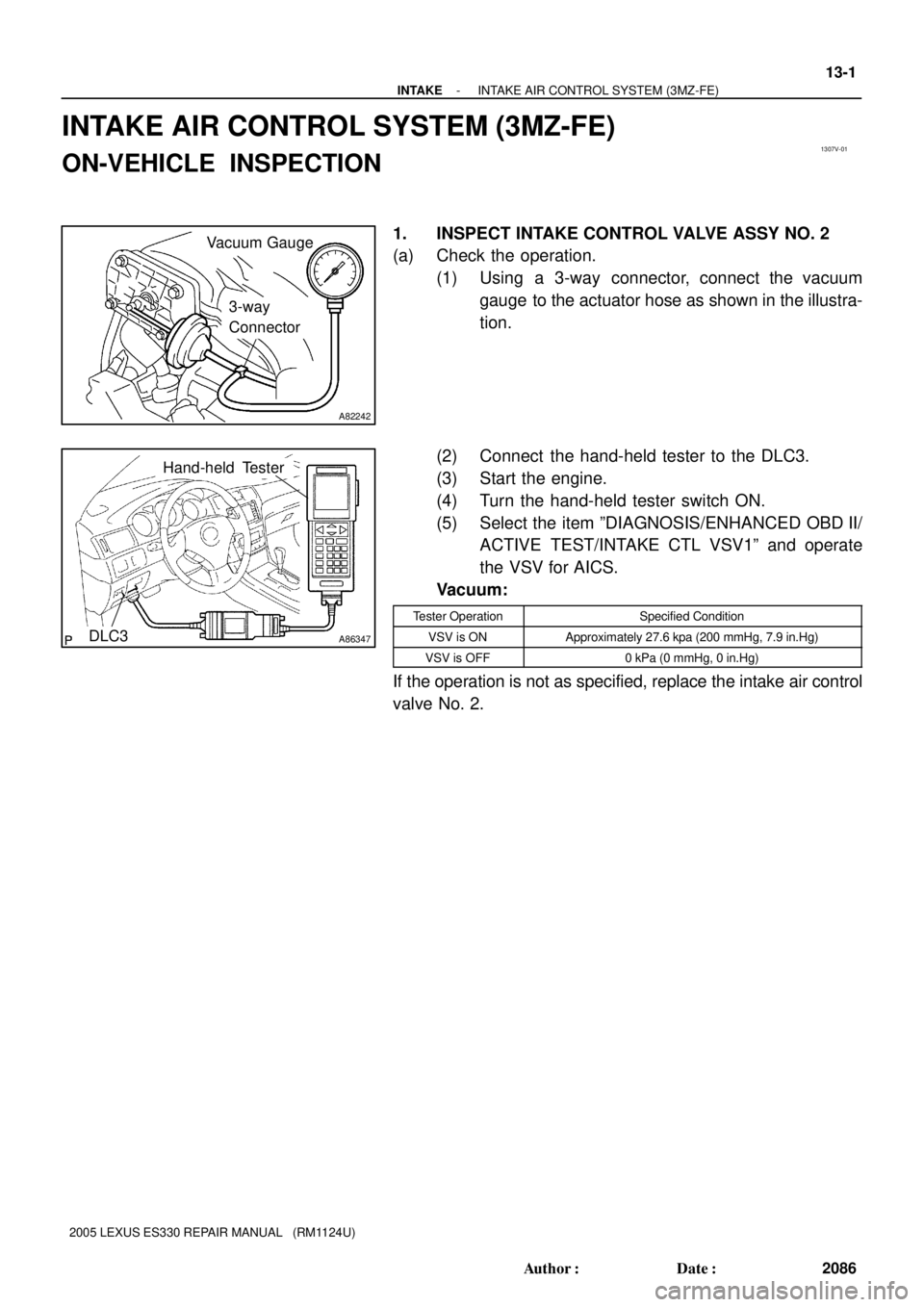
1. INSPECT INTAKE CONTROL VALVE ASSY NO. 2
(a) Check the operation.
(1) Using a 3-way connector, connect the vacuum
gauge to the actuator hose as shown in the illustra-
tion.
(2) Connect the hand-held tester to the DLC3.
(3) Start the engine.
(4) Turn the hand-held tester switch ON.
(5) Select the item ºDIAGNOSIS/ENHANCED OBD II/
ACTIVE TEST/INTAKE CTL VSV1º and operate
the VSV for AICS.
Vacuum:
Tester OperationSpecified Condition
VSV is ONApproximately 27.6 kpa (200 mmHg, 7.9 in.Hg)
VSV is OFF0 kPa (0 mmHg, 0 in.Hg)
If the operation is not as specified, replace the intake air control
valve No. 2.
Page 643 of 969

(b)(d)
(d)
(c)
(b)
(b)
(b)
A86221
(a)
(b)
(c)
(c) 13-6
- INTAKEINTAKE AIR CONTROL VALVE ASSY NO.3 (3MZ-FE)
2091 Author�: Date�:
2005 LEXUS ES330 REPAIR MANUAL (RM1124U)
INTAKE AI")
1307Y-01
A86220
(a)
(b)(d)
(d)
(c)
(b)
(b)
(b)
A86221
(a)
(b)
(c)
(c) 13-6
- INTAKEINTAKE AIR CONTROL VALVE ASSY NO.3 (3MZ-FE)
2091 Author�: Date�:
2005 LEXUS ES330 REPAIR MANUAL (RM1124U)
INTAKE AIR CONTROL VALVE ASSY NO.3 (3MZ-FE)
REPLACEMENT
1. DISCONNECT ENGINE WIRE NO. 3 (BATTERY NEGATIVE TERMINAL)
2. REMOVE RADIATOR LOWER AIR DEFLECTOR (See page 19-5)
3. REMOVE AIR CLEANER INLET ASSY (See page 19-5)
4. REMOVE AIR CLEANER CAP SUB-ASSY
(a) Disconnect the mass air flow meter connector.
(b) Disconnect the 4 vacuum hoses.
(c) Loosen the hose clamp bolt.
(d) Loosen the 2 bolts, then remove the air cleaner cap.
(e) Remove the air cleaner filter element.
5. REMOVE INTAKE AIR CONTROL VALVE ASSY NO.3
(a) Disconnect the VSV connector.
(b) Disconnect the vacuum hose.
(c) Unfasten the 2 claws, then remove the intake air control
valve No. 3.
6. INSTALL INTAKE AIR CONTROL VALVE ASSY NO.3
7. INSTALL AIR CLEANER CAP SUB-ASSY
Torque: 5.0 NVm (51 kgfVcm, 44 in.Vlbf)
8. INSTALL AIR CLEANER INLET ASSY (See page 19-5)
9. CHECK CONNECTION OF VACUUM HOSE (See page 14-29)
10. INSTALL RADIATOR LOWER AIR DEFLECTOR
11. CONNECT ENGINE WIRE NO. 3 (BATTERY NEGATIVE TERMINAL)
Torque: 5.4 NVm (55 kgfVcm, 48 in.Vlbf)
12. SYSTEM INITIALIZATION (See page 19-15)
Page 644 of 969
1307Z-01
A86218
(a)
(a)
A86219
(b)(c)
(d)
- INTAKEVACUUM SWITCHING VALVE ASSY NO.1 (3MZ-FE)
13-7
2092 Author�: Date�:
2005 LEXUS ES330 REPAIR MANUAL (RM1124U)
VACUUM SWITCHING VALVE ASSY NO.1 (3MZ-FE)
REPLACEMENT
1. DISCONNECT ENGINE WIRE NO. 3 (BATTERY NEGATIVE TERMINAL)
2. REMOVE V-BANK COVER SUB-ASSY (See page 10-1 1)
3. REMOVE EMISSION CONTROL VALVE SET (See page 12-19)
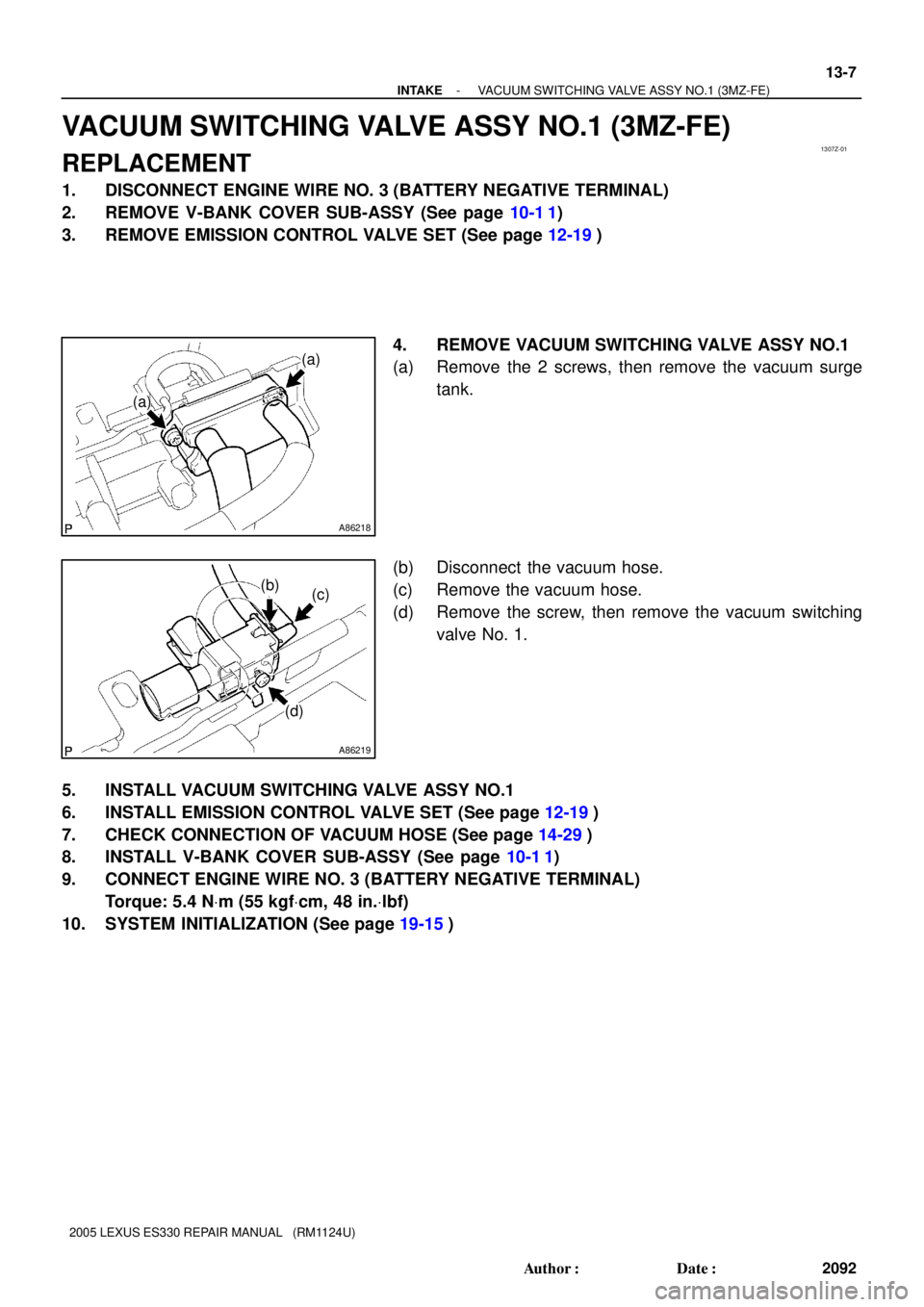
4. REMOVE VACUUM SWITCHING VALVE ASSY NO.1
(a) Remove the 2 screws, then remove the vacuum surge
tank.
(b) Disconnect the vacuum hose.
(c) Remove the vacuum hose.
(d) Remove the screw, then remove the vacuum switching
valve No. 1.
5. INSTALL VACUUM SWITCHING VALVE ASSY NO.1
6. INSTALL EMISSION CONTROL VALVE SET (See page 12-19)
7. CHECK CONNECTION OF VACUUM HOSE (See page 14-29)
8. INSTALL V-BANK COVER SUB-ASSY (See page 10-1 1)
9. CONNECT ENGINE WIRE NO. 3 (BATTERY NEGATIVE TERMINAL)
Torque: 5.4 NVm (55 kgfVcm, 48 in.Vlbf)
10. SYSTEM INITIALIZATION (See page 19-15)
Page 646 of 969
150B8-01
A86209
A86210
(a)
(b)
(a)
(b)
(b)
A86211
Plastic-faced Hammer
15-2
- EXHAUSTEXHAUST PIPE ASSY (3MZ-FE)
2275 Author�: Date�:
2005 LEXUS ES330 REPAIR MANUAL (RM1124U)
Removal & Installation and Disassembly & Reassembly
1. DISCONNECT ENGINE WIRE NO. 3 (BATTERY NEGATIVE TERMINAL)
2. REMOVE HEATED OXYGEN SENSOR (See page 12-24)
SST 09224-00010
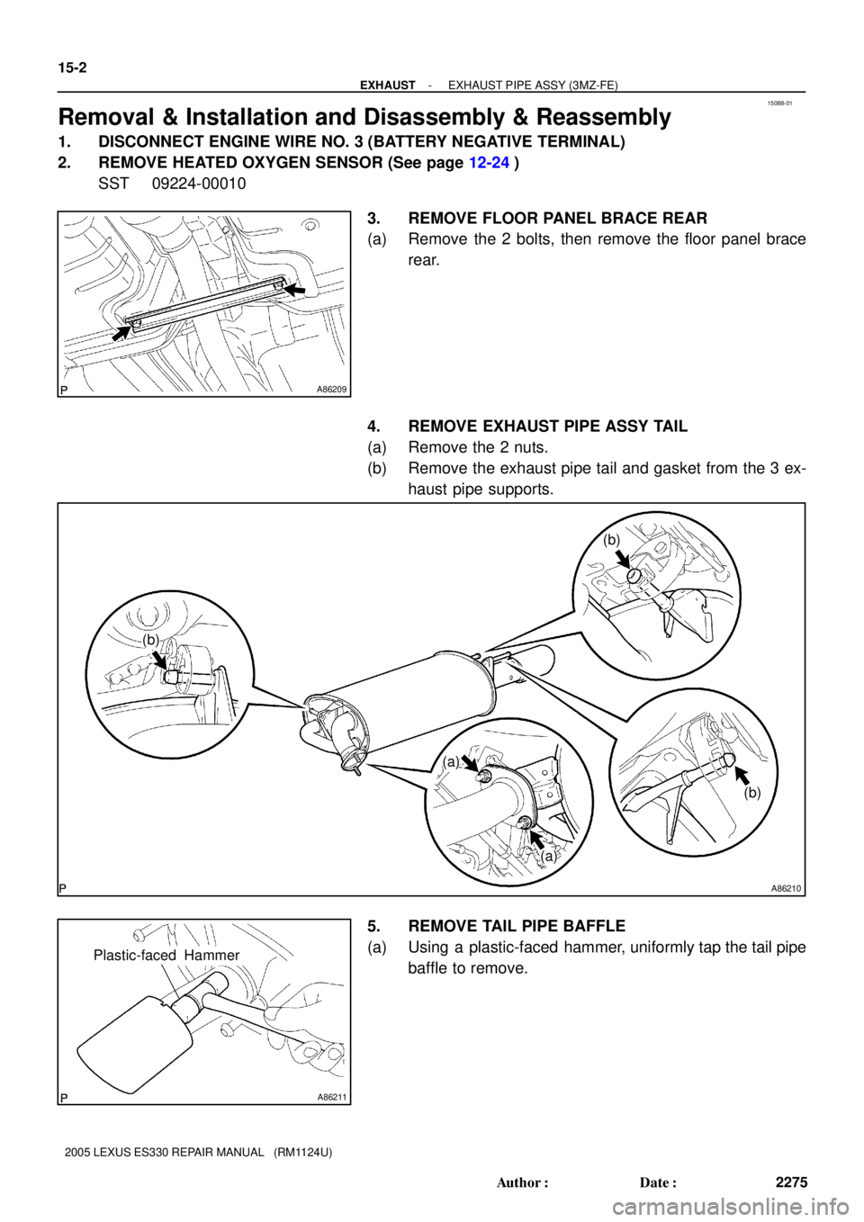
3. REMOVE FLOOR PANEL BRACE REAR
(a) Remove the 2 bolts, then remove the floor panel brace
rear.
4. REMOVE EXHAUST PIPE ASSY TAIL
(a) Remove the 2 nuts.
(b) Remove the exhaust pipe tail and gasket from the 3 ex-
haust pipe supports.
5. REMOVE TAIL PIPE BAFFLE
(a) Using a plastic-faced hammer, uniformly tap the tail pipe
baffle to remove.
Page 649 of 969
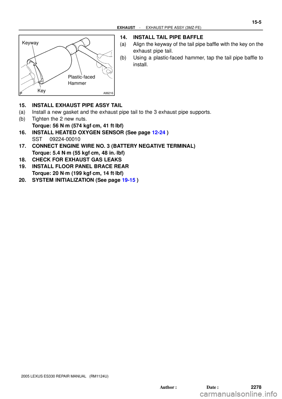
A86216
Keyway
KeyPlastic-faced
Hammer
- EXHAUSTEXHAUST PIPE ASSY (3MZ-FE)
15-5
2278 Author�: Date�:
2005 LEXUS ES330 REPAIR MANUAL (RM1124U)
14. INSTALL TAIL PIPE BAFFLE
(a) Align the keyway of the tail pipe baffle with the key on the
exhaust pipe tail.
(b) Using a plastic-faced hammer, tap the tail pipe baffle to
install.
15. INSTALL EXHAUST PIPE ASSY TAIL
(a) Install a new gasket and the exhaust pipe tail to the 3 exhaust pipe supports.
(b) Tighten the 2 new nuts.
Torque: 56 NVm (574 kgfVcm, 41 ftVlbf)
16. INSTALL HEATED OXYGEN SENSOR (See page 12-24)
SST 09224-00010
17. CONNECT ENGINE WIRE NO. 3 (BATTERY NEGATIVE TERMINAL)
Torque: 5.4 NVm (55 kgfVcm, 48 in.Vlbf)
18. CHECK FOR EXHAUST GAS LEAKS
19. INSTALL FLOOR PANEL BRACE REAR
Torque: 20 NVm (199 kgfVcm, 14 ftVlbf)
20. SYSTEM INITIALIZATION (See page 19-15)
Page 650 of 969

16-1
2279 Author�: Date�:
2005 LEXUS ES330 REPAIR MANUAL (RM1124U)
COOLING SYSTEM (3MZ-FE)
ON-VEHICLE INSPECTION
1. INSPECT COO")
160QB-01
A60522
Radiator Cap
Tester
- COOLINGCOOLING SYSTEM (3MZ-FE)
16-1
2279 Author�: Date�:
2005 LEXUS ES330 REPAIR MANUAL (RM1124U)
COOLING SYSTEM (3MZ-FE)
ON-VEHICLE INSPECTION
1. INSPECT COOLING SYSTEM FOR LEAKS
(a) Remove the water outlet cap.
CAUTION:
To avoid the danger of being burned, do not remove the wa-
ter outlet cap while the engine and radiator are still hot.
Thermal expansion will cause hot engine coolant and
steam to blow out from the radiator.
(b) Fill the radiator with coolant, then attach a radiator cap
tester.
(c) Warm up the engine.
(d) Pump it to 118 kPa (1.2 kgf/cm
2, 17.1 psi), then check that
the pressure does not drop.
If the pressure drops, check the hoses, radiator and water
pump for leaks. If there are no signs or traces of external coolant
leaks, check the heater core, cylinder block and head.
(e) Reinstall the water outlet cap.
2. CHECK ENGINE COOLANT LEVEL AT RESERVOIR
(a) The engine coolant should be between the ºLOWº and ºFULLº lines when the engine is cold.
If low, check for leaks and add ºToyota Super Long Life Coolantº or similar high quality ethylene glycol based
non-silicate, non-amine, non-nitrite, and non-borate coolant with long-life hybrid organic acid technology
up to the ºFULLº line.
3. CHECK ENGINE COOLANT QUALITY
(a) Remove the water outlet cap.
CAUTION:
To avoid the danger of being burned, do not remove the water outlet cap while the engine and radiator
are still hot. Thermal expansion will cause hot engine coolant and steam to blow out from the radiator.
(b) Check if there are any excessive deposits of rust or scale around the water outlet cap and water outlet
filler hole; the coolant should free of oil.
If excessively dirty, replace the coolant.
(c) Reinstall the water outlet cap.