Page 681 of 969
A78396
8.5 (87, 75 in.Vlbf)
125 (1,275, 92)
43 (438, 32)
Timing Belt Idler
Sub-assy No. 2Camshaft Timing
Pulley x6Timing Belt No. 3 Cover
CollarGasket
Bushing
Engine Wire
34 (347, 25)
Timing Belt Idler Sub-assy No. 1
N´m (kgf´cm, ft´lbf)
: Specified torque
8.0 (82, 71 in.Vlbf)
Crankshaft Timing Pulley
Timing Belt Plate
- LUBRICATIONOIL PUMP ASSY (3MZ-FE)
17-5
2310 Author�: Date�:
2005 LEXUS ES330 REPAIR MANUAL (RM1124U)
Page 682 of 969
A84922
N´m (kgf´cm, ft´lbf)
: Specified torqueEngine Mounting Bracket RH
54 (551, 40)
8.4 (85, 74 in.Vlbf)
87 (887, 64)
43 (438, 32)
18 (184, 13)
25 (250, 18)
25 (250, 18)
52 (530, 38)
87 (887, 64)
Engine Mounting Insulator RH
Generator Belt
Adjusting Bar
Compressor Mounting
Bracket No. 1
Fan Belt Adjusting
Bar Bracket Compressor and Magnetic Clutch
Engine Mounting
Insulator FR
43 (439, 32)95 (969, 70)
25 (250, 18)
25 (250, 18)
26 (260, 19)
54 (551, 40)
54 (551, 40)
62 (633, 46)
Exhaust Pipe Assy Front
Exhaust Pipe No. 1 Support Bracket Front
� Exhaust Pipe
Gasket
� Non-reusable part33 (337, 24)
�
56 (571, 41)
33 (337, 24)
Exhaust Pipe No. 1
Support Bracket Rear
�
21 (214, 15)
Exhaust Pipe Support
Bracket No. 1
� O-ring
8.0 (82, 71 in.Vlbf)
Oil Level Gage Guide
Oil Level Gage
Sub-assy
62 (633, 46)
� Exhaust Pipe
Gasket
� Exhaust Pipe
Gasket 17-6
- LUBRICATIONOIL PUMP ASSY (3MZ-FE)
2311 Author�: Date�:
2005 LEXUS ES330 REPAIR MANUAL (RM1124U)
Page 685 of 969

17-9
2314 Author�: Date�:
REPLACEMENT
1. DISCONNECT BATTERY NEGATIVE TERMINAL
2. DRAIN ENGINE OIL (See page 17-20)
3. REMOVE FRONT WHEEL RH
4. REMOV")
170HN-02
A52889
- LUBRICATIONOIL PUMP ASSY (3MZ-FE)
17-9
2314 Author�: Date�:
REPLACEMENT
1. DISCONNECT BATTERY NEGATIVE TERMINAL
2. DRAIN ENGINE OIL (See page 17-20)
3. REMOVE FRONT WHEEL RH
4. REMOVE ENGINE UNDER COVER NO.1
5. REMOVE ENGINE UNDER COVER NO.2
6. REMOVE FRONT FENDER APRON SEAL RH
7. REMOVE V (COOLER COMPRESSOR TO CRANKSHAFT PULLEY) BELT NO.1
(See page 14-5)
8. REMOVE GENERATOR ASSY (See page 19-21)
9. REMOVE VANE PUMP V BELT (See page 14-5)
10. REMOVE ENGINE MOVING CONTROL ROD (See page 14-79)
11. REMOVE ENGINE MOUNTING STAY NO.2 RH (See page 14-79)
12. REMOVE GENERATOR BRACKET NO.2 (See page 14-79)
13. REMOVE CRANKSHAFT PULLEY (See page 14-79)
SST 09213-54015 (91651-60855), 09330-00021, 09950-50013 (09951-05010, 09952-05010,
09953-05020, 09954-05031)
14. REMOVE TIMING BELT NO.1 COVER
15. REMOVE TIMING BELT NO.2 COVER (See page 14-79)
16. REMOVE ENGINE MOUNTING BRACKET RH (See page 14-79)
17. REMOVE TIMING BELT GUIDE NO.2
18. REMOVE TIMING BELT (See page 14-79)
19. REMOVE TIMING BELT IDLER SUB-ASSY NO.2
20. REMOVE CAMSHAFT TIMING PULLEY (See page 14-93)
SST 09960-10010 (09962-01000, 09963-01000), 09249-63010
21. REMOVE TIMING BELT NO.3 COVER (See page 14-93)
22. REMOVE TIMING BELT IDLER SUB-ASSY NO.1 (See page 16-13)
23. REMOVE CRANKSHAFT TIMING PULLEY (See page 14-138)
SST 09950-50013 (09951-05010, 09952-05010, 09953-05020, 09954-05011)
24. REMOVE EXHAUST PIPE NO.1 SUPPORT BRACKET FRONT (See page 15-2)
25. REMOVE EXHAUST PIPE NO.1 SUPPORT BRACKET REAR (See page 15-2)
26. REMOVE EXHAUST PIPE ASSY FRONT (See page 15-2)
27. REMOVE EXHAUST PIPE SUPPORT BRACKET NO.1 (See page 40-9)
28. REMOVE OIL LEVEL GAGE GUIDE (See page 14-133)
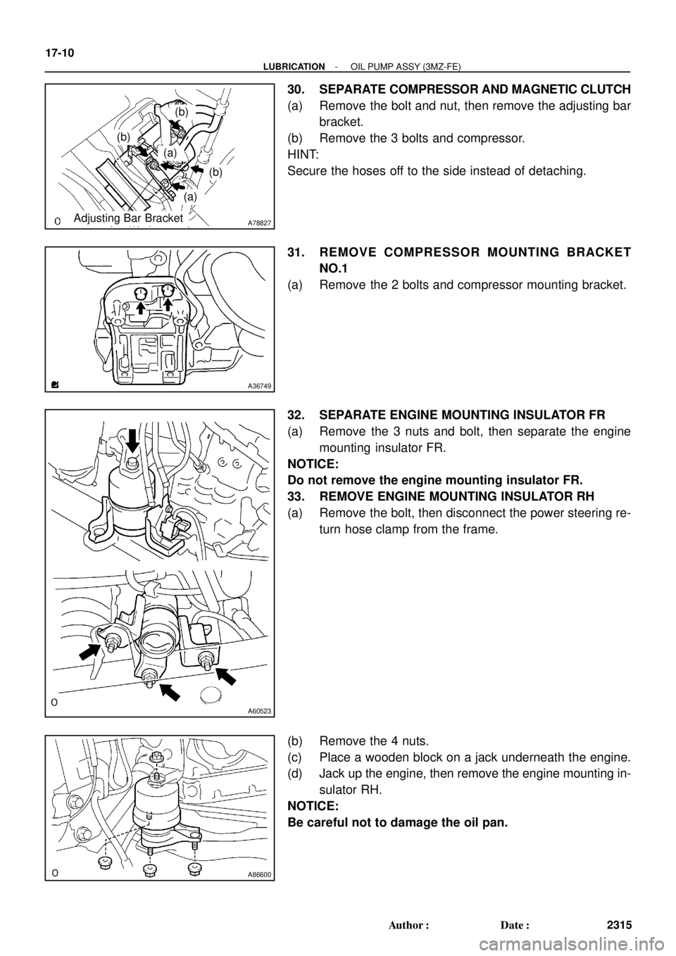
29. REMOVE GENERATOR BELT ADJUSTING BAR
(a) Remove the 2 bolts and 2 nuts, then remove the adjusting
bar.
Page 686 of 969
A78827Adjusting Bar Bracket
(b)
(a)
(a)
(b)
(b)
A36749
A60523
A86600
17-10
- LUBRICATIONOIL PUMP ASSY (3MZ-FE)
2315 Author�: Date�:
30. SEPARATE COMPRESSOR AND MAGNETIC CLUTCH
(a) Remove the bolt and nut, then remove the adjusting bar
bracket.
(b) Remove the 3 bolts and compressor.
HINT:
Secure the hoses off to the side instead of detaching.
31. REMOVE COMPRESSOR MOUNTING BRACKET
NO.1
(a) Remove the 2 bolts and compressor mounting bracket.
32. SEPARATE ENGINE MOUNTING INSULATOR FR
(a) Remove the 3 nuts and bolt, then separate the engine
mounting insulator FR.
NOTICE:
Do not remove the engine mounting insulator FR.
33. REMOVE ENGINE MOUNTING INSULATOR RH
(a) Remove the bolt, then disconnect the power steering re-
turn hose clamp from the frame.
(b) Remove the 4 nuts.
(c) Place a wooden block on a jack underneath the engine.
(d) Jack up the engine, then remove the engine mounting in-
sulator RH.
NOTICE:
Be careful not to damage the oil pan.
Page 687 of 969
A52015
A36750
A00019
SST
SST
A78379
- LUBRICATIONOIL PUMP ASSY (3MZ-FE)
17-1 1
2316 Author�: Date�:
34. REMOVE ENGINE MOUNTING BRACKET RH
(a) Remove the 4 bolts and nut, then remove the bracket.
35. REMOVE OIL PAN SUB-ASSY NO.2
(a) Remove the 10 bolts and 2 nuts.
(b) Insert the blade of SST between the oil pan No. 1 and oil
pan No. 2, then cut off the sealer and remove the oil pan
No. 2.
SST 09032-00100
NOTICE:
�Be careful not to damage the contact surface of the oil
pan No. 1 where the oil pan No. 2 is mounted.
�Do not damage the flange portion of the oil pan No. 2
when removing.
36. REMOVE OIL STRAINER SUB-ASSY
(a) Remove the bolt and 2 nuts, then remove the oil strainer and gasket.
37. REMOVE OIL PAN SUB-ASSY
(a) Remove the 2 bolts and nut, then disconnect the engine
oil level sensor connector.
(b) Remove the 2 bolts and flywheel housing under cover.
Page 689 of 969
A36784
A78725
Seal Packing
Seal Width
2 to 3 mm
(0.08 to 0.12 in.) A
A
BB
C
C
A36785
- LUBRICATIONOIL PUMP ASSY (3MZ-FE)
17-13
2318 Author�: Date�:
41. INSTALL OIL PUMP ASSY
(a) Remove any old seal packing material from the contact
surface.
(b) Apply a light coat of engine oil to a new O-ring, then place
it on the cylinder block.
(c) Apply a continuous bead of seal packing (Diameter 2 to
3 mm (0.08 to 0.12 in.)) as shown in the illustration.
Seal packing: Part No. 08826-00080 or equivalent
NOTICE:
�Remove any oil from contact surface.
�Apply seal packing to the inner side of the bolt holes.
�Install the oil pump within 3 minutes after applying
seal packing.
�Do not expose the seal packing to engine oil within 2
hours after installing.
(d) Align the key of the oil pump drive gear with the keyway
located on the crankshaft, then slide the oil pump into
place.
Page 690 of 969
 AAB
B Region ºXº Region ºYº 17-14
- LUBRICATIONOIL PUMP ASSY (3MZ-FE)
2319 Author�: Date�:
(e) Install the oi")
A51990
A
B
C
B
A
A
A
A
A
A78726
Seal Packing
Seal Width
3 to 4 mm
(0.12 to 0.16 in.) AAB
B Region ºXº Region ºYº 17-14
- LUBRICATIONOIL PUMP ASSY (3MZ-FE)
2319 Author�: Date�:
(e) Install the oil pump with the 9 bolts. Tighten the bolts uni-
formly in several steps.
Torque:
8.0 NVm (82 kgfVcm, 71 in.Vlbf) for bolt A
20 NVm (199 kgfVcm, 14 ftVlbf) for bolt B
43 NVm (439 kgfVcm, 32 ftVlbf) for bolt C
42. INSTALL CRANKSHAFT POSITION SENSOR
Torque: 8.0 NVm (80 kgfVcm, 71 in.Vlbf)
43. INSTALL OIL PAN SUB-ASSY
(a) Remove any old seal packing from the contact surface.
(b) Apply a continuous bead of seal packing (Diameter 3 to
4 mm (0.12 to 0.16 in.)) as shown in the illustration.
Seal packing: Part No. 08826-00080 or equivalent
NOTICE:
�Remove any oil from the contact surface.
�Apply seal packing to the outer side of the bolt holes
in the region ºXº.
�Apply seal packing to the inner side of the bolt holes
in the region ºYº.
�Install the oil pan within 3 minutes after applying seal
packing.
�Do not expose the seal packing to engine oil within 2
hours after installing.
(c) Install the oil pan with the 17 bolts and 2 nuts. Tighten the
bolts uniformly in several steps.
Torque:
8.0 NVm (82 kgfVcm, 71 in.Vlbf) for 10 mm head
20 NVm (199 kgfVcm, 14 ftVlbf) for 12 mm head
37 NVm (379 kgfVcm, 27 ftVlbf) for 14 mm head
(d) Install the flywheel housing under cover with the 2 bolts.
Torque: 7.8 NVm (80 kgfVcm, 69 in.Vlbf)
(e) Install the engine oil level sensor connector with the 2
bolts and nut.
Torque: 8.4 NVm (85 kgfVcm, 74 in.Vlbf)
44. INSTALL OIL STRAINER SUB-ASSY
(a) Install a new gasket and the oil strainer with the bolt and 2 nuts.
Torque: 8.0 NVm (82 kgfVcm, 71 in.Vlbf)
Page 691 of 969
 AA
BB
A78825
B C
A
A
A
A86600
A
B
BB
- LUBRICATIONOIL PUMP ASSY (3MZ-FE)
17-15
2320 Author�: Date�:
45. INSTALL OIL PAN SUB-ASSY NO.2
(a")
A78727
Seal Packing
Seal Width
4 to 5 mm
(0.16 to 0.20 in.) AA
BB
A78825
B C
A
A
A
A86600
A
B
BB
- LUBRICATIONOIL PUMP ASSY (3MZ-FE)
17-15
2320 Author�: Date�:
45. INSTALL OIL PAN SUB-ASSY NO.2
(a) Remove any old seal packing from the contact surface.
(b) Apply a continuous bead of seal packing (Diameter 4 to
5 mm (0.16 to 0.20 in.)) as shown in the illustration.
Seal packing: Part No. 08826-00080 or equivalent
NOTICE:
�Remove any oil from the contact surface.
�Apply seal packing to the inner side of the bolt holes.
�Install the oil pan within 3 minutes after applying seal
packing.
�Do not expose the seal packing to engine oil within 2
hours after installing.
(c) Install the oil pan No. 2 with the 10 bolts and 2 nuts.
Torque: 8.0 NVm (82 kgfVcm, 71 in.Vlbf)
46. INSTALL ENGINE MOUNTING BRACKET RH
Torque:
54 NVm (551 kgfVcm,
40 ftVlbf) for bolt A
54 NVm (551 kgfVcm,
40 ftVlbf) for nut B
43 NVm (439 kgfVcm,
32 ftVlbf) for bolt C
47. INSTALL ENGINE MOUNTING INSULATOR RH
Torque:
95 NVm (969 kgfVcm,
70 ftVlbf) for nut A
87 NVm (887 kgfVcm,
64 ftVlbf) for nut B

125 (1,275, 92)
43 (438, 32)
Timing Belt Idler
Sub-assy No. 2Camshaft Timing
Pulley x6Timing Belt No. 3 Cover
CollarGasket
Bushing
Engine Wire
34 (347, 25)
Timing Belt Id")

: Specified torqueEngine Mounting Bracket RH
54 (551, 40)
8.4 (85, 74 in.Vlbf)
87 (887, 64)
43 (438, 32)
18 (184, 13)
25 (250, 18)
25 (250, 18)
52 (530, 38)
87 (887, 64)")