Page 566 of 969
100J4-01
A86358N´m (kgf´cm, ft´lbf) : Specified torque
7.9 (81, 70 in.Vlbf)x3
V-bank Cover Sub-assy
Mass Air Flow
Meter Connector Fuel Vapor Feed Hose
Assy
Vacuum Hose
Air Cleaner Cap
Sub-assy
Air Cleaner Filter
Element Sub-assy
5.0 (51, 44 in.Vlbf)
W/O TEMS:
Front Suspension Upper Brace Center
80 (816, 59)
Spacer
x2
Vacuum Hose
80 (816, 59)x2
Spacer
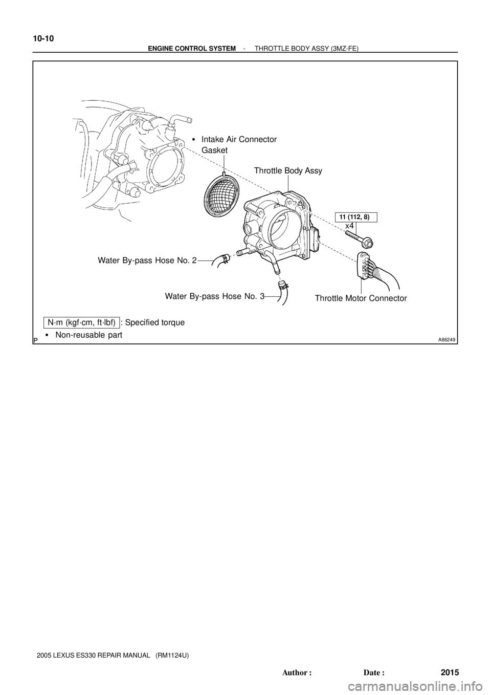
- ENGINE CONTROL SYSTEMTHROTTLE BODY ASSY (3MZ-FE)
10-9
2014 Author�: Date�:
2005 LEXUS ES330 REPAIR MANUAL (RM1124U)
THROTTLE BODY ASSY (3MZ-FE)
COMPONENTS
Page 567 of 969
A86249� Non-reusable part
N´m (kgf´cm, ft´lbf) : Specified torque� Intake Air Connector
Gasket
Throttle Body Assy
Water By-pass Hose No. 2
Water By-pass Hose No. 3
Throttle Motor Connector
11 (112, 8)
x4 10-10
- ENGINE CONTROL SYSTEMTHROTTLE BODY ASSY (3MZ-FE)
2015 Author�: Date�:
2005 LEXUS ES330 REPAIR MANUAL (RM1124U)
Page 568 of 969
(a)
(a)
(b) 2 Retainers
Socket Hexagon
Wrench 5
A86252
(a)
(b)
(d)
(e)
(b)
(b)
(b)
(c)
(d)
(e)
(f)
A86253
(a)
(c) (b)
- ENGINE CONTROL SYSTEMTHROTTLE BODY ASSY (3MZ-FE)
10-1")
100J5-01
A86250
A86251
(a)(a)
(a)
(b) 2 Retainers
Socket Hexagon
Wrench 5
A86252
(a)
(b)
(d)
(e)
(b)
(b)
(b)
(c)
(d)
(e)
(f)
A86253
(a)
(c) (b)
- ENGINE CONTROL SYSTEMTHROTTLE BODY ASSY (3MZ-FE)
10-1 1
2016 Author�: Date�:
2005 LEXUS ES330 REPAIR MANUAL (RM1124U)
REPLACEMENT
1. DISCONNECT ENGINE WIRE NO. 3 (BATTERY NEGATIVE TERMINAL)
2. REMOVE RADIATOR LOWER AIR DEFLECTOR (See page 19-5)
3. DRAIN ENGINE COOLANT (See page 19-5)
4. REMOVE FRONT SUSPENSION UPPER BRACE
CENTER (W/O TEMS)
(a) Remove the 4 nuts, then remove the front suspension up-
per brace center and 4 spacers.
(b) Temporarily tighten the 4 nuts.
5. REMOVE V-BANK COVER SUB-ASSY
(a) Using a socket hexagon wrench 5, remove the 3 nuts.
(b) Unfasten the 2 retainers, then remove the V-bank cover.
6. REMOVE AIR CLEANER CAP SUB-ASSY
(a) Disconnect the mass air flow meter connector.
(b) Disconnect the 4 vacuum hoses.
(c) Disconnect the ventilation hose No. 2.
(d) Disconnect the fuel vapor feed hose from the 2 hose
clamps.
(e) Loosen the 2 air cleaner cap bolts.
(f) Loosen the air cleaner hose clamp bolt, then remove the
air cleaner cap.
(g) Remove the air cleaner filter element.
7. REMOVE THROTTLE BODY ASSY
(a) Disconnect the throttle motor connector.
(b) Disconnect the water by-pass hose No. 2.
(c) Disconnect the water by-pass hose No. 3.
Page 569 of 969

(d)
(d)
(d) 10-12
- ENGINE CONTROL SYSTEMTHROTTLE BODY ASSY (3MZ-FE)
2017 Author�: Date�:
2005 LEXUS ES330 REPAIR MANUAL (RM1124U)
(d) Remove the 4 bolts, then remove the throttle body.
(")
A86254
(d)
(d)
(d)
(d) 10-12
- ENGINE CONTROL SYSTEMTHROTTLE BODY ASSY (3MZ-FE)
2017 Author�: Date�:
2005 LEXUS ES330 REPAIR MANUAL (RM1124U)
(d) Remove the 4 bolts, then remove the throttle body.
(e) Remove the gasket from the intake air connector.
8. INSTALL THROTTLE BODY ASSY
(a) Install a new gasket to the intake air connector.
(b) Install the throttle body with the 4 bolts.
Torque: 11 NVm (112 kgfVcm, 8 ftVlbf)
(c) Connect the water by-pass hose No. 3.
(d) Connect the water by-pass hose No. 2.
(e) Connect the throttle motor connector.
9. INSTALL AIR CLEANER CAP SUB-ASSY
Torque: 5.0 NVm (51 kgfVcm, 44 in.Vlbf)
10. CHECK CONNECTION OF VACUUM HOSE (See page 14-29)
11. CONNECT ENGINE WIRE NO. 3 (BATTERY NEGATIVE TERMINAL)
Torque: 5.4 NVm (55 kgfVcm, 48 in.Vlbf)
12. ADD ENGINE COOLANT (See page 16-9)
13. CHECK FOR ENGINE COOLANT LEAKS (See page 16-1)
14. INSTALL V-BANK COVER SUB-ASSY
(a) Fit the 2 retainers, then install the V-bank cover.
(b) Using a socket hexagon wrench 5, tighten the 3 nuts.
Torque: 7.9 NVm (81 kgfVcm, 70 in.Vlbf)
15. INSTALL FRONT SUSPENSION UPPER BRACE CENTER (W/O TEMS)
Torque: 80 NVm (816 kgfVcm, 59 ftVlbf)
16. INSTALL RADIATOR LOWER AIR DEFLECTOR
17. SYSTEM INITIALIZATION (See page 19-15)
Page 570 of 969
100J6-02
A86358N´m (kgf´cm, ft´lbf) : Specified torque
7.9 (81, 70 in.Vlbf)x3
V-bank Cover Sub-assy
Mass Air Flow
Meter Connector Fuel Vapor Feed Hose
Assy
Vacuum Hose
Air Cleaner Cap
Sub-assy
Air Cleaner Filter
Element Sub-assy
5.0 (51, 44 in.Vlbf)
W/O TEMS:
Front Suspension Upper Brace Center
80 (816, 59)
Spacer
x2
Vacuum Hose
80 (816, 59)x2
Spacer
- ENGINE CONTROL SYSTEMKNOCK SENSOR (3MZ-FE)
10-13
2018 Author�: Date�:
2005 LEXUS ES330 REPAIR MANUAL (RM1124U)
KNOCK SENSOR (3MZ-FE)
COMPONENTS
Page 571 of 969
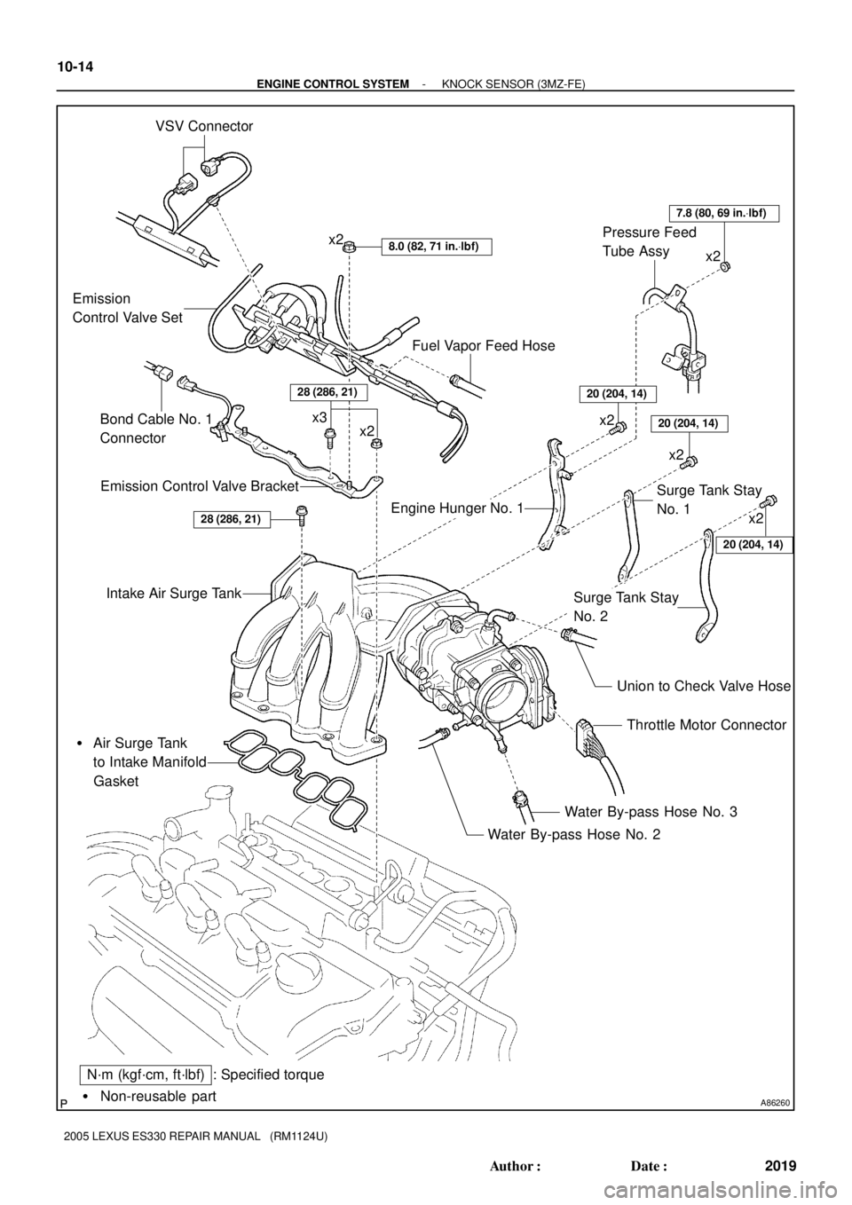
A86260� Non-reusable part
: Specified torque VSV Connector
8.0 (82, 71 in.Vlbf)x2
Emission
Control Valve Set
Emission Control Valve Bracket
Intake Air Surge Tank
� Air Surge Tank
to Intake Manifold
Gasket
Throttle Motor Connector
Water By-pass Hose No. 3
Water By-pass Hose No. 2
N´m (kgf´cm, ft´lbf)
Union to Check Valve Hose
Fuel Vapor Feed Hose
x2 x3
Engine Hunger No. 1Surge Tank Stay
No. 1
Surge Tank Stay
No. 2
20 (204, 14)
20 (204, 14)
20 (204, 14)
7.8 (80, 69 in.Vlbf)
x2
x2 Pressure Feed
Tube Assy
28 (286, 21)
x2
x2
Bond Cable No. 1
Connector
28 (286, 21)
10-14
- ENGINE CONTROL SYSTEMKNOCK SENSOR (3MZ-FE)
2019 Author�: Date�:
2005 LEXUS ES330 REPAIR MANUAL (RM1124U)
Page 572 of 969
A86261� Non-reusable part
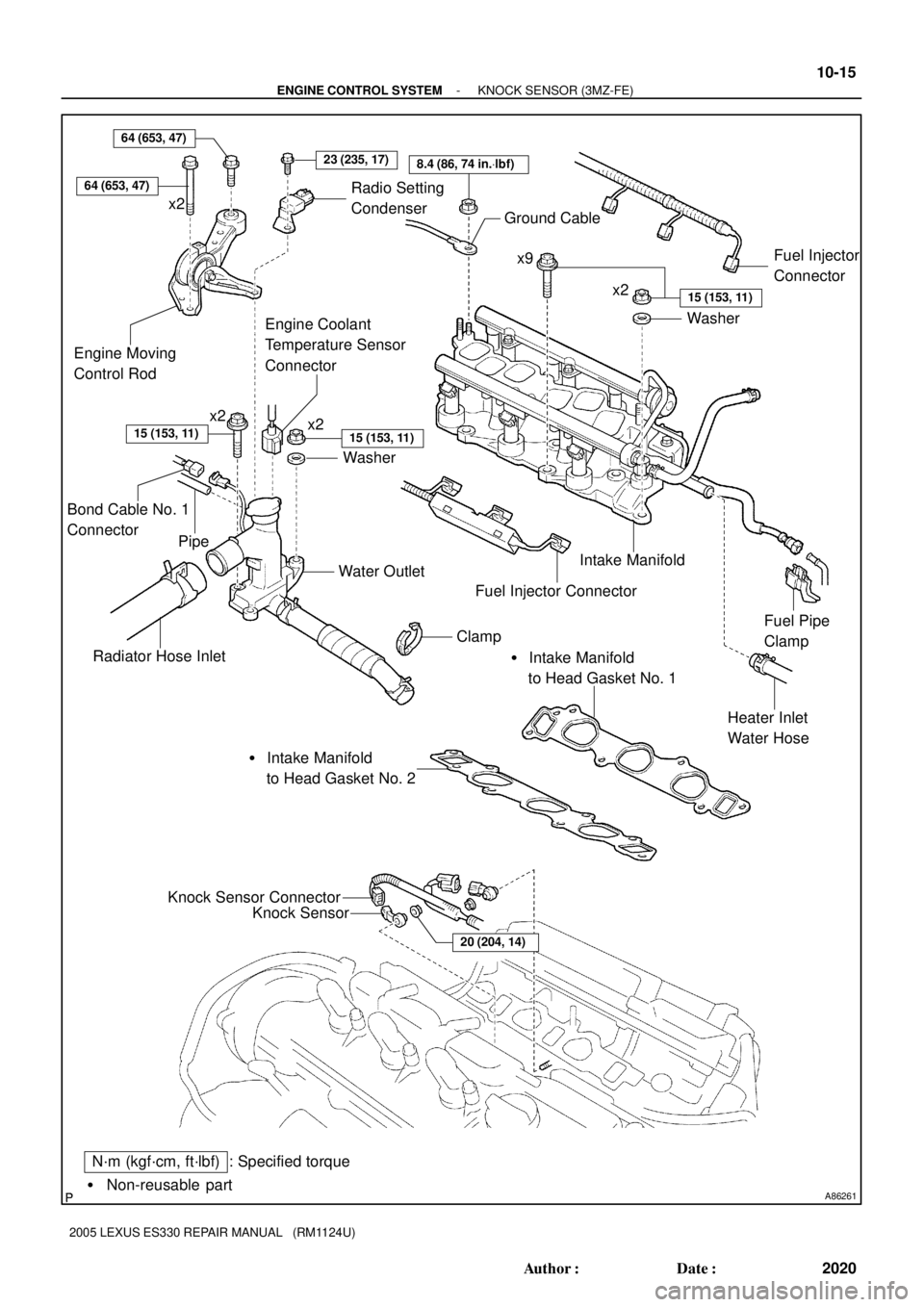
: Specified torqueN´m (kgf´cm, ft´lbf)Knock Sensor
Knock Sensor Connector
20 (204, 14)
� Intake Manifold
to Head Gasket No. 2� Intake Manifold
to Head Gasket No. 1
Radiator Hose InletWater Outlet
Heater Inlet
Water Hose Intake Manifold Ground Cable
Washer
8.4 (86, 74 in.Vlbf)
x2x9
x2
Washer
15 (153, 11)
15 (153, 11)
Fuel Pipe
Clamp
Engine Moving
Control Rod
23 (235, 17)
15 (153, 11)
x2
Fuel Injector
Connector
Clamp
Fuel Injector Connector
64 (653, 47)
x2
Engine Coolant
Temperature Sensor
Connector
Radio Setting
Condenser
64 (653, 47)
Bond Cable No. 1
Connector
Pipe
- ENGINE CONTROL SYSTEMKNOCK SENSOR (3MZ-FE)
10-15
2020 Author�: Date�:
2005 LEXUS ES330 REPAIR MANUAL (RM1124U)
Page 573 of 969

(b)
(b)
(b)
(b)
A86263
Fuel Pipe
Clamp
Pinch
Pinch
Pull Out
A75650
Tube Connector
Pipe O-ring Nylon Tube
Quick Connector
A86264
(b) 10-16
- ENGINE CONTROL SYSTEMKNOCK SENSOR (3MZ-")
100J7-02
A86262
(a)
(b)
(b)
(b)
(b)
A86263
Fuel Pipe
Clamp
Pinch
Pinch
Pull Out
A75650
Tube Connector
Pipe O-ring Nylon Tube
Quick Connector
A86264
(b) 10-16
- ENGINE CONTROL SYSTEMKNOCK SENSOR (3MZ-FE)
2021 Author�: Date�:
2005 LEXUS ES330 REPAIR MANUAL (RM1124U)
REPLACEMENT
1. DISCHARGE FUEL SYSTEM PRESSURE (See page 11-1)
2. DISCONNECT ENGINE WIRE NO. 3 (BATTERY NEGATIVE TERMINAL)
3. DRAIN ENGINE COOLANT (See page 16-9)
4. REMOVE FRONT SUSPENSION UPPER BRACE CENTER (W/O TEMS) (See page 10-1 1)
5. REMOVE V-BANK COVER SUB-ASSY (See page 10-1 1)
6. REMOVE AIR CLEANER CAP SUB-ASSY (See page 10-1 1)
7. REMOVE EMISSION CONTROL VALVE SET (See page 11-13)
8. REMOVE INTAKE AIR SURGE TANK (See page 11-13)
9. REMOVE ENGINE MOVING CONTROL ROD
(a) Remove the pipe from the clamp.
(b) Remove the 4 bolts, then remove the engine moving con-
trol rod and radio setting condenser.
10. REMOVE INTAKE MANIFOLD
(a) Disconnect the fuel pipe No. 1.
(1) Remove the fuel pipe clamp.
(2) Pinch the tube connector, then pull out the fuel pipe
No. 1.
NOTICE:
�Check around the quick connector for dirt or mud be-
fore this operation. Remove the dirt if necessary.
�Be careful of mud because the quick connector has
an O-ring which seals the pipe and quick connector
that can be contaminated.
�Do not use any tools in this operation.
�Do not bend or twist the nylon tube. Protect the quick
connector by covering it with a vinyl or plastic bag.
�When the pipe and quick connector are stuck, push
and pull the quick connector to release and pull the
quick connector out carefully.
(b) Disconnect the heater inlet water hose.
 : Specified torque
7.9 (81, 70 in.Vlbf)x3
V-bank Cover Sub-assy
Mass Air Flow
Meter Connector Fuel Vapor Feed Hose
Assy
Vacuum Hose
Air Cleaner Cap
Sub-assy")
 : Specified torque
7.9 (81, 70 in.Vlbf)x3
V-bank Cover Sub-assy
Mass Air Flow
Meter Connector Fuel Vapor Feed Hose
Assy
Vacuum Hose
Air Cleaner Cap
Sub-assy")