Page 509 of 969

14-133
2225 Author�: Date�:
2005 LEXUS ES330 REPAIR MANUAL (RM1124U)
REPLACEMENT
1. DISCHARGE FUEL SYSTEM PRESSURE (See page 11-")
141JJ-01
A86574
- ENGINE MECHANICALCYLINDER HEAD GASKET NO.2 (3MZ-FE)
14-133
2225 Author�: Date�:
2005 LEXUS ES330 REPAIR MANUAL (RM1124U)
REPLACEMENT
1. DISCHARGE FUEL SYSTEM PRESSURE (See page 11-1)
2. DISCONNECT BATTERY NEGATIVE TERMINAL
3. DRAIN ENGINE COOLANT (See page 16-9)
4. DRAIN ENGINE OIL (See page 17-20)
5. REMOVE FRONT WHEEL RH
6. REMOVE RADIATOR LOWER AIR DEFLECTOR (See page 19-5)
7. REMOVE FRONT SUSPENSION UPPER BRACE CENTER (W/O TEMS) (See page 10-1 1)
8. REMOVE V-BANK COVER SUB-ASSY (See page 10-1 1)
9. REMOVE AIR CLEANER INLET ASSY (See page 19-5)
10. REMOVE AIR CLEANER CAP SUB-ASSY (See page 10-1 1)
11. REMOVE AIR CLEANER CASE (See page 19-5)
12. REMOVE EMISSION CONTROL VALVE SET (See page 11-13)
13. REMOVE INTAKE AIR SURGE TANK (See page 11-13)
14. REMOVE INTAKE MANIFOLD (See page 10-16)
15. REMOVE WATER OUTLET (See page 10-16)
16. REMOVE FRONT FENDER APRON SEAL RH
17. REMOVE V (COOLER COMPRESSOR TO CRANKSHAFT PULLEY) BELT NO.1
(See page 14-5)
18. REMOVE VANE PUMP V BELT (See page 14-5)
19. REMOVE ENGINE MOVING CONTROL ROD (See page 14-79)
20. REMOVE ENGINE MOUNTING STAY NO.2 RH (See page 14-79)
21. REMOVE GENERATOR BRACKET NO.2 (See page 14-79)
22. REMOVE CRANKSHAFT PULLEY (See page 14-79)
SST 09213-54015 (91651-60855), 09330-00021, 09950-50013 (09951-05010, 09952-05010,
09953-05020, 09954-05031)
23. REMOVE TIMING BELT NO.1 COVER
24. REMOVE TIMING BELT NO.2 COVER (See page 14-79)
25. REMOVE ENGINE MOUNTING BRACKET RH (See page 14-79)
26. REMOVE TIMING BELT GUIDE NO.2
27. REMOVE TIMING BELT (See page 14-79)
28. REMOVE TIMING BELT IDLER SUB-ASSY NO.2
29. REMOVE CAMSHAFT TIMING PULLEY (See page 14-93)
SST 09960-10010 (09962-01000, 09963-01000), 09249-63010
30. REMOVE TIMING BELT NO.3 COVER (See page 14-93)
31. REMOVE MANIFOLD STAY NO.2 (See page 14-29)
32. SEPARATE EXHAUST PIPE ASSY FRONT (See page 15-2)
33. REMOVE OIL LEVEL GAGE GUIDE
(a) Remove the bolt which secures the oil level gage guide
from the cylinder head LH.
(b) Pull out the oil level gage guide and oil level gage together
from the cylinder block.
(c) Remove the O-ring from the oil level gage guide.
Page 571 of 969
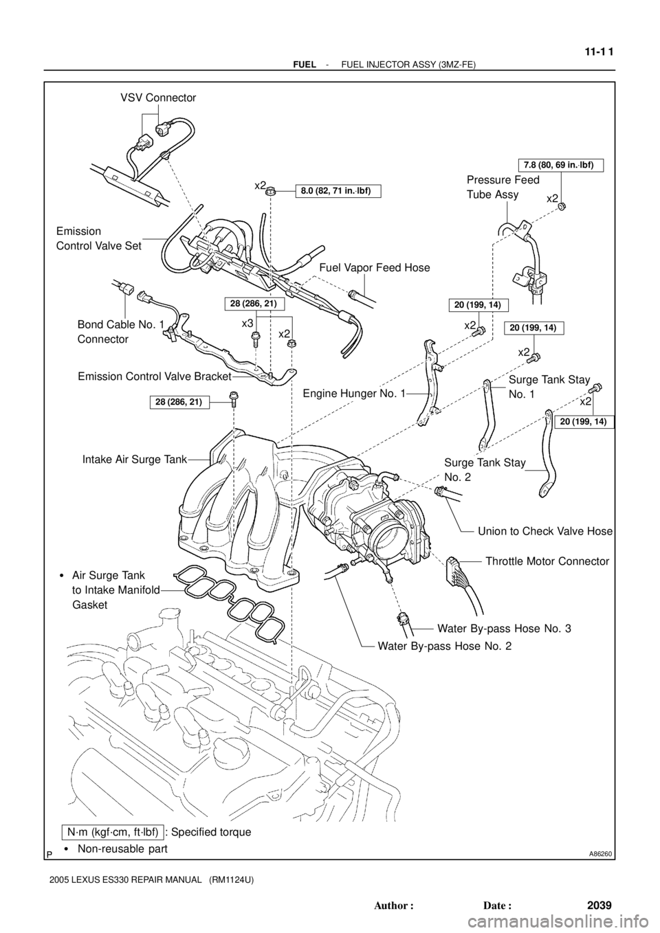
A86260� Non-reusable part
: Specified torque VSV Connector
8.0 (82, 71 in.Vlbf)x2
Emission
Control Valve Set
Emission Control Valve Bracket
Intake Air Surge Tank
� Air Surge Tank
to Intake Manifold
Gasket
Throttle Motor Connector
Water By-pass Hose No. 3
Water By-pass Hose No. 2
N´m (kgf´cm, ft´lbf)
Union to Check Valve Hose
Fuel Vapor Feed Hose
x2 x3
Engine Hunger No. 1Surge Tank Stay
No. 1
Surge Tank Stay
No. 2
20 (204, 14)
20 (204, 14)
20 (204, 14)
7.8 (80, 69 in.Vlbf)
x2
x2 Pressure Feed
Tube Assy
28 (286, 21)
x2
x2
Bond Cable No. 1
Connector
28 (286, 21)
10-14
- ENGINE CONTROL SYSTEMKNOCK SENSOR (3MZ-FE)
2019 Author�: Date�:
2005 LEXUS ES330 REPAIR MANUAL (RM1124U)
Page 573 of 969

(b)
(b)
(b)
(b)
A86263
Fuel Pipe
Clamp
Pinch
Pinch
Pull Out
A75650
Tube Connector
Pipe O-ring Nylon Tube
Quick Connector
A86264
(b) 10-16
- ENGINE CONTROL SYSTEMKNOCK SENSOR (3MZ-")
100J7-02
A86262
(a)
(b)
(b)
(b)
(b)
A86263
Fuel Pipe
Clamp
Pinch
Pinch
Pull Out
A75650
Tube Connector
Pipe O-ring Nylon Tube
Quick Connector
A86264
(b) 10-16
- ENGINE CONTROL SYSTEMKNOCK SENSOR (3MZ-FE)
2021 Author�: Date�:
2005 LEXUS ES330 REPAIR MANUAL (RM1124U)
REPLACEMENT
1. DISCHARGE FUEL SYSTEM PRESSURE (See page 11-1)
2. DISCONNECT ENGINE WIRE NO. 3 (BATTERY NEGATIVE TERMINAL)
3. DRAIN ENGINE COOLANT (See page 16-9)
4. REMOVE FRONT SUSPENSION UPPER BRACE CENTER (W/O TEMS) (See page 10-1 1)
5. REMOVE V-BANK COVER SUB-ASSY (See page 10-1 1)
6. REMOVE AIR CLEANER CAP SUB-ASSY (See page 10-1 1)
7. REMOVE EMISSION CONTROL VALVE SET (See page 11-13)
8. REMOVE INTAKE AIR SURGE TANK (See page 11-13)
9. REMOVE ENGINE MOVING CONTROL ROD
(a) Remove the pipe from the clamp.
(b) Remove the 4 bolts, then remove the engine moving con-
trol rod and radio setting condenser.
10. REMOVE INTAKE MANIFOLD
(a) Disconnect the fuel pipe No. 1.
(1) Remove the fuel pipe clamp.
(2) Pinch the tube connector, then pull out the fuel pipe
No. 1.
NOTICE:
�Check around the quick connector for dirt or mud be-
fore this operation. Remove the dirt if necessary.
�Be careful of mud because the quick connector has
an O-ring which seals the pipe and quick connector
that can be contaminated.
�Do not use any tools in this operation.
�Do not bend or twist the nylon tube. Protect the quick
connector by covering it with a vinyl or plastic bag.
�When the pipe and quick connector are stuck, push
and pull the quick connector to release and pull the
quick connector out carefully.
(b) Disconnect the heater inlet water hose.
Page 581 of 969

11-1
2029 Author�: Date�:
2005 LEXUS ES330 REPAIR MANUAL (RM1124U)
FUEL SYSTEM (3MZ-FE)
PRECAUTION
1. PRECAUTION
(a) Before working o")
110XR-01
A62391
Circuit Opening Relay
- FUELFUEL SYSTEM (3MZ-FE)
11-1
2029 Author�: Date�:
2005 LEXUS ES330 REPAIR MANUAL (RM1124U)
FUEL SYSTEM (3MZ-FE)
PRECAUTION
1. PRECAUTION
(a) Before working on the fuel system, disconnect the engine wire No. 3 (battery negative terminal) from
battery.
(b) Do not smoke or work near open flame when working on the fuel system.
(c) Keep gasoline away from the rubber or leather parts.
2. DISCHARGE FUEL SYSTEM PRESSURE
CAUTION:
�Do not disconnect any parts of the fuel system pres-
sure until you have discharging the fuel system pres-
sure.
�Even after discharge the fuel pressure, place a shop
rag over fittings as you separate them in order to re-
duce risk of fuel spray on yourself or in the engine
compartment.
(a) Disconnect the engine wire No. 3 (battery negative termi-
nal).
(b) Remove the circuit opening relay from the engine room
relay block.
(c) Connect the engine wire No. 3 (battery negative terminal).
Torque: 5.4 NVm (55 kgfVcm, 48 in.Vlbf)
(d) Start the engine. After the engine has stopped on its own,
turn the ignition switch OFF.
HINT:
There is a case that DTC P0171 (system to lean) is output.
(e) Check that the engine does not start.
(f) Remove the fuel tank cap, then let the air out of the fuel
tank.
(g) Disconnect battery negative terminal.
(h) Reinstall the circuit opening relay.
3. FUEL SYSTEM
(a) When disconnecting the high fuel pressure line, a large
amount of gasoline will spill out. So observe these proce-
dures.
(1) Work in order to prevent gasoline from spilling out.
(2) Disconnect the fuel pump tube (see page 11-20).
(3) Drain the fuel remaining inside the fuel pump tube.
Page 585 of 969
110XS-01
Fuel Tube Connector
A50710
A60083
Fuel Pipe
Clamp
A
A
B12941
- FUELFUEL SYSTEM (3MZ-FE)
11-5
2033 Author�: Date�:
2005 LEXUS ES330 REPAIR MANUAL (RM1124U)
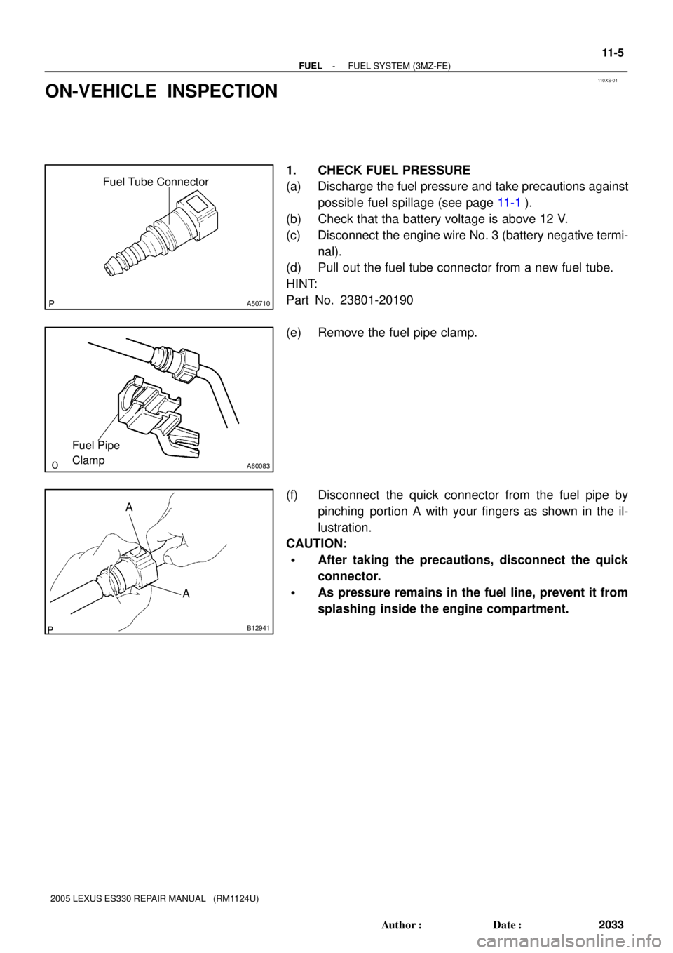
ON-VEHICLE INSPECTION
1. CHECK FUEL PRESSURE
(a) Discharge the fuel pressure and take precautions against
possible fuel spillage (see page 11-1).
(b) Check that tha battery voltage is above 12 V.
(c) Disconnect the engine wire No. 3 (battery negative termi-
nal).
(d) Pull out the fuel tube connector from a new fuel tube.
HINT:
Part No. 23801-20190
(e) Remove the fuel pipe clamp.
(f) Disconnect the quick connector from the fuel pipe by
pinching portion A with your fingers as shown in the il-
lustration.
CAUTION:
�After taking the precautions, disconnect the quick
connector.
�As pressure remains in the fuel line, prevent it from
splashing inside the engine compartment.
Page 586 of 969

SST
(Hose)
Fuel Tube
Connector
Fuel Inlet Tube
SST
(Hose)
A86347DLC3
Hand-held Tester
11-6
- FUELFUEL SYSTEM (3MZ-FE)
2034 Author�: Date�:
2005 LEXUS ES330 REPAIR MANUAL")
A71359
SSTSST
(T-joint)
SST
(Hose)
Fuel Tube
Connector
Fuel Inlet Tube
SST
(Hose)
A86347DLC3
Hand-held Tester
11-6
- FUELFUEL SYSTEM (3MZ-FE)
2034 Author�: Date�:
2005 LEXUS ES330 REPAIR MANUAL (RM1124U)
(g) Install SST (a pressure gauge) and fuel tube connector
using SST as shown in the illustration.
SST 09268-41047 (95336-08070), 09268-45014
(09268-41250, 09268-41200, 09268-41220)
(h) Wipe up any gasoline.
(i) Reconnect the engine wire No. 3 (battery negative termi-
nal).
(j) Connect the hand-hand tester to the DLC3.
(k) Measure the fuel pressure.
Fuel pressure:
304 to 343 kPa (3.1 to 3.5 kgf/cm
2, 44 to 50 psi)
If the pressure is high, replace the fuel pressure regulator.
If the pressure is low, check the fuel hose connections, fuel
pump, fuel filter and fuel pressure regulator.
(l) Disconnect the hand-held tester from the DLC3.
(m) Start the engine.
(n) Measure the fuel pressure at idle.
Fuel pressure:
304 to 343 kPa (3.1 to 3.5 kgf/cm
2, 44 to 50 psi)
(o) Stop the engine.
(p) Check that the fuel pressure remains as specified for 5
minutes after the engine has stopped.
Fuel pressure: 147 kPa (1.5 kgf/cm
2, 21 psi) or more
If the pressure is not as specified, check the fuel pump, pres-
sure regulator and/or fuel injectors.
(q) After checking the fuel pressure, disconnect the battery
negative terminal and carefully remove SST and the fuel
tube connector to prevent gasoline splash.
(r) Reconnect the No. 1 fuel pipe (the fuel tube connector).
CAUTION:
After taking the precautions, connect the quick connector.
Page 588 of 969

B12947
A86391
SST
(Hose)
SST
(Union)
O-ring
Vinyl TubeSST
(Clamp)
11-8
- FUELFUEL SYSTEM (3MZ-FE)
2036 Author�: Date�:
2005 LEXUS")
110XT-02
Fuel Tube Connector
A50710
Fuel Tube Connector
SST
(Hose)
B12947
A86391
SST
(Hose)
SST
(Union)
O-ring
Vinyl TubeSST
(Clamp)
11-8
- FUELFUEL SYSTEM (3MZ-FE)
2036 Author�: Date�:
2005 LEXUS ES330 REPAIR MANUAL (RM1124U)
INSPECTION
1. INSPECT FUEL INJECTOR ASSY
(a) Inspect the resistance.
(1) Using an ohmmeter, measure the resistance be-
tween the terminals.
Standard:
Tester ConnectionSpecified Condition
1 - 213.4 to 14.2 W at 20�C (68�F)
If the resistance is not as specified, replace the fuel injector.
(b) Check the operation.
CAUTION:
�This test involves high-pressure fuel and electricity.
Keep the injector free of sparks during the test.
�Take every precaution regarding safe handling of
both the fuel and electricity.
�Perform this test in a safe area, and avoid any sparks
or flame.
�Do not smoke.
(1) Pull out the fuel tube connector from a new fuel
tube.
HINT:
Part No. 23801 - 20190
(2) Connect SST and the fuel tube connector to the fuel
pipe.
SST 09268-41047 (95336-08070)
CAUTION:
After taking the precautions, connect the quick connector.
(3) Install the grommet and O-ring to the fuel injector.
(4) Connect SST (a union and hose) to the fuel injector,
then hold the fuel injector and union with SST (a
clamp).
SST 09268- 41047 (09268- 41110, 09268- 41300,
95336-08070)
(5) Put the fuel injector into a graduated cylinder.
HINT:
Install a suitable vinyl tube to the fuel injector to contain the gas-
oline spray.
Page 591 of 969
A86260� Non-reusable part
: Specified torque VSV Connector
8.0 (82, 71 in.Vlbf)x2
Emission
Control Valve Set
Emission Control Valve Bracket
Intake Air Surge Tank
� Air Surge Tank
to Intake Manifold
Gasket
Throttle Motor Connector
Water By-pass Hose No. 3
Water By-pass Hose No. 2
N´m (kgf´cm, ft´lbf)
Union to Check Valve Hose
Fuel Vapor Feed Hose
x2 x3
Engine Hunger No. 1Surge Tank Stay
No. 1
Surge Tank Stay
No. 2
20 (199, 14)
20 (199, 14)
20 (199, 14)
7.8 (80, 69 in.Vlbf)
x2
x2 Pressure Feed
Tube Assy
28 (286, 21)
x2
x2
Bond Cable No. 1
Connector
28 (286, 21)
- FUELFUEL INJECTOR ASSY (3MZ-FE)
11-1 1
2039 Author�: Date�:
2005 LEXUS ES330 REPAIR MANUAL (RM1124U)