Page 342 of 969

3305M-03
C64523
Contract
F06409
F40318
33-16
- PARKING BRAKEPARKING BRAKE ASSY
2512 Author�: Date�:
PARKING BRAKE ASSY
OVERHAUL
HINT:
�COMPONENTS: See page 33-3
�Overhaul the RH side by the same procedures with LH side.
1. REMOVE REAR WHEEL
2. REMOVE REAR DISC BRAKE CALIPER ASSY LH
(a) Remove the 2 bolts and separate the rear disc brake caliper assy LH.
HINT:
Do not disconnect the flexible hose from the brake caliper.
3. REMOVE REAR DISC
(a) Release the parking brake, and remove the rear disc.
HINT:
�Put matchmarks on the disc and the axle hub.
�If the disc cannot be removed easily, turn the shoe adjust-
er until the wheel turns freely.
4. INSPECT BRAKE DISC INSIDE DIAMETER
(a) Using a brake drum gauge or equivalent, measure the in-
side diameter of the disc.
Standard inside diameter: 170 mm (6.69 in.)
Maximum inside diameter: 171 mm (6.73 in.)
5. REMOVE PARKING BRAKE SHOE RETURN TENSION
SPRING
(a) Using a needle-nose pliers, remove the 2 return tension
springs.
6. REMOVE PARKING BRAKE SHOE STRUT COMPRESSION SPRING
(a) Slide out the front shoe and remove the compression spring.
7. REMOVE PARKING BRAKE SHOE STRUT LH
Page 344 of 969
 Install the shoe lever and shim to the rear shoe with a new
C-washer .
(b) Using a")
R00343
C80705
F40318
33-18
- PARKING BRAKEPARKING BRAKE ASSY
2514 Author�: Date�:
12. INSTALL PARKING BRAKE SHOE
(a) Install the shoe lever and shim to the rear shoe with a new
C-washer .
(b) Using a feeler gauge, measure the clearance.
Standard clearance: Less than 0.35 mm (0.0138 in.)
If the clearance is not within the specification, replace the shim
with one of the correct size.
Shim ThicknessShim Thickness
0.3 mm (0.012 in.)0.9 mm (0.035 in.)
0.6 mm (0.024 in.)-
(c) Apply the high temperature grease to the adjusting bolt.
(d) Install the shoe adjusting screw set and tension spring to
the front and rear shoe.
(e) Install the 2 pins, 4 cups and 2 shoe hold-down springs.
(f) Connect the parking brake cable to the shoe lever.
(g) Install the front and rear parking brake shoe.
13. INSTALL PARKING BRAKE SHOE STRUT LH
14. INSTALL PARKING BRAKE SHOE STRUT COMPRESSION SPRING
15. INSTALL PARKING BRAKE SHOE RETURN TENSION
SPRING
(a) Using a needle nose pliers, install the 2 return tension
springs.
Page 352 of 969
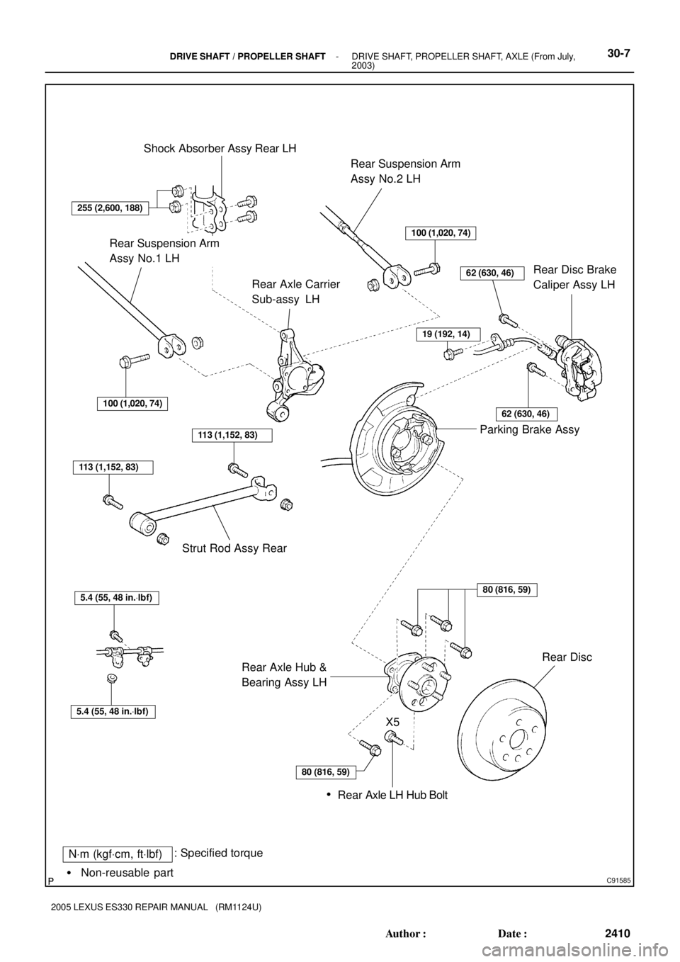
C91585
NVm (kgfVcm, ftVlbf): Specified torque
� Non-reusable partShock Absorber Assy Rear LH
Rear Suspension Arm
Assy No.2 LH
Rear Disc Brake
Caliper Assy LH Rear Axle Carrier
Sub-assy LH
Parking Brake Assy
Rear Axle Hub &
Bearing Assy LHRear Disc Strut Rod Assy Rear
100 (1,020, 74)
62 (630, 46)
100 (1,020, 74)
113 (1,152, 83)
113 (1,152, 83)
5.4 (55, 48 in.Vlbf)
5.4 (55, 48 in.Vlbf)
Rear Axle LH Hub Bolt
80 (816, 59)
X5
�
255 (2,600, 188)
19 (192, 14)
62 (630, 46)
80 (816, 59)
Rear Suspension Arm
Assy No.1 LH
- DRIVE SHAFT / PROPELLER SHAFTDRIVE SHAFT, PROPELLER SHAFT, AXLE (From July,
2003)30-7
2410 Author�: Date�:
2005 LEXUS ES330 REPAIR MANUAL (RM1124U)
Page 374 of 969

REAR AXLE CARRIER SUB-ASSY LH
REPLACEME")
3006J-06
C83017
C83018
C83019
- DRIVE SHAFT / PROPELLER SHAFTREAR AXLE CARRIER SUB-ASSY LH
30-29
2432 Author�: Date�:
2005 LEXUS ES330 REPAIR MANUAL (RM1124U)
REAR AXLE CARRIER SUB-ASSY LH
REPLACEMENT
HINT:
�COMPONENTS: See page 30-4
�Replace the RH side by the same procedures with the LH side.
1. REMOVE REAR WHEEL
2. REMOVE STRUT ROD ASSY REAR (SEE PAGE 27-18)
3. DISCONNECT REAR DISC BRAKE CALIPER ASSY LH (SEE PAGE 30-26)
4. REMOVE REAR DISC
5. DISCONNECT SKID CONTROL SENSOR WIRE
6. REMOVE REAR AXLE HUB & BEARING ASSY LH (SEE PAGE 30-26)
7. SEPARATE REAR SUSPENSION ARM ASSY NO.2 LH
(a) Remove the bolt, nut and rear suspension arm assy No.2
LH from the rear axle carrier sub-assy LH.
HINT:
While fixing the nut, turn and remove the bolt.
8. SEPARATE REAR SUSPENSION ARM ASSY NO.1 LH
(a) Remove the bolt, nut and rear suspension arm assy No.1
LH from the rear axle carrier sub-assy LH.
HINT:
While fixing the nut, turn and remove the bolt.
9. REMOVE REAR AXLE CARRIER SUB-ASSY LH
(a) Remove the 2 bolts, nuts and rear axle carrier sub-assy
LH from the shock absorber assy rear LH.
NOTICE:
When removing bolt, stop the bolt from rotating and loosen
the nut.
Page 375 of 969

10. INSTALL REAR AXLE CARRIER SUB-ASSY LH
(a) In")
C83019
C83018
C83017
30-30
- DRIVE SHAFT / PROPELLER SHAFTREAR AXLE CARRIER SUB-ASSY LH
2433 Author�: Date�:
2005 LEXUS ES330 REPAIR MANUAL (RM1124U)
10. INSTALL REAR AXLE CARRIER SUB-ASSY LH
(a) Install the rear axle carrier sub-assy LH with the 2 bolts
and nuts.
Torque: 255 NVm (2,600 kgfVcm, 188 ftVlbf)
NOTICE:
When installing bolt, stop the bolt from rotating and torque
the nut.
HINT:
Insert the bolt from the rear side of the vehicle and install the
nut.
11. TEMPORARILY TIGHTEN REAR SUSPENSION ARM
ASSY NO.1 LH
(a) Install the rear suspension arm assy No.1 LH to the rear
axle carrier sub-assy LH with the bolt and nut, temporarily
tighten the bolt.
HINT:
Insert the bolt from the front side of the vehicle and while fixing
the nut, turn and install the bolt.
12. TEMPORARILY TIGHTEN REAR SUSPENSION ARM
ASSY NO.2 LH
(a) Install the rear suspension arm No.2 to the rear axle carri-
er sub-assy LH with the bolt and nut, temporarily tighten
the bolt.
HINT:
Insert the bolt from the rear side of the vehicle and while fixing
the nut, turn and install the bolt.
13. INSTALL REAR AXLE HUB & BEARING ASSY LH (SEE PAGE 30-26)
14. INSTALL SKID CONTROL SENSOR WIRE
15. INSTALL REAR DISC
16. INSTALL REAR DISC BRAKE CALIPER ASSY LH (SEE PAGE 30-26)
17. TEMPORARILY TIGHTEN STRUT ROD ASSY REAR (SEE PAGE 27-18)
18. STABILIZE SUSPENSION (SEE PAGE 27-18)
19. FULLY TIGHTEN REAR SUSPENSION ARM ASSY NO.1 LH (SEE PAGE 27-10)
20. FULLY TIGHTEN REAR SUSPENSION ARM ASSY NO.2 LH (SEE PAGE 27-14)
21. FULLY TIGHTEN STRUT ROD ASSY REAR (SEE PAGE 27-18)
22. INSTALL REAR WHEEL
Torque: 103 NVm (1,050 kgfVcm, 76 ftVlbf)
23. INSPECT AND ADJUST REAR WHEEL ALIGNMENT (SEE PAGE 27-3)
24. CHECK ABS SPEED SENSOR SIGNAL
w/ VSC (SEE PAGE 05-471)
w/o VSC (SEE PAGE 05-420)
Page 412 of 969
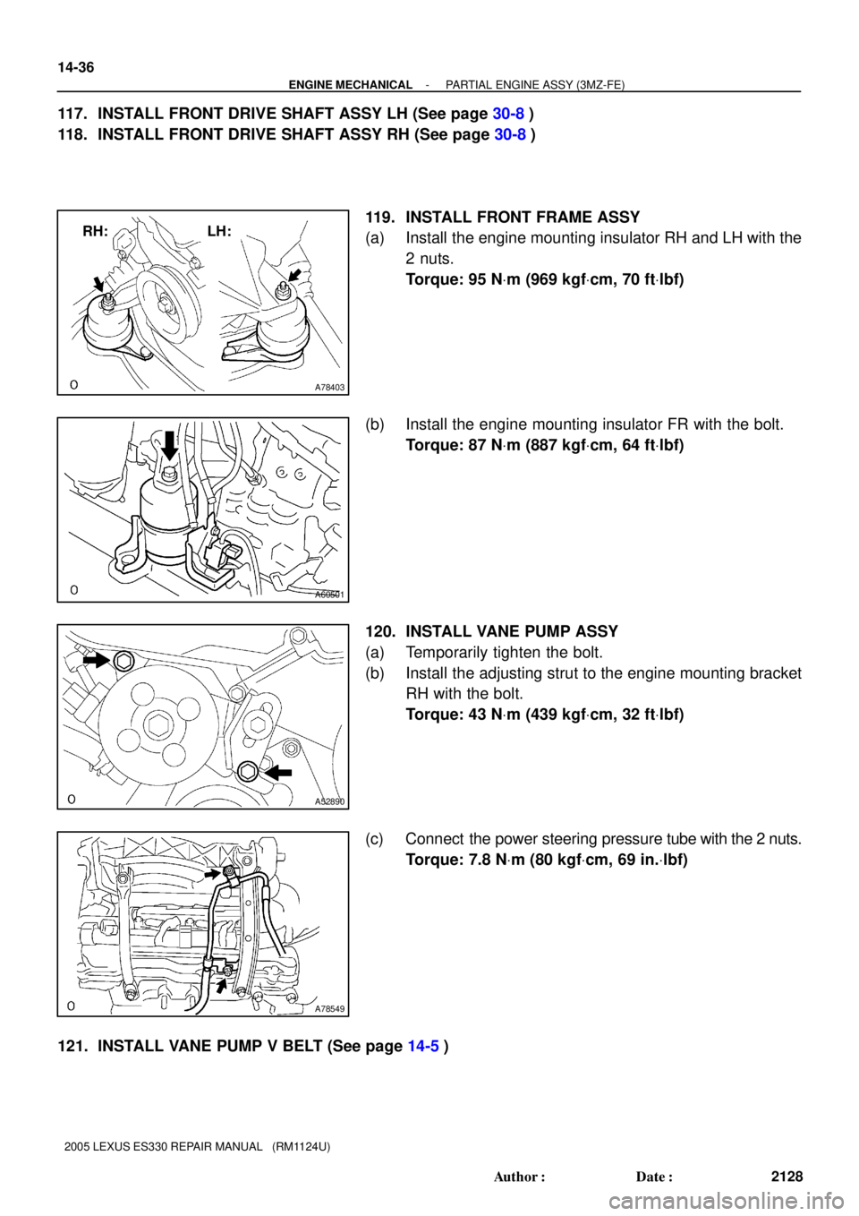
A78403
RH: LH:
A60501
A52890
A78549
14-36
- ENGINE MECHANICALPARTIAL ENGINE ASSY (3MZ-FE)
2128 Author�: Date�:
2005 LEXUS ES330 REPAIR MANUAL (RM1124U)
117. INSTALL FRONT DRIVE SHAFT ASSY LH (See page 30-8)
118. INSTALL FRONT DRIVE SHAFT ASSY RH (See page 30-8)
119. INSTALL FRONT FRAME ASSY
(a) Install the engine mounting insulator RH and LH with the
2 nuts.
Torque: 95 NVm (969 kgfVcm, 70 ftVlbf)
(b) Install the engine mounting insulator FR with the bolt.
Torque: 87 NVm (887 kgfVcm, 64 ftVlbf)
120. INSTALL VANE PUMP ASSY
(a) Temporarily tighten the bolt.
(b) Install the adjusting strut to the engine mounting bracket
RH with the bolt.
Torque: 43 NVm (439 kgfVcm, 32 ftVlbf)
(c) Connect the power steering pressure tube with the 2 nuts.
Torque: 7.8 NVm (80 kgfVcm, 69 in.Vlbf)
121. INSTALL VANE PUMP V BELT (See page 14-5)
Page 708 of 969

26-5
2368 Author�: Date�:
2005 LEXUS ES330 REPAIR MANUAL (RM1124U)
FRO")
2605T-05
C91608
B Front:A
C91609
C Rear:
D
SA3213
A
DB
Front
C
F40165
- FRONT SUSPENSIONFRONT WHEEL ALIGNMENT (From July, 2003)
26-5
2368 Author�: Date�:
2005 LEXUS ES330 REPAIR MANUAL (RM1124U)
FRONT WHEEL ALIGNMENT (From July, 2003)
ADJUSTMENT
1. INSPECT TIRE (See page 26-5)
2. MEASURE VEHICLE HEIGHT
Vehicle height:
FrontA - B: 120 mm (4.72 in.)
RearD - C: 52 mm (2.05 in.)
Measuring points:
A: Ground clearance of front wheel center
B: Ground clearance of lower suspension arm No. 2 set bolt
center
C: Ground clearance of strut rod set bolt center
D: Ground clearance of rear wheel center
NOTICE:
Before inspecting the wheel alignment, adjust the vehicle
height to the specified value.
HINT:
Bounce the vehicle at the corners up and down to stabilize the
suspension and inspect the vehicle height.
3. INSPECT TOE-IN
Toe-in:
Toe-in
(total)A + B: 0° ± 12' (0° ± 0.2°)
C - D: 0 ± 2 mm (0 ± 0.08 in.)
If the toe-in is not within the specified value, adjust it at the rack
ends.
4. ADJUST TOE-IN
(a) Remove the rack boot set clips.
(b) Loosen the tie rod end lock nuts.
(c) Turn the right and left rack ends by an equal amount to
adjust the toe-in.
HINT:
Try to adjust the toe-in to the center of the specified value.
(d) Make sure that the lengths of the right and left rack ends
are the same.
(e) Torque the tie rod end lock nuts.
Torque: 74 N´m (755 kgf´cm, 55 ft´lbf)
(f) Place the boots on the seats and install the clips.
HINT:
Make sure that the boots are not twisted.
(g) Perform VSC system calibration. (See page 05-471)
Page 764 of 969
2704V-06
C92643
Rear Suspension Member
Sub-Assy
Rear Suspension Support
No. 1 Cover LH
Collar
Suspension Support
Spring Bumper
Coil Spring
Lower Insulator Rear Suspension
Arm Assy No. 2 LH
Rear Suspension
Arm Assy No. 1 LH
Strut Rod Assy Rear
Bracket
Bushing
Shock Absorber
Assy Rear LH Rear Stabilizer
Link Assy LH Stabilizer Bar Rear Parking Brake Cable
NVm (kgfVcm, ftVlbf) : Specified torque
49 (500, 36)
39 (400, 29)
55 (561, 41)
100 (1,020, 74)
100 (1,020, 74)
113 (1,150, 83)
39 (400, 29)
19 (195, 14)
5.4 (55, 48 in.Vlbf)
255 (2,600, 188)
113 (1,150, 83)
100 (1,020, 74)
100 (1,020, 74)
55 (561, 41)
38 (387, 28)
RH Side:
w/TEMS:
19 (195, 14)
�
�Non-reusable partw/o TEMS:5.4 (55, 48 in.Vlbf)
27-2
- REAR SUSPENSIONREAR SUSPENSION
2384 Author�: Date�:
2005 LEXUS ES330 REPAIR MANUAL (RM1124U)
REAR SUSPENSION
COMPONENTS