Page 3073 of 3419
SE-108
REAR SEAT
Revision: October 20052005 QX56
Second row center
WIIA0410E
1. Seatback pad 2. Armrest finisher 3. Headrest
4. Seat belt retractor cover 5. Seat belt bezel 6. RH headrest guide locking
Page 3074 of 3419
REAR SEAT
SE-109
C
D
E
F
G
H
J
K
L
MA
B
SE
Revision: October 20052005 QX56
7. LH headrest guide free 8. Seatback board 9. Seat bracket cover
10. Armrest pivot bracket cover 11. Seatback frame 12. Seat cushion frame
13. Latch assembly 14. Lower rear pivot bracket support 15. Outer hinge cover
16. Center seat base assembly 17. Link and pivot bracket apron 18. Seat cushion pad
19. Seat cushion trim cover 20. Cushion stop bumper 21. Inner lever cover
22. Seat hinge assembly 23. Seat lever assembly 24 Outer lever cover
25. Seat lock cover 26 Armrest cover 27 Armrest bracket
28 Armrest pad 29 Cup holder 30 Seatback trim cover
Page 3077 of 3419
SE-112
REAR SEAT
Revision: October 20052005 QX56
Third row
WIIA0412E
1. Headrests 2. Release handle and cable 3. Tether anchor plate
4. Headrest locking guide 5. Headrest guide free 6. Seatback panel
Page 3083 of 3419
SRS-4
PREPARATION
Revision: October 20052005 QX56
PREPARATIONPFP:00002
Special Service ToolsEHS0016E
The actual shapes of Kent-Moore tools may differ from those of special service tools illustrated here.
Commercial Service ToolsEHS0016F
Tool number
(Kent-Moore No.)
Tool nameDescription
—
(J-42057)
Air bag lock master key setRemoving and installing air bag lock
LRS210
Tool name
(Kent-Moore No.)Description
Steering wheel puller
(J-1859A)Removing steering wheel
Steering wheel puller legs
(J-42578)Removing steering wheel
LHIA0043E
LHIA0044E
Page 3086 of 3419

SUPPLEMENTAL RESTRAINT SYSTEM (SRS)
SRS-7
C
D
E
F
G
I
J
K
L
MA
B
SRS
Revision: October 20052005 QX56
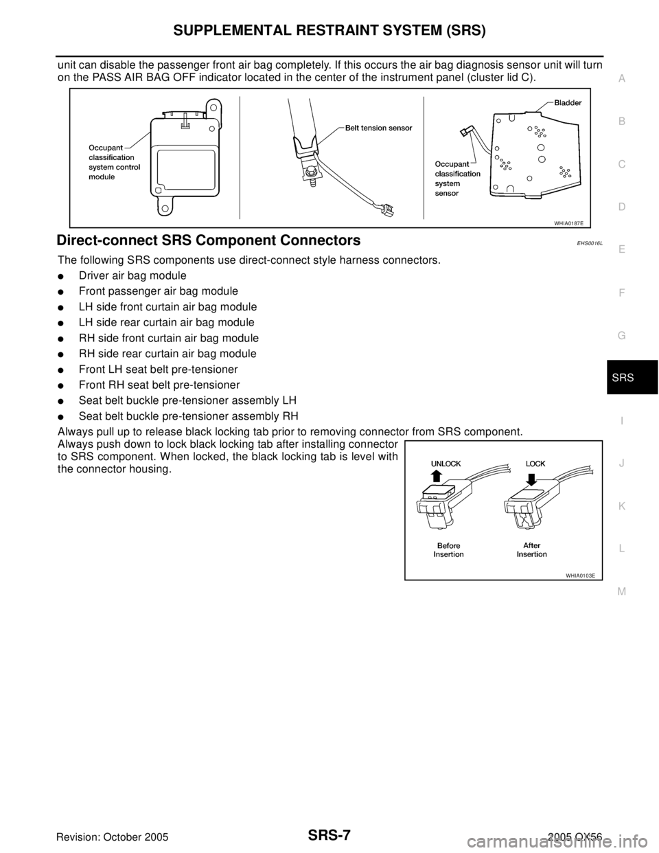
unit can disable the passenger front air bag completely. If this occurs the air bag diagnosis sensor unit will turn
on the PASS AIR BAG OFF indicator located in the center of the instrument panel (cluster lid C).
Direct-connect SRS Component ConnectorsEHS0016L
The following SRS components use direct-connect style harness connectors.
�Driver air bag module
�Front passenger air bag module
�LH side front curtain air bag module
�LH side rear curtain air bag module
�RH side front curtain air bag module
�RH side rear curtain air bag module
�Front LH seat belt pre-tensioner
�Front RH seat belt pre-tensioner
�Seat belt buckle pre-tensioner assembly LH
�Seat belt buckle pre-tensioner assembly RH
Always pull up to release black locking tab prior to removing connector from SRS component.
Always push down to lock black locking tab after installing connector
to SRS component. When locked, the black locking tab is level with
the connector housing.
WHIA0187E
WHIA0103E
Page 3123 of 3419

SRS-44
TROUBLE DIAGNOSIS
Revision: October 20052005 QX56
Trouble Diagnosis: “AIR BAG” Warning Lamp Does Not Turn OffEHS0016V
DIAGNOSTIC PROCEDURE 6
1. CHECK CONDITION OF AIR BAG MODULE
Inspect for any deployed air bag modules or seat belt pre-tensioners.
Are any air bag modules or seat belt pre-tensioners deployed?
Yes >> Refer to SRS-61, "COLLISION DIAGNOSIS" .
No >> GO TO 2.
2. CHECK THE AIR BAG FUSE
Check 10A fuse [No. 13, located in the fuse block (J/B)].
Refer to PG-4, "
POWER SUPPLY ROUTING CIRCUIT" .
OK or NG
OK >> GO TO 4.
NG >> GO TO 3.
3. CHECK AIR BAG FUSE AGAIN
Replace 10A fuse [No. 13, located in the fuse block (J/B)] and turn ignition switch ON.
Does the fuse blow again?
Yes >> Repair main harness.
No >> Inspection End.
4. CHECK AIR BAG DIAGNOSIS SENSOR UNIT
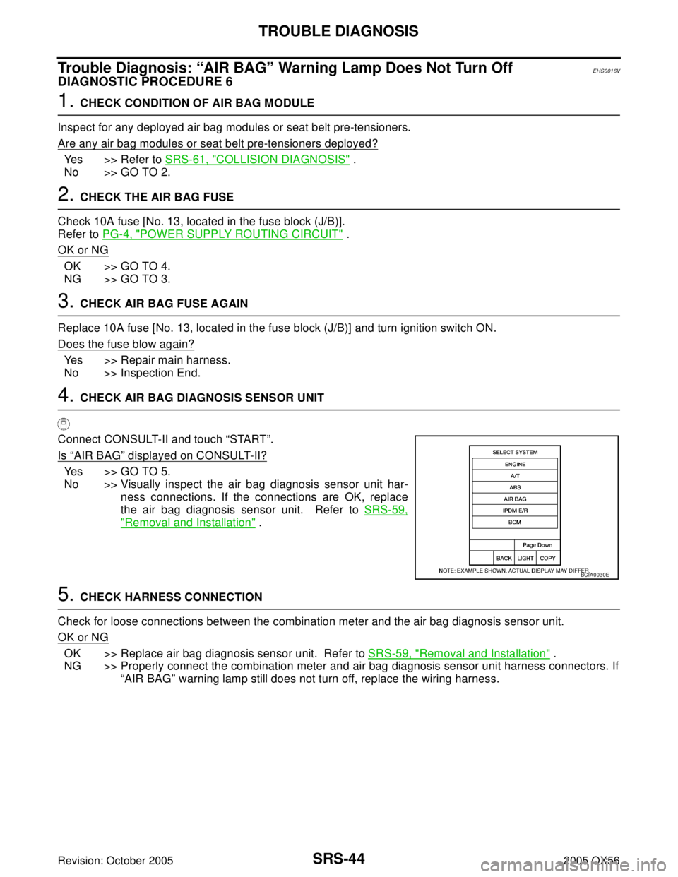
Connect CONSULT-II and touch “START”.
Is
“AIR BAG” displayed on CONSULT-II?
Yes >> GO TO 5.
No >> Visually inspect the air bag diagnosis sensor unit har-
ness connections. If the connections are OK, replace
the air bag diagnosis sensor unit. Refer to SRS-59,
"Removal and Installation" .
5. CHECK HARNESS CONNECTION
Check for loose connections between the combination meter and the air bag diagnosis sensor unit.
OK or NG
OK >> Replace air bag diagnosis sensor unit. Refer to SRS-59, "Removal and Installation" .
NG >> Properly connect the combination meter and air bag diagnosis sensor unit harness connectors. If
“AIR BAG” warning lamp still does not turn off, replace the wiring harness.
BCIA0030E
Page 3124 of 3419
TROUBLE DIAGNOSIS
SRS-45
C
D
E
F
G
I
J
K
L
MA
B
SRS
Revision: October 20052005 QX56
Trouble Diagnosis: “AIR BAG” Warning Lamp Does Not Turn OnEHS0016W
DIAGNOSTIC PROCEDURE 7
1. CHECK METER FUSE
Check the 10A fuse [No. 14, located in the fuse block (J/B)].
Refer to PG-4, "
POWER SUPPLY ROUTING CIRCUIT" .
OK or NG
OK >> GO TO 3.
NG >> GO TO 2.
2. CHECK METER FUSE AGAIN
Replace 10A fuse [No. 14, located in the fuse block (J/B)] and turn ignition switch ON.
Does the fuse blow again?
Yes >> Repair the related harness.
No >> Inspection End.
3. CHECK HARNESS CONNECTION BETWEEN AIR BAG DIAGNOSIS SENSOR UNIT AND COMBINA-
TION METER
Disconnect the air bag diagnosis sensor unit harness connectors and turn ignition switch ON.
Does
“AIR BAG” warning lamp turn on?
Yes >> Replace the air bag diagnosis sensor unit. Refer to SRS-59, "Removal and Installation" .
No >> Check the combination meter ground circuits.
Page 3128 of 3419

SPIRAL CABLE
SRS-49
C
D
E
F
G
I
J
K
L
MA
B
SRS
Revision: October 20052005 QX56
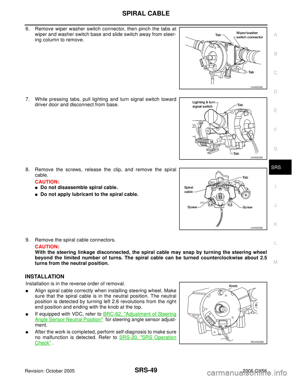
6. Remove wiper washer switch connector, then pinch the tabs at
wiper and washer switch base and slide switch away from steer-
ing column to remove.
7. While pressing tabs, pull lighting and turn signal switch toward
driver door and disconnect from base.
8. Remove the screws, release the clip, and remove the spiral
cable.
CAUTION:
�Do not disassemble spiral cable.
�Do not apply lubricant to the spiral cable.
9. Remove the spiral cable connectors.
CAUTION:
With the steering linkage disconnected, the spiral cable may snap by turning the steering wheel
beyond the limited number of turns. The spiral cable can be turned counterclockwise about 2.5
turns from the neutral position.
INSTALLATION
Installation is in the reverse order of removal.
�Align spiral cable correctly when installing steering wheel. Make
sure that the spiral cable is in the neutral position. The neutral
position is detected by turning left 2.6 revolutions from the right
end position and ending with the knob at the top.
�If equipped with VDC, refer to BRC-62, "Adjustment of Steering
Angle Sensor Neutral Position" for steering angle sensor adjust-
ment.
�After the work is completed, perform self-diagnosis to make sure
no malfunction is detected. Refer to SRS-20, "
SRS Operation
Check" .
LHIA0034E
LHIA0035E
LHIA0036E
WGIA0038E