Page 3218 of 3419

TROUBLE DIAGNOSIS FOR SYSTEM
TF-75
C
E
F
G
H
I
J
K
L
MA
B
TF
Revision: October 20052005 QX56
6. CHECK ACTUATOR MOTOR
1. Remove transfer control device. Refer to TF-138, "
Removal and Installation" .
2. Check operation by applying battery voltage to transfer control
device (actuator motor) terminals 21 and 24.
CAUTION:
�Do not operate actuator motor for more than 1 second.
�Change the actuator motor position to “HIGH” when
installing.
�Be careful not to overheat the harness.
3. Check continuity between transfer control device (actuator
motor) terminals 21 and 24.
OK or NG
OK >> GO TO 7.
NG >> Replace transfer control device (actuator motor). Refer
to TF-138, "
Removal and Installation" .
7. CHECK TRANSFER CONTROL UNIT
Check transfer control unit input/output signal. Refer to TF-36, "
Transfer Control Unit Input/Output Signal Ref-
erence Values" .
OK or NG
OK >> GO TO 8.
NG >> Check transfer control unit pin terminals for damage or loose connection with harness connector.
If any items are damaged, repair or replace damaged parts.
8. CHECK DTC
Perform the self-diagnosis, after driving a vehicle for a while.
OK or NG
OK >> Inspection End.
NG >> Replace transfer control unit. Refer to TF-132, "
Removal and Installation" .
Terminal Actuator motor
21 (Battery voltage) - 24 (Ground) Clockwise rotate
24 (Battery voltage) - 21 (Ground) Counterclockwise rotate
21 - 24 : Approx. 0.2 Ω
WDIA0224E
SDIA2726E
Page 3219 of 3419

2. Remove transfer shift")
TF-76
TROUBLE DIAGNOSIS FOR SYSTEM
Revision: October 20052005 QX56
COMPONENT INSPECTION
Transfer Shift Relay
1. Turn ignition switch “OFF”. (Stay for at least 5 seconds.)
2. Remove transfer shift high relay and transfer shift low relay. Refer to TF-22, "
Location of Electrical Parts" .
3. Apply 12V direct current between transfer shift relay terminals 1
and 2.
4. Check continuity between relay terminals 3 and 4, 3 and 5.
5. If NG, replace transfer shift relay.
Transfer Control Device
1. Remove transfer control device. Refer to TF-138, "Removal and Installation" .
2. Check operation by applying battery voltage to transfer control
device (actuator motor) terminals 21 and 24.
CAUTION:
�Do not operate actuator motor for more than 1 second.
�Change the actuator motor position to “HIGH” when
installing.
�Be careful not to overheat the harness.
3. Check continuity between transfer control device (actuator
motor) terminals 21 and 24.
4. If NG, replace transfer control device (actuator motor). Refer to
TF-138, "
Removal and Installation" .
Terminal Condition Continuity
3 - 412V direct current supply between terminals 1 and 2 No
OFF Yes
3 - 512V direct current supply between terminals 1 and 2 Yes
OFF No
LDIA0099E
Terminal Actuator motor
21 (Battery voltage) - 24 (Ground) Clockwise rotate
24 (Battery voltage) - 21 (Ground) Counterclockwise rotate
21 - 24 : Approx. 0.2 Ω
WDIA0224E
SDIA2726E
Page 3261 of 3419

2. Disconnect tran")
TF-118
TROUBLE DIAGNOSIS FOR SYMPTOMS
Revision: October 20052005 QX56
2. CHECK TRANSFER CONTROL UNIT GROUND CIRCUIT
1. Turn ignition switch “OFF”. (Stay for at least 5 seconds.)
2. Disconnect transfer control unit harness connector.
3. Check continuity between transfer control unit harness connec-
tor E142 terminals 3 (B), 6 (B), E143 terminal 45 (B) and ground.
Also check harness for short to ground and short to power.
OK or NG
OK >> GO TO 3.
NG >> Repair open circuit or short to ground or short to power
in harness or connectors.
3. CHECK COMBINATION METER POWER SUPPLY CIRCUIT
1. Turn ignition switch “OFF”. (Stay for at least 5 seconds.)
2. Disconnect combination meter harness connector.
3. Check voltage between combination meter harness connector
terminal and ground.
4. Turn ignition switch “ON”. (Do not start engine.)
5. Check voltage between combination meter harness connector
terminal and ground.
OK or NG
OK >> GO TO 4.
NG >> Check the following. If any items are damaged, repair or
replace damaged parts.
�10A fuse No. 14 located in the fuse block (J/B). Refer
to PG-4, "
POWER SUPPLY ROUTING CIRCUIT" .
�Harness for short or open between battery and combination meter harness connector M24 ter-
minal 24 (O/L).
�Ignition switch. Refer to PG-4, "POWER SUPPLY ROUTING CIRCUIT" . Continuity should exist.
SDIA2691E
Connector Terminal (Wire color) Voltage (Approx.)
M24 24 (O/L) - Ground 0V
WDIA0151E
Connector Terminal (Wire color) Voltage (Approx.)
M24 24 (O/L) - Ground Battery voltage
WDIA0152E
Page 3265 of 3419

2. Disconnect tran")
TF-122
TROUBLE DIAGNOSIS FOR SYMPTOMS
Revision: October 20052005 QX56
2. CHECK TRANSFER CONTROL UNIT GROUND CIRCUIT
1. Turn ignition switch “OFF”. (Stay for at least 5 seconds.)
2. Disconnect transfer control unit harness connector.
3. Check continuity between transfer control unit harness connec-
tor E142 terminals 3 (B), 6 (B), E143 terminal 45 (B) and ground.
Also check harness for short to ground and short to power.
OK or NG
OK >> GO TO 3.
NG >> Repair open circuit or short to ground or short to power
in harness or connectors.
3. CHECK COMBINATION METER POWER SUPPLY CIRCUIT
1. Turn ignition switch “OFF”. (Stay for at least 5 seconds.)
2. Disconnect transfer control unit harness connector.
3. Check voltage between combination meter harness connector
terminal and ground.
4. Turn ignition switch “ON”. (Do not start engine.)
5. Check voltage between combination meter harness connector
terminal and ground.
OK or NG
OK >> GO TO 4.
NG >> Check the following. If any items are damaged, repair or
replace damaged parts.
�10A fuse No. 14 located in the fuse block (J/B). Refer
to PG-4, "
POWER SUPPLY ROUTING CIRCUIT" .
�Harness for short or open between battery and combination meter harness connector M24 ter-
minal 24 (O/L).
�Ignition switch. Refer to PG-4, "POWER SUPPLY ROUTING CIRCUIT" . Continuity should exist.
SDIA2691E
Connector Terminal (Wire color) Voltage (Approx.)
M24 24 (O/L) - Ground 0V
WDIA0151E
Connector Terminal (Wire color) Voltage (Approx.)
M24 24 (O/L) - Ground Battery voltage
WDIA0152E
Page 3276 of 3419
FRONT OIL SEAL
TF-133
C
E
F
G
H
I
J
K
L
MA
B
TF
Revision: October 20052005 QX56
FRONT OIL SEALPFP:38189
Removal and InstallationEDS0 02 IT
REMOVAL
1. Partially drain the transfer fluid. Refer to MA-24, "DRAINING" .
2. Remove the front propeller shaft. Refer to PR-4, "
Removal and Installation" .
3. Remove the companion flange self-lock nut, using Tool.
4. Put a matching mark on top of the front drive shaft in line with
the mark on the companion flange.
CAUTION:
Use paint to make the matching mark on the front drive
shaft. Do not damage the front drive shaft.
5. Remove the companion flange, using suitable tool.
6. Remove the oil seal from the front case, using Tool.
CAUTION:
Do not damage front case.Tool number : KV40104000 ( — )
SDIA2657E
SDIA2658E
WDIA0193E
Tool number : ST33290001 (J-34286)
LDIA0144E
Page 3277 of 3419
TF-134
FRONT OIL SEAL
Revision: October 20052005 QX56
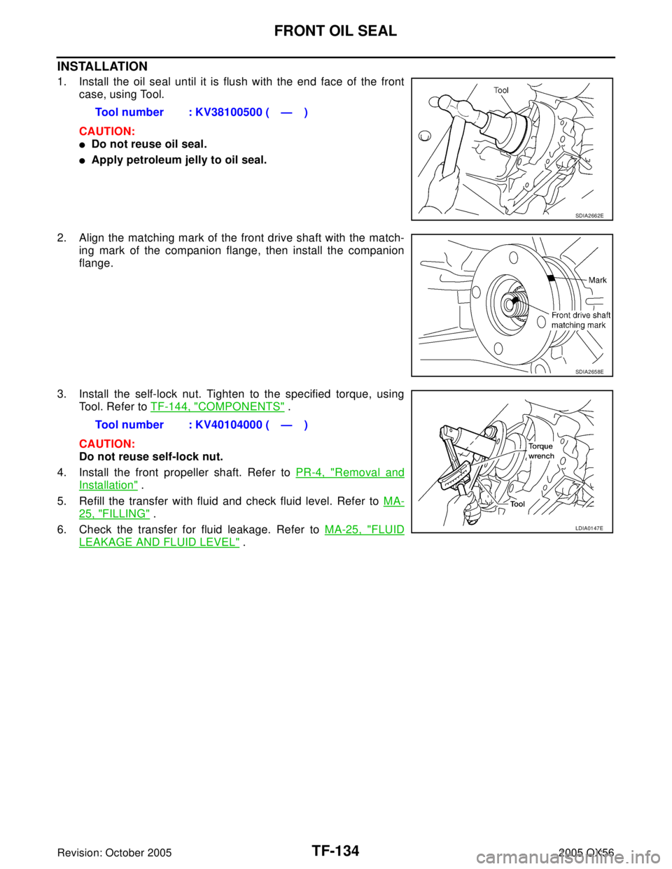
INSTALLATION
1. Install the oil seal until it is flush with the end face of the front
case, using Tool.
CAUTION:
�Do not reuse oil seal.
�Apply petroleum jelly to oil seal.
2. Align the matching mark of the front drive shaft with the match-
ing mark of the companion flange, then install the companion
flange.
3. Install the self-lock nut. Tighten to the specified torque, using
Tool. Refer to TF-144, "
COMPONENTS" .
CAUTION:
Do not reuse self-lock nut.
4. Install the front propeller shaft. Refer to PR-4, "
Removal and
Installation" .
5. Refill the transfer with fluid and check fluid level. Refer to MA-
25, "FILLING" .
6. Check the transfer for fluid leakage. Refer to MA-25, "
FLUID
LEAKAGE AND FLUID LEVEL" . Tool number : KV38100500 ( — )
SDIA2662E
SDIA2658E
Tool number : KV40104000 ( — )
LDIA0147E
Page 3287 of 3419
TF-144
TRANSFER ASSEMBLY
Revision: October 20052005 QX56
Disassembly and AssemblyEDS002H2
COMPONENTS
1. 2-4 sleeve 2. L-H sleeve 3. Snap ring
4. Internal gear 5. Planetary carrier assembly 6. Metal bushing
7. Needle bearing 8. Sun gear 9. Carrier bearing
10. Snap ring 11. Snap ring 12. Mainshaft front bearing
13. Wait detection switch 14. Check plug 15. Check spring
16. Check ball 17. Front case 18. Snap ring
19. Oil seal 20. Shift cross 21. Oil seal
22. Lock pin 23. Shift lever 24. Gasket
25. Drain plug 26. Oil seal 27. Companion flange
28. Self-lock nut 29. Main shaft 30. Needle bearing
31. Front bearing 32. Front drive shaft 33. Rear bearing
34. Spacer 35. Drive chain 36. Clutch drum
37. Snap ring 38. Clutch hub 39. Snap ring
40. Retaining plate 41. Driven plate (10 sheet) 42. Drive plate (10 sheet)
43. Return spring assembly 44. Press flange 45. Thrust needle bearing
46. Snap ring 47. Retaining pin 48. L-H fork
WDIA0194E
Page 3290 of 3419
TRANSFER ASSEMBLY
TF-147
C
E
F
G
H
I
J
K
L
MA
B
TF
Revision: October 20052005 QX56
Front Case
1. Remove the rear case assembly. Refer to TF-146, "Rear Case" .
2. Remove the transfer control device. Refer to TF-138, "
Removal and Installation" .
3. Remove the lock pin nut.
4. Remove the lock pin, using suitable tool.
5. Remove the shift lever.
6. Remove the oil seal from the front case, using suitable tool.
CAUTION:
Do not damage front case or shift cross.
7. Remove the check plug, check spring and check ball.
8. Remove the wait detection switch.
9. Remove the self-lock nut from the companion flange, using Tool.
SDIA2150E
SDIA2166E
WDIA0196E
Tool number : KV40104000 ( — )
SDIA2657E