Page 1 of 4731

ABCDEFGHIJKMLQUICK REFERENCE INDEX AGENERAL INFORMATIONGIGeneral InformationBENGINEEMEngine MechanicalLUEngine Lubrication SystemCOEngine Cooling SystemECEngine Control SystemFLFuel SystemEXExhaust SystemACCAccelerator Control SystemCTRANSMISSION/
TRANSAXLEATAutomatic TransmissionDDRIVELINE/AXLETFTransferPRPropeller ShaftFFDFront Final DriveRFDRear Final DriveFAXFront AxleRAXRear AxleESUSPENSIONFSUFront SuspensionRSURear SuspensionWTRoad Wheels & TiresFBRAKESBRBrake SystemPBParking Brake SystemBRCBrake Control SystemGSTEERINGPSPower Steering SystemHRESTRAINTSSBSeat BeltsSRSSupplemental Restraint System
(SRS)IBODYBLBody, Lock & Security SystemGWGlasses, Window System & Mir-
rorsRFRoofEIExterior & InteriorIPInstrument PanelSESeatJAIR CONDITIONERATCAutomatic Air ConditionerKELECTRICALSCStarting & Charging SystemLTLighting SystemDIDriver Information SystemWWWiper, Washer & HornBCSBody Control SystemLANLAN SystemAVAudio Visual, Navigation & Tele-
phone SystemACSAuto Cruise Control SystemPGPower Supply, Ground & Circuit Ele-
mentsLMAINTENANCEMAMaintenanceMINDEXIDXAlphabetical IndexEdition: August 2004
Revision: July 2005
Page 95 of 4731

AT-12
A/T FLUID
Revision: 2005 July 2005 FX
A/T FLUIDPFP:KLE40
Changing A/T FluidACS002LB
1. Warm up ATF.
2. Stop engine.
3. Loosen the level gauge bolt.
4. Drain ATF from drain plug and refill with new ATF. Always refill same volume with drained ATF.
�To replace the ATF, pour in new ATF at the A/T fluid charging
pipe with the engine idling, at the same time drain the old ATF
from the radiator cooler hose return side.
�When the color of the ATF coming out is almost same as the
color of the new ATF, the replacement is complete. The
amount of new ATF to use should be 30 to 50% of the stipu-
lated amount.
CAUTION:
�Use only Genuine NISSAN Matic J ATF. Do not mix with other ATF.
�Using ATF other than Genuine NISSAN Matic J ATF will cause deterioration in driveability and A/
T durability, and may damage the A/T, which is not covered by the warranty.
�When filling ATF, take care not to scatter heat generating parts such as exhaust.
�Do not reuse drain plug gasket.
5. Run engine at idle speed for 5 minutes.
6. Check A/T fluid level and condition. Refer to AT- 1 3 , "
Checking A/T Fluid" . If ATF is still dirty, repeat step 2.
through 5.
7. Install the removed A/T fluid level gauge into A/T fluid charging pipe.
8. Tighten the level gauge bolt. ATF: Genuine NISSAN Matic J ATF
Fluid capacity: 10.3 (10-7/8 US qt, 9-1/8 lmp qt)
Drain plug: : 34 N·m (3.5 kg-m, 25 ft-lb)
Level gauge bolt: : 5.1 N·m (0.52 kg-m, 45 in-lb)
SCIA4896E
Page 96 of 4731

A/T FLUID AT-13
D E
F
G H
I
J
K L
M A
B
AT
Revision: 2005 July 2005 FX
Checking A/T FluidACS002LC
1. Warm up engine.
2. Check for A/T fluid leakage.
3. Loosen the level gauge bolt.
4. Before driving, A/T fluid level can be checked at A/T fluid tem- peratures of 30 to 50 °C (86 to 122 °F) using “COLD” range on A/
T fluid level gauge as follows.
a. Park vehicle on level surface and set parking brake.
b. Start engine and move selector lever through each gear posi- tion. Leave selector lever in P position.
c. Check A/T fluid level with engine idling.
d. Remove A/T fluid level gauge and wipe clean with lint-free paper.
CAUTION:
When wiping away the A/T fluid level gauge, always use
lint-free paper, not a cloth one.
e. Re-insert A/T fluid level gauge into A/T fluid charging pipe as far as it will go. CAUTION:
To check A/T fluid level, insert the A/T fluid level gauge until the cap contacts the end of the A/T
fluid charging pipe, with the A/T fluid level gauge reversed from the normal attachment conditions.
f. Remove A/T fluid level gauge and note reading. If reading is at low side of range, add ATF to the A/T fluid charging pipe.
CAUTION:
Do not overfill.
5. Drive vehicle for approximately 5 minutes in urban areas.
6. Make the A/T fluid temperature approximately 65 °C (149 °F).
NOTE:
A/T fluid level will be greatly affected by temperature as shown in figure. Therefore, be certain to
perform operation while checking data with CONSULT-II.
a. Connect CONSULT-II to data link connector.
b. Select “MAIN SIGNALS” in “DATA MONITOR” mode for “A/T” with CONSULT-II.
c. Read out the value of “ATF TEMP 1”.
7. Recheck A/T fluid level at A/T fluid temperatures of approximately 65 °C (149 °F) using “HOT” range on A/
T fluid level gauge.
SCIA7120E
SLIA0016E
Page 97 of 4731
AT-14
A/T FLUID
Revision: 2005 July 2005 FX
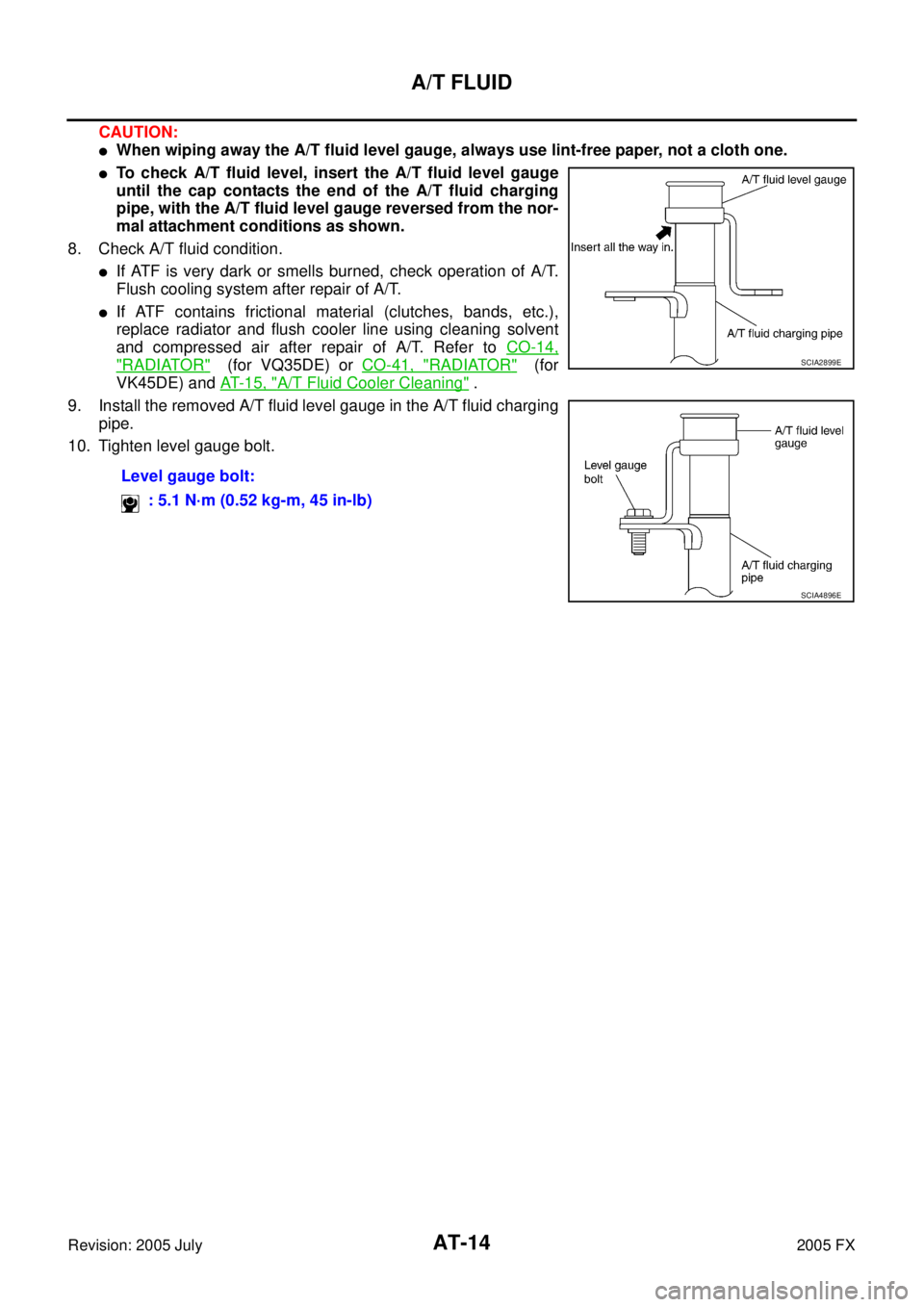
CAUTION:
�When wiping away the A/T fluid level gauge, always use lint-free paper, not a cloth one.
�To check A/T fluid level, insert the A/T fluid level gauge
until the cap contacts the end of the A/T fluid charging
pipe, with the A/T fluid level gauge reversed from the nor-
mal attachment conditions as shown.
8. Check A/T fluid condition.
�If ATF is very dark or smells burned, check operation of A/T.
Flush cooling system after repair of A/T.
�If ATF contains frictional material (clutches, bands, etc.),
replace radiator and flush cooler line using cleaning solvent
and compressed air after repair of A/T. Refer to CO-14,
"RADIATOR" (for VQ35DE) or CO-41, "RADIATOR" (for
VK45DE) and AT- 1 5 , "
A/T Fluid Cooler Cleaning" .
9. Install the removed A/T fluid level gauge in the A/T fluid charging pipe.
10. Tighten level gauge bolt.
Level gauge bolt: : 5.1 N·m (0.52 kg-m, 45 in-lb)
SCIA2899E
SCIA4896E
Page 353 of 4731
ACS002S1
COMPONENTS
REMOVAL
CAUTION:
When removing the transmission assem")
AT-270
TRANSMISSION ASSEMBLY
Revision: 2005 July 2005 FX
TRANSMISSION ASSEMBLYPFP:31020
Removal and Installation (2WD Models)ACS002S1
COMPONENTS
REMOVAL
CAUTION:
When removing the transmission assembly from engine, first remove the crankshaft position sensor
(POS) from the transmission assembly.
Be careful not to damage sensor edge.
1. Disconnect the battery cable from the negative terminal.
2. Remove engine cover.
3. Remove A/T fluid level gauge.
4. Remove engine under cover with power tool.
5. Remove front cross bar. Refer to FSU-8, "
Components"
6. Remove exhaust front tube and center muffler with power tool. Refer to EX-3, "Removal and Installation" .
7. Remove three way catalyst. Refer to EM-26, "
Removal and Installation" .
8. Remove rear propeller shaft. Refer to PR-9, "
Removal and Installation" .
9. Remove control rod. Refer to AT- 2 3 4 , "
Control Rod Removal and Installation" .
1. A/T fluid charging pipe 2. O-ring 3. Engine mounting insulator (rear)
4. Rear engine mounting member 5. Copper washer 6. Fluid cooler tube
7. Bracket 8. Transmission assembly 9. A/T fluid level gauge
SCIA6379E
Page 354 of 4731
 from transmission
assembly.
CAUTION:
�Do not subject it to")
TRANSMISSION ASSEMBLY AT-271
D E
F
G H
I
J
K L
M A
B
AT
Revision: 2005 July 2005 FX
10. Remove crankshaft position sensor (POS) from transmission
assembly.
CAUTION:
�Do not subject it to impact by dropping or hitting it.
�Do not disassemble.
�Do not allow metal filings, etc. to get on the sensor's front
edge magnetic area.
�Do not place in an area affected by magnetism.
11. Remove starter motor. Refer to SC-18, "
VQ35DE ENGINE
MODELS (2WD)" .
12. Remove fluid cooler tube.
13. Remove rear plate cover. Refer to EM-30, "
Removal and Installation (2WD Model)" .
14. Remove rear cover plate. Refer to EM-30, "
Removal and Installation (2WD Model)" .
15. Turn crankshaft, and remove the four tightening bolts for drive plate and torque converter.
CAUTION:
When turning crankshaft, turn it clockwise as viewed from
the front of the engine.
16. Support transmission assembly with a transmission jack. CAUTION:
When setting the transmission jack, be careful not to allow
it to collide against the drain plug.
17. Remove rear engine mounting member with power tool.
18. Remove air breather hose. Refer to AT- 2 6 8 , "
Removal and
Installation" .
19. Disconnect A/T assembly connector.
20. Remove A/T fluid charging pipe from transmission assembly.
21. Plug up openings such as the fluid charging pipe hole, etc.
22. Remove bolts fixing transmission assembly to engine assembly with power tool.
23. Remove transmission assembly from vehicle with a transmis- sion jack.
�Secure torque converter to prevent it from dropping.
�Secure transmission assembly to a transmission jack.
INSPECTION
Installation and Inspection of Torque Converter
�After inserting a torque converter to a transmission, be sure to
check distance “A” to ensure it is within the reference value limit.
SCIA2155E
SCIA2288E
SCIA0499E
Distance “A”: 25.0 mm (0.98 in) or more
SAT017B
Page 356 of 4731
TRANSMISSION ASSEMBLY AT-273
D E
F
G H
I
J
K L
M A
B
AT
Revision: 2005 July 2005 FX
Removal and Installation (AWD Models) ACS0033A
COMPONENTS (FOR VQ35DE)
1. A/T fluid charging pipe 2. O-ring 3. Engine mounting insulator (rear)
4. Rear engine mounting member 5. Copper washer 6. Bracket
7. Fluid cooler tube 8. Bracket 9. Transmission assembly
10. A/T fluid level gauge
SCIA6425E
Page 357 of 4731

REMOVAL
CAUTION:
When removing the transmission assembly from engine, first remove the crankshaft position sensor
(PO")
AT-274
TRANSMISSION ASSEMBLY
Revision: 2005 July 2005 FX
COMPONENTS (FOR VK45DE)
REMOVAL
CAUTION:
When removing the transmission assembly from engine, first remove the crankshaft position sensor
(POS) from the transmission assembly.
Be careful not to damage sensor edge.
1. Disconnect the battery cable from the negative terminal.
2. Remove engine cover.
3. Remove A/T fluid level gauge.
4. Remove engine under cover with power tool.
5. Remove front cross bar. Refer to FSU-8, "
Components" .
6. Remove exhaust front tube and center muffler with power tool. Refer to EX-3, "
Removal and Installation" .
7. Remove three way catalyst. Refer to EM-182, "
Removal and Installation" .
8. Remove front propeller shaft. Refer to PR-5, "
Removal and Installation" .
9. Remove rear propeller shaft. Refer to PR-9, "
Removal and Installation" .
10. Remove control rod. Refer to AT- 2 3 4 , "
Control Rod Removal and Installation" .
1. A/T fluid charging pipe 2. O-ring 3. Engine mounting insulator (rear)
4. Rear engine mounting member 5. Copper washer 6. Bracket
7. Fluid cooler tube 8. Bracket 9. Bracket
10. Bracket 11. Transmission assembly 12. A/T fluid level gauge
SCIA6426E
 ACS0033A
COMPONENTS (FOR VQ35DE)
1. A/T fluid charging pipe 2. O-r")