Page 466 of 4731

LUBRICANT ATC-29
C
D E
F
G H
I
K L
M A
B
AT C
Revision: 2005 July 2005 FX
LUBRICANT ADJUSTING PROCEDURE FOR COMPRESSOR REPLACEMENT
1. Before connecting recovery/recycling recharging equipment to vehicle, check recovery/recycling recharg-
ing equipment gauges. No refrigerant pressure should be displayed. If NG, recover refrigerant from equip-
ment lines.
2. Connect recovery/recycling recharging equipment to vehicle. Confirm refrigerant purity in supply tank using recovery/recycling recharging equipment and refrigerant identifier. If NG, refer to AT C - 7 , "
CONTAM-
INATED REFRIGERANT" .
3. Confirm refrigerant purity in vehicle A/C system using recovery/recycling recharging equipment and refrig- erant identifier. If NG, refer to AT C - 7 , "
CONTAMINATED REFRIGERANT" .
4. Discharge refrigerant into the refrigerant recovery/recycling equipment. Measure lubricant discharged into the recovery/recycling equipment.
5. Drain the lubricant from the old (removed) compressor into a graduated container and recover the amount of lubricant drained.
6. Drain the lubricant from the new compressor into a separate, clean container.
7. Measure an amount of new lubricant installed equal to amount drained from old compressor. Add this lubricant to new compressor through the suction port opening.
8. Measure an amount of new lubricant equal to the amount recovered during discharging. Add this lubricant to new compressor through the suction port opening.
9. If the liquid tank also needs to be replaced, add another 5 m (0.2 US fl oz., 0.2 Imp fl oz.) of lubricant at this time.
Do not add this 5 m (0.2 US fl oz., 0.2 Imp fl oz.) of lubricant if only replacing the compressor.
RJIA3578E
Page 557 of 4731

ATC-120
INTAKE SENSOR
Revision: 2005 July 2005 FX
INTAKE SENSORPFP:27723
Removal and InstallationAJS0015D
REMOVAL
1. Remove low-pressure pipe 2 and high-pressure pipe 3. Refer to ATC-152, "Removal and Installation of
Low-Pressure Pipe 2 and High-Pressure Pipe 3" .
CAUTION:
Cap or wrap the joint of the pipe with suitable material such as vinyl tape to avoid the entry of air.
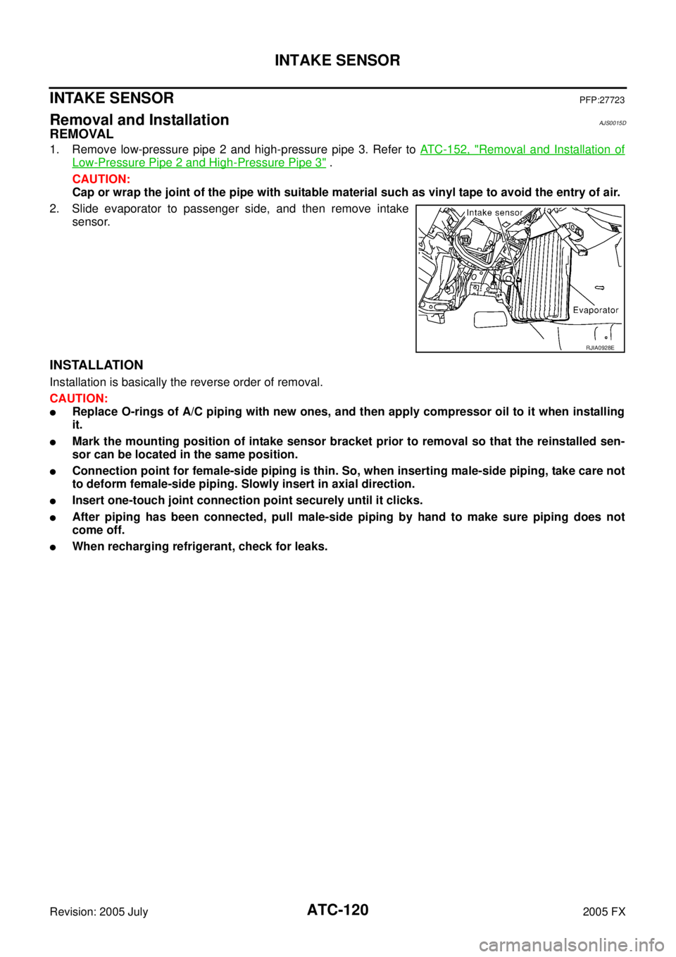
2. Slide evaporator to passenger side, and then remove intake sensor.
INSTALLATION
Installation is basically the reverse order of removal.
CAUTION:
�Replace O-rings of A/C piping with new ones, and then apply compressor oil to it when installing
it.
�Mark the mounting position of intake sensor bracket prior to removal so that the reinstalled sen-
sor can be located in the same position.
�Connection point for female-side piping is thin. So, when inserting male-side piping, take care not
to deform female-side piping. Slowly insert in axial direction.
�Insert one-touch joint connection point securely until it clicks.
�After piping has been connected, pull male-side piping by hand to make sure piping does not
come off.
�When recharging refrigerant, check for leaks.
RJIA0928E
Page 565 of 4731
ATC-128
HEATER & COOLING UNIT ASSEMBLY
Revision: 2005 July 2005 FX
�When recharging refrigerant, check for leaks.
NOTE:
�When filling radiator with coolant, refer to CO-11, "Changing Engine Coolant" (VQ35DE) or CO-37,
"Changing Engine Coolant" (VK45DE).
�Recharge the refrigerant.
Heater & cooling unit mounting bolt
Tightening torque : 6.8 N·m (0.69 kg-m, 60 in-lb)
Steering member mounting nut and bolt
Tightening torque : 12 N·m (1.2 kg-m, 9 fl-lb)
Page 575 of 4731
ATC-138
REFRIGERANT LINES
Revision: 2005 July 2005 FX
REFRIGERANT LINESPFP:92600
HFC-134a (R-134a) Service ProcedureAJS0015P
SETTING OF SERVICE TOOLS AND EQUIPMENT
Discharging Refrigerant
WARNING:
Avoid breathing A/C refrigerant and lubricant vapor or mist. Exposure may irritate eyes, nose and
throat. Remove HFC-134a (R-134a) from A/C system using certified service equipment meeting
requirements of SAE J-2210 [HFC-134a (R-134a) recycling equipment] or J-2209 [HFC-134a (R-134a)
recovery equipment]. If accidental system discharge occurs, ventilate work area before resuming ser-
vice. Additional health and safety information may be obtained from refrigerant and lubricant manu-
facturers.
Evacuating System and Charging Refrigerant
WJIA0614E
WJIA0615E
Page 580 of 4731
REFRIGERANT LINES ATC-143
C
D E
F
G H
I
K L
M A
B
AT C
Revision: 2005 July 2005 FX
9. Disconnect compressor (ECV) connector.
10. Remove mounting bolts from compressor, using power tools.
11. Remove compressor downward of the vehicle.
INSTALLATION
Installation is basically the reverse order of removal.
CAUTION:
�Replace O-rings of low-pressure flexible hose, high-pressure pipe and high-pressure flexible hose
with new ones, and then apply compressor oil to it when installing it.
�When recharging refrigerant, check for leaks.
RJIA2061E
RJIA2060E
Page 586 of 4731

REFRIGERANT LINES ATC-149
C
D E
F
G H
I
K L
M A
B
AT C
Revision: 2005 July 2005 FX
INSTALLATION
Installation is basically the reverse order of removal.
CAUTION:
�Replace O-rings of A/C piping with new ones, and then apply compressor oil to it when installing
it.
�Connection point for female-side piping is thin. So, when inserting male-side piping, take care not
to deform female-side piping. Slowly insert in axial direction.
�Insert one-touch joint connection point securely until it clicks.
�After piping has been connected, pull male-side piping by hand to make sure piping does not
come off.
�When recharging refrigerant, check for leaks.
Removal and Installation of High-Pressure Flexible HoseAJS0015U
REMOVAL
1. Use a refrigerant collecting equipment (for HFC-134a) to discharge the refrigerant.
2. Remove air cleaner case and air duct. Refer to EM-17, "
AIR CLEANER AND AIR DUCT" (VQ35DE) or
EM-176, "
AIR CLEANER AND AIR DUCT" (VK45DE).
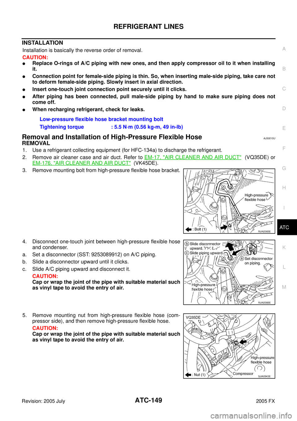
3. Remove mounting bolt from high-pressure flexible hose bracket.
4. Disconnect one-touch joint between high-pressure flexible hose and condenser.
a. Set a disconnector (SST: 9253089912) on A/C piping.
b. Slide a disconnector upward until it clicks.
c. Slide A/C piping upward and disconnect it. CAUTION:
Cap or wrap the joint of the pipe with suitable material such
as vinyl tape to avoid the entry of air.
5. Remove mounting nut from high-pressure flexible hose (com- pressor side), and then remove high-pressure flexible hose.
CAUTION:
Cap or wrap the joint of the pipe with suitable material such
as vinyl tape to avoid the entry of air. Low-pressure flexible hose bracket mounting bolt
Tightening torque : 5.5 N·m (0.56 kg-m, 49 in-lb)
RJIA2065E
RJIA2066E
SJIA0943E
Page 587 of 4731

ATC-150
REFRIGERANT LINES
Revision: 2005 July 2005 FX
INSTALLATION
Installation is basically the reverse order of removal.
CAUTION:
�Replace O-rings of high-pressure flexible hose with new ones, and then apply compressor oil to it
when installing it.
�Connection point for female-side piping is thin. So, when inserting male-side piping, take care not
to deform female-side piping. Slowly insert in axial direction.
�Insert one-touch joint connection point securely until it clicks.
�After piping has been connected, pull male-side piping by hand to make sure piping does not
come off.
�When recharging refrigerant, check for leaks.
Removal and Installation of Low-Pressure Pipe 1 (Engine Compartment)AJS0015V
REMOVAL
1. Use a refrigerant collecting equipment (for HFC-134a) to discharge the refrigerant.
2. Remove cowl top cover. Refer to EI-23, "
COWL TOP" .
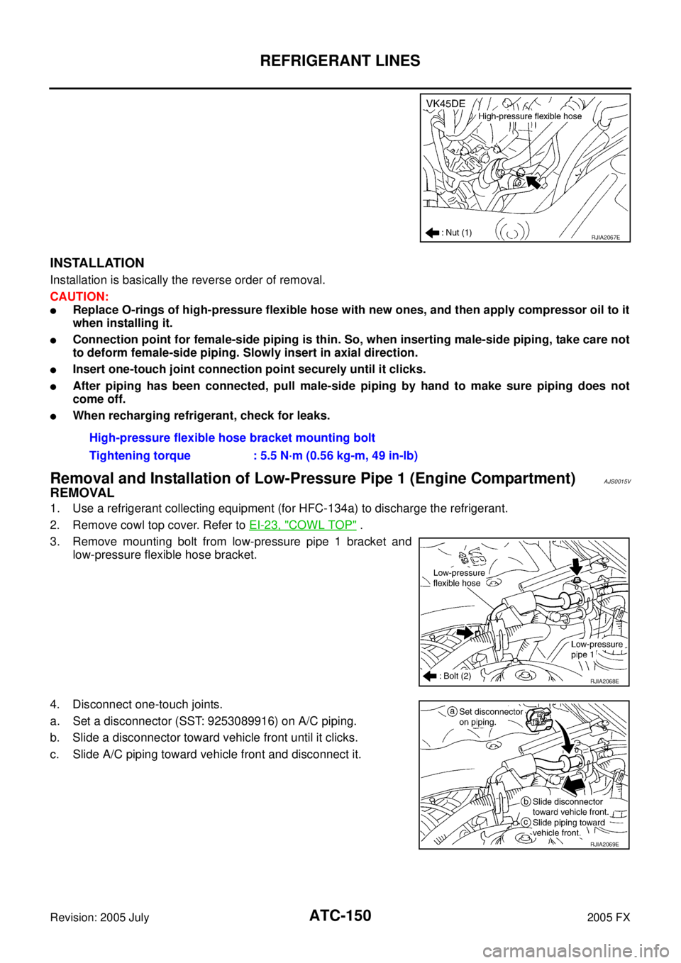
3. Remove mounting bolt from low-pressure pipe 1 bracket and low-pressure flexible hose bracket.
4. Disconnect one-touch joints.
a. Set a disconnector (SST: 9253089916) on A/C piping.
b. Slide a disconnector toward vehicle front until it clicks.
c. Slide A/C piping toward vehicle front and disconnect it.
RJIA2067E
High-pressure flexible hose bracket mounting bolt
Tightening torque : 5.5 N·m (0.56 kg-m, 49 in-lb)
RJIA2068E
RJIA2069E
Page 588 of 4731

REFRIGERANT LINES ATC-151
C
D E
F
G H
I
K L
M A
B
AT C
Revision: 2005 July 2005 FX
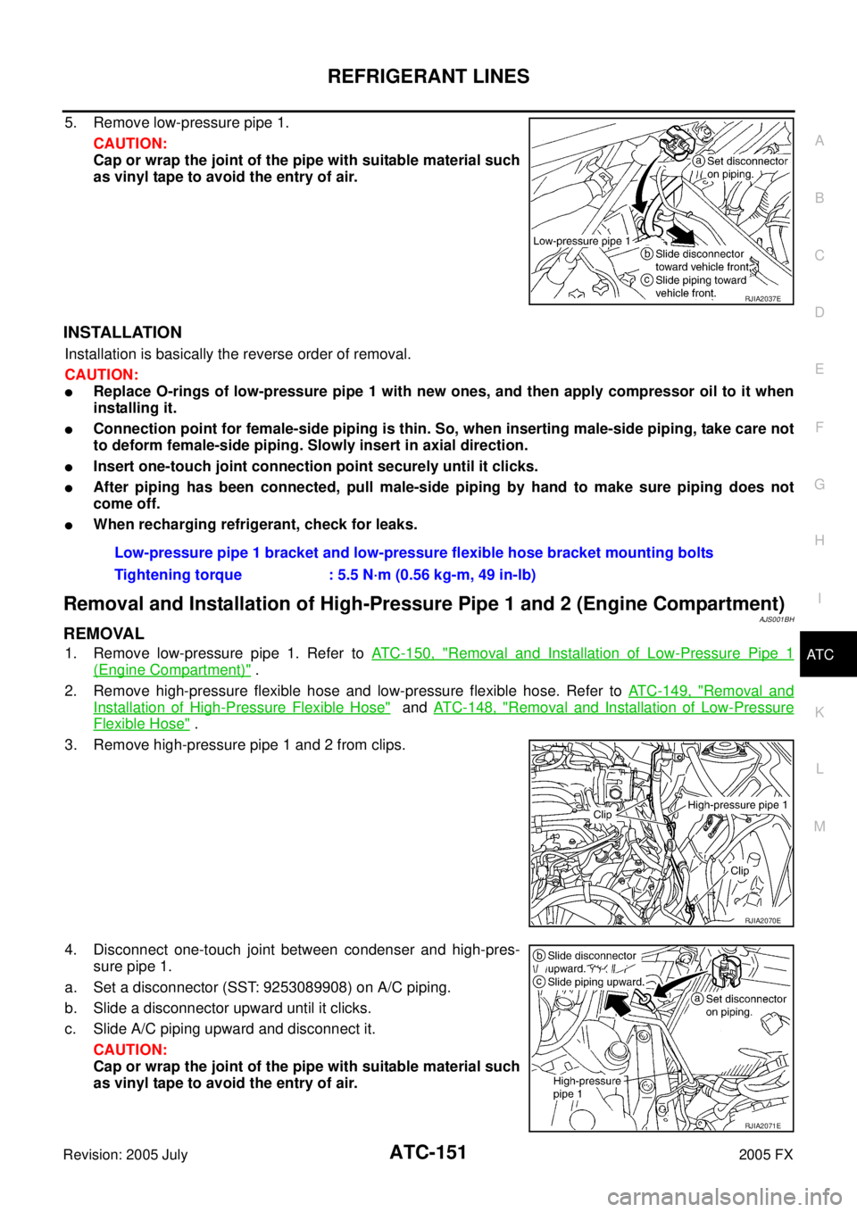
5. Remove low-pressure pipe 1.
CAUTION:
Cap or wrap the joint of the pipe with suitable material such
as vinyl tape to avoid the entry of air.
INSTALLATION
Installation is basically the reverse order of removal.
CAUTION:
�Replace O-rings of low-pressure pipe 1 with new ones, and then apply compressor oil to it when
installing it.
�Connection point for female-side piping is thin. So, when inserting male-side piping, take care not
to deform female-side piping. Slowly insert in axial direction.
�Insert one-touch joint connection point securely until it clicks.
�After piping has been connected, pull male-side piping by hand to make sure piping does not
come off.
�When recharging refrigerant, check for leaks.
Removal and Installation of High-Pressure Pipe 1 and 2 (Engine Compartment)AJS001BH
REMOVAL
1. Remove low-pressure pipe 1. Refer to ATC-150, "Removal and Installation of Low-Pressure Pipe 1
(Engine Compartment)" .
2. Remove high-pressure flexible hose and low-pressure flexible hose. Refer to ATC-149, "
Removal and
Installation of High-Pressure Flexible Hose" and ATC-148, "Removal and Installation of Low-Pressure
Flexible Hose" .
3. Remove high-pressure pipe 1 and 2 from clips.
4. Disconnect one-touch joint between condenser and high-pres- sure pipe 1.
a. Set a disconnector (SST: 9253089908) on A/C piping.
b. Slide a disconnector upward until it clicks.
c. Slide A/C piping upward and disconnect it.
CAUTION:
Cap or wrap the joint of the pipe with suitable material such
as vinyl tape to avoid the entry of air.
RJIA2037E
Low-pressure pipe 1 bracket and low-pressure flexible hose bracket mounting bolts
Tightening torque : 5.5 N·m (0.56 kg-m, 49 in-lb)
RJIA2070E
RJIA2071E