Page 4679 of 4731
TF-46
TRANSFER ASSEMBLY
Revision: 2005 July 2005 FX
DISASSEMBLY
Front Case and Rear Case
1. Remove drain plug and filler plug.
2. Remove mainshaft oil seal from front case, using a flat-bladed screwdriver.
CAUTION:
Be careful not to damage the front case and mainshaft.
3. Remove front oil seal from front case, using a flat-bladed screw- driver.
CAUTION:
Be careful not to damage the front case and front drive
shaft.
4. Remove self-lock nut.
5. Put a matching mark on the end of mainshaft. The mark should be in line with the mark on the companion flange.
CAUTION:
For matching mark, use paint. Do not damage mainshaft.
6. Remove companion flange, using a puller. CAUTION:
Be careful not to damage the companion flange.
PDIA0253E
PDIA0255E
SDIA2378E
PDIA0258E
Page 4690 of 4731

TRANSFER ASSEMBLY TF-57
C E F
G H
I
J
K L
M A
B
TF
Revision: 2005 July 2005 FX
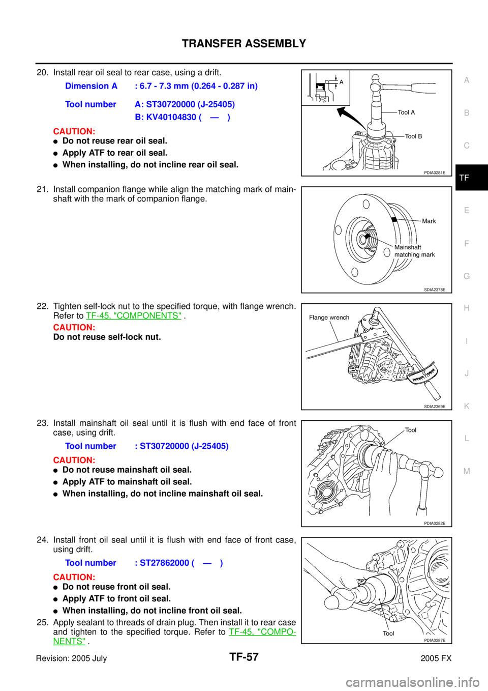
20. Install rear oil seal to rear case, using a drift.
CAUTION:
�Do not reuse rear oil seal.
�Apply ATF to rear oil seal.
�When installing, do not incline rear oil seal.
21. Install companion flange while align the matching mark of main- shaft with the mark of companion flange.
22. Tighten self-lock nut to the specified torque, with flange wrench. Refer to TF-45, "
COMPONENTS" .
CAUTION:
Do not reuse self-lock nut.
23. Install mainshaft oil seal until it is flush with end face of front case, using drift.
CAUTION:
�Do not reuse mainshaft oil seal.
�Apply ATF to mainshaft oil seal.
�When installing, do not incline mainshaft oil seal.
24. Install front oil seal until it is flush with end face of front case, using drift.
CAUTION:
�Do not reuse front oil seal.
�Apply ATF to front oil seal.
�When installing, do not incline front oil seal.
25. Apply sealant to threads of drain plug. Then install it to rear case and tighten to the specified torque. Refer to TF-45, "
COMPO-
NENTS" .
Dimension A : 6.7 - 7.3 mm (0.264 - 0.287 in)
Tool number A: ST30720000 (J-25405) B: KV40104830 ( — )
PDIA0281E
SDIA2378E
SDIA2369E
Tool number : ST30720000 (J-25405)
PDIA0282E
Tool number : ST27862000 ( — )
PDIA0287E
Page 4698 of 4731

ROAD WHEEL TIRE ASSEMBLY WT-5
C
D
F
G H
I
J
K L
M A
B
WT
Revision: 2005 July 2005 FX
ROAD WHEEL TIRE ASSEMBLYPFP:40300
Balancing Wheels (Bonding Weight Type)AES000JM
REMOVAL
1. Remove inner and outer balance weights from the road wheel.
CAUTION:
Be careful not to scratch the road wheel during removal.
2. Using releasing agent, remove double-faced adhesive tape from the road wheel. CAUTION:
�Be careful not to scratch the road wheel during removal.
�After removing double-faced adhesive tape, wipe clean traces of releasing agent from the road
wheel.
WHEEL BALANCE ADJUSTMENT
�If a tire balance machine has adhesion balance weight mode settings and drive-in weight mode setting,
select and adjust a drive-in weight mode suitable for road wheels.
1. Set road wheel on wheel balancer using the center hole as a guide. Start the tire balance machine.
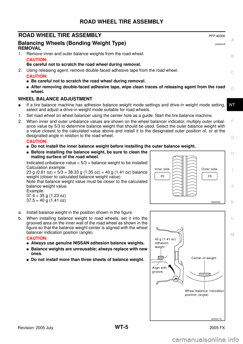
2. When inner and outer unbalance values are shown on the wheel balancer indicator, multiply outer unbal- ance value by 5/3 to determine balance weight that should be used. Select the outer balance weight with
a value closest to the calculated value above and install it to the designated outer position of, or at the
designated angle in relation to the road wheel.
CAUTION:
�Do not install the inner balance weight before installing the outer balance weight.
�Before installing the balance weight, be sure to clean the
mating surface of the road wheel.
Indicated unbalance value × 5/3 = balance weight to be installed
Calculation example:
23 g (0.81 oz) × 5/3 = 38.33 g (1.35 oz) = 40 g (1.41 oz) balance
weight (closer to calculated balance weight value)
Note that balance weight value must be closer to the calculated
balance weight value.
Example:
37.4 = 35 g (1.23 oz)
37.5 = 40 g (1.41 oz)
a. Install balance weight in the position shown in the figure.
b. When installing balance weight to road wheels, set it into the grooved area on the inner wall of the road wheel as shown in the
figure so that the balance weight center is aligned with the wheel
balancer indication position (angle).
CAUTION:
�Always use genuine NISSAN adhesion balance weights.
�Balance weights are unreusable; always replace with new
ones.
�Do not install more than three sheets of balance weight.
SMA054D
SEIA0271E