Page 4391 of 4731
RFD-22
REAR FINAL DRIVE ASSEMBLY
Revision: 2005 July 2005 FX
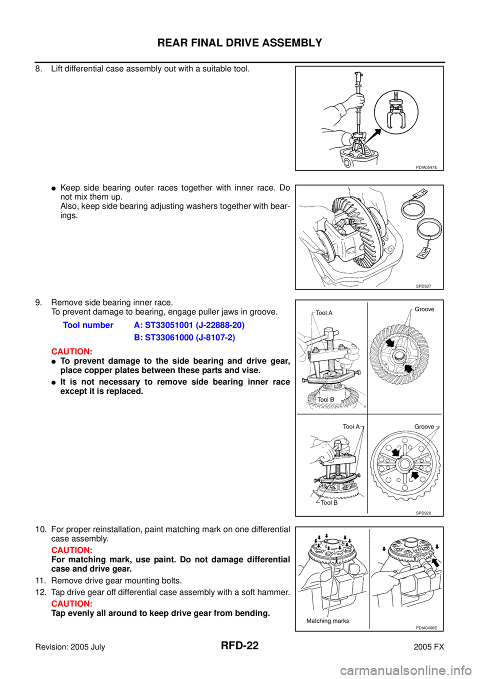
8. Lift differential case assembly out with a suitable tool.
�Keep side bearing outer races together with inner race. Do
not mix them up.
Also, keep side bearing adjusting washers together with bear-
ings.
9. Remove side bearing inner race. To prevent damage to bearing, engage puller jaws in groove.
CAUTION:
�To prevent damage to the side bearing and drive gear,
place copper plates between these parts and vise.
�It is not necessary to remove side bearing inner race
except it is replaced.
10. For proper reinstallation, paint matching mark on one differential case assembly.
CAUTION:
For matching mark, use paint. Do not damage differential
case and drive gear.
11. Remove drive gear mounting bolts.
12. Tap drive gear off differential case assembly with a soft hammer. CAUTION:
Tap evenly all around to keep drive gear from bending.
PDIA0547E
SPD527
Tool number A: ST33051001 (J-22888-20)
B: ST33061000 (J-8107-2)
SPD920
PDIA0496E
Page 4393 of 4731
RFD-24
REAR FINAL DRIVE ASSEMBLY
Revision: 2005 July 2005 FX
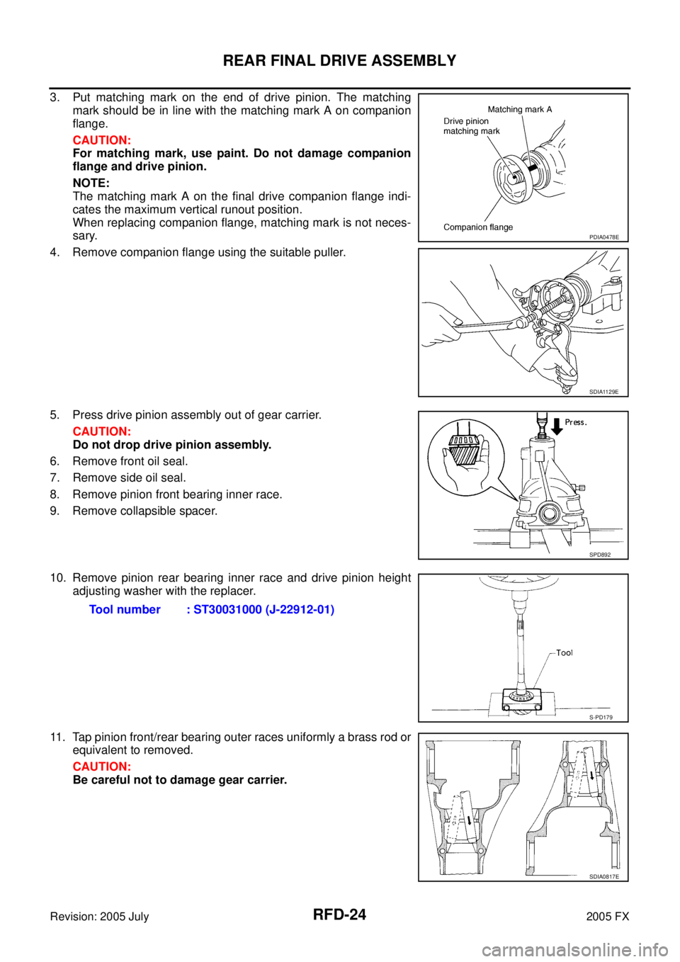
3. Put matching mark on the end of drive pinion. The matching
mark should be in line with the matching mark A on companion
flange.
CAUTION:
For matching mark, use paint. Do not damage companion
flange and drive pinion.
NOTE:
The matching mark A on the final drive companion flange indi-
cates the maximum vertical runout position.
When replacing companion flange, matching mark is not neces-
sary.
4. Remove companion flange using the suitable puller.
5. Press drive pinion assembly out of gear carrier. CAUTION:
Do not drop drive pinion assembly.
6. Remove front oil seal.
7. Remove side oil seal.
8. Remove pinion front bearing inner race.
9. Remove collapsible spacer.
10. Remove pinion rear bearing inner race and drive pinion height adjusting washer with the replacer.
11. Tap pinion front/rear bearing outer races uniformly a brass rod or equivalent to removed.
CAUTION:
Be careful not to damage gear carrier.
PDIA0478E
SDIA1129E
SPD892
Tool number : ST30031000 (J-22912-01)
S-PD179
SDIA0817E
Page 4394 of 4731
REAR FINAL DRIVE ASSEMBLY RFD-25
C E F
G H
I
J
K L
M A
B
RFD
Revision: 2005 July 2005 FX
INSPECTION AFTER DISASSEMBLY
Clean up the disassembled parts. Then, inspect if the parts are worn or damaged. If so, follow the measures
below.
ADJUSTMENT AND SELECTION OF ADJUSTING WASHERS
Differential Side Gear Clearance
�Assemble the differential parts if they are disassembled. Refer to RFD-32, "Differential Assembly" .
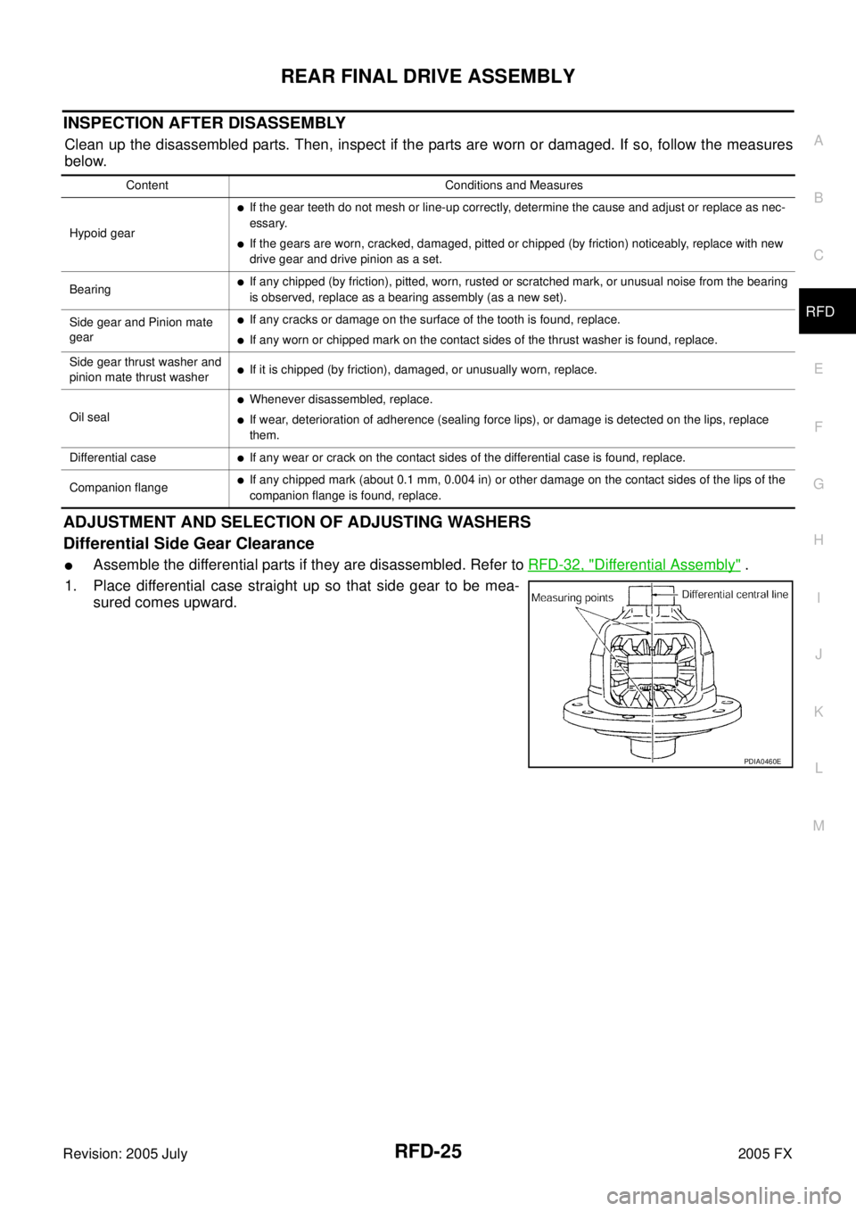
1. Place differential case straight up so that side gear to be mea- sured comes upward.
Content Conditions and Measures
Hypoid gear
�If the gear teeth do not mesh or line-up correctly, determine the cause and adjust or replace as nec-
essary.
�If the gears are worn, cracked, damaged, pitted or chipped (by friction) noticeably, replace with new
drive gear and drive pinion as a set.
Bearing
�If any chipped (by friction), pitted, worn, rusted or scratched mark, or unusual noise from the bearing
is observed, replace as a bearing assembly (as a new set).
Side gear and Pinion mate
gear
�If any cracks or damage on the surface of the tooth is found, replace.
�If any worn or chipped mark on the contact sides of the thrust washer is found, replace.
Side gear thrust washer and
pinion mate thrust washer
�If it is chipped (by friction), damaged, or unusually worn, replace.
Oil seal
�Whenever disassembled, replace.
�If wear, deterioration of adherence (sealing force lips), or damage is detected on the lips, replace
them.
Differential case
�If any wear or crack on the contact sides of the differential case is found, replace.
Companion flange
�If any chipped mark (about 0.1 mm, 0.004 in) or other damage on the contact sides of the lips of the
companion flange is found, replace.
PDIA0460E
Page 4398 of 4731
REAR FINAL DRIVE ASSEMBLY RFD-29
C E F
G H
I
J
K L
M A
B
RFD
Revision: 2005 July 2005 FX
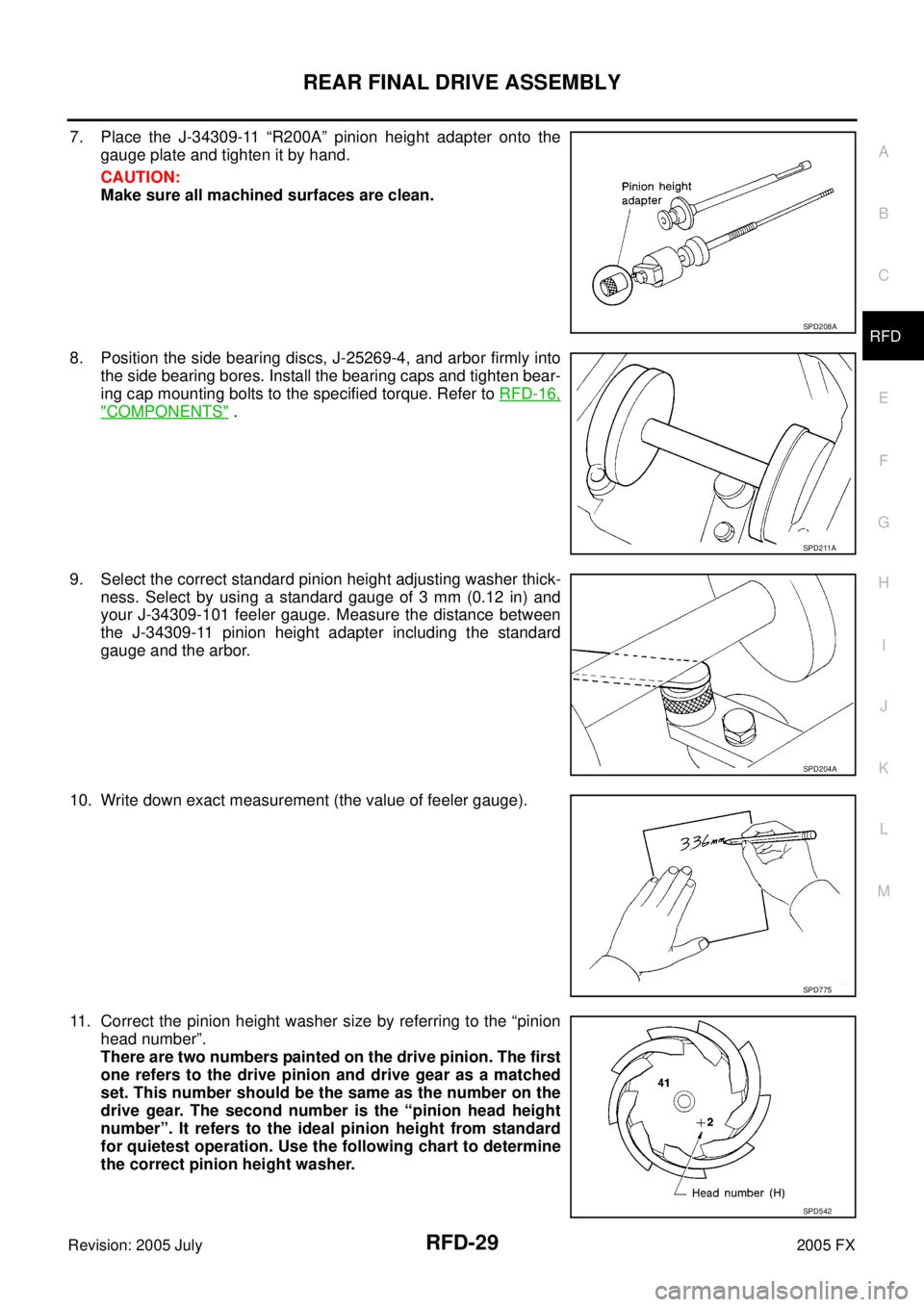
7. Place the J-34309-11 “R200A” pinion height adapter onto the
gauge plate and tighten it by hand.
CAUTION:
Make sure all machined surfaces are clean.
8. Position the side bearing discs, J-25269-4, and arbor firmly into the side bearing bores. Install the bearing caps and tighten bear-
ing cap mounting bolts to the specified torque. Refer to RFD-16,
"COMPONENTS" .
9. Select the correct standard pinion height adjusting washer thick- ness. Select by using a standard gauge of 3 mm (0.12 in) and
your J-34309-101 feeler gauge. Measure the distance between
the J-34309-11 pinion height adapter including the standard
gauge and the arbor.
10. Write down exact measurement (the value of feeler gauge).
11. Correct the pinion height washer size by referring to the “pinion head number”.
There are two numbers painted on the drive pinion. The first
one refers to the drive pinion and drive gear as a matched
set. This number should be the same as the number on the
drive gear. The second number is the “pinion head height
number”. It refers to the ideal pinion height from standard
for quietest operation. Use the following chart to determine
the correct pinion height washer.
SPD208A
SPD211A
SPD204A
SPD775
SPD542
Page 4400 of 4731
REAR FINAL DRIVE ASSEMBLY RFD-31
C E F
G H
I
J
K L
M A
B
RFD
Revision: 2005 July 2005 FX
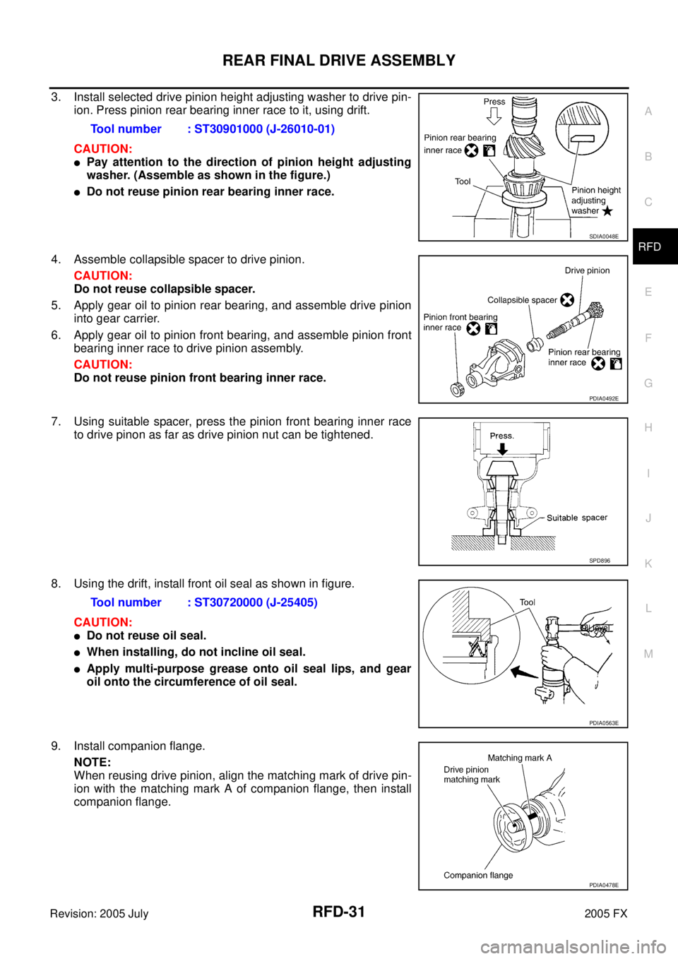
3. Install selected drive pinion height adjusting washer to drive pin-
ion. Press pinion rear bearing inner race to it, using drift.
CAUTION:
�Pay attention to the direction of pinion height adjusting
washer. (Assemble as shown in the figure.)
�Do not reuse pinion rear bearing inner race.
4. Assemble collapsible spacer to drive pinion. CAUTION:
Do not reuse collapsible spacer.
5. Apply gear oil to pinion rear bearing, and assemble drive pinion into gear carrier.
6. Apply gear oil to pinion front bearing, and assemble pinion front bearing inner race to drive pinion assembly.
CAUTION:
Do not reuse pinion front bearing inner race.
7. Using suitable spacer, press the pinion front bearing inner race to drive pinon as far as drive pinion nut can be tightened.
8. Using the drift, install front oil seal as shown in figure. CAUTION:
�Do not reuse oil seal.
�When installing, do not incline oil seal.
�Apply multi-purpose grease onto oil seal lips, and gear
oil onto the circumference of oil seal.
9. Install companion flange. NOTE:
When reusing drive pinion, align the matching mark of drive pin-
ion with the matching mark A of companion flange, then install
companion flange. Tool number : ST30901000 (J-26010-01)
SDIA0048E
PDIA0492E
SPD896
Tool number : ST30720000 (J-25405)
PDIA0563E
PDIA0478E
Page 4402 of 4731
REAR FINAL DRIVE ASSEMBLY RFD-33
C E F
G H
I
J
K L
M A
B
RFD
Revision: 2005 July 2005 FX
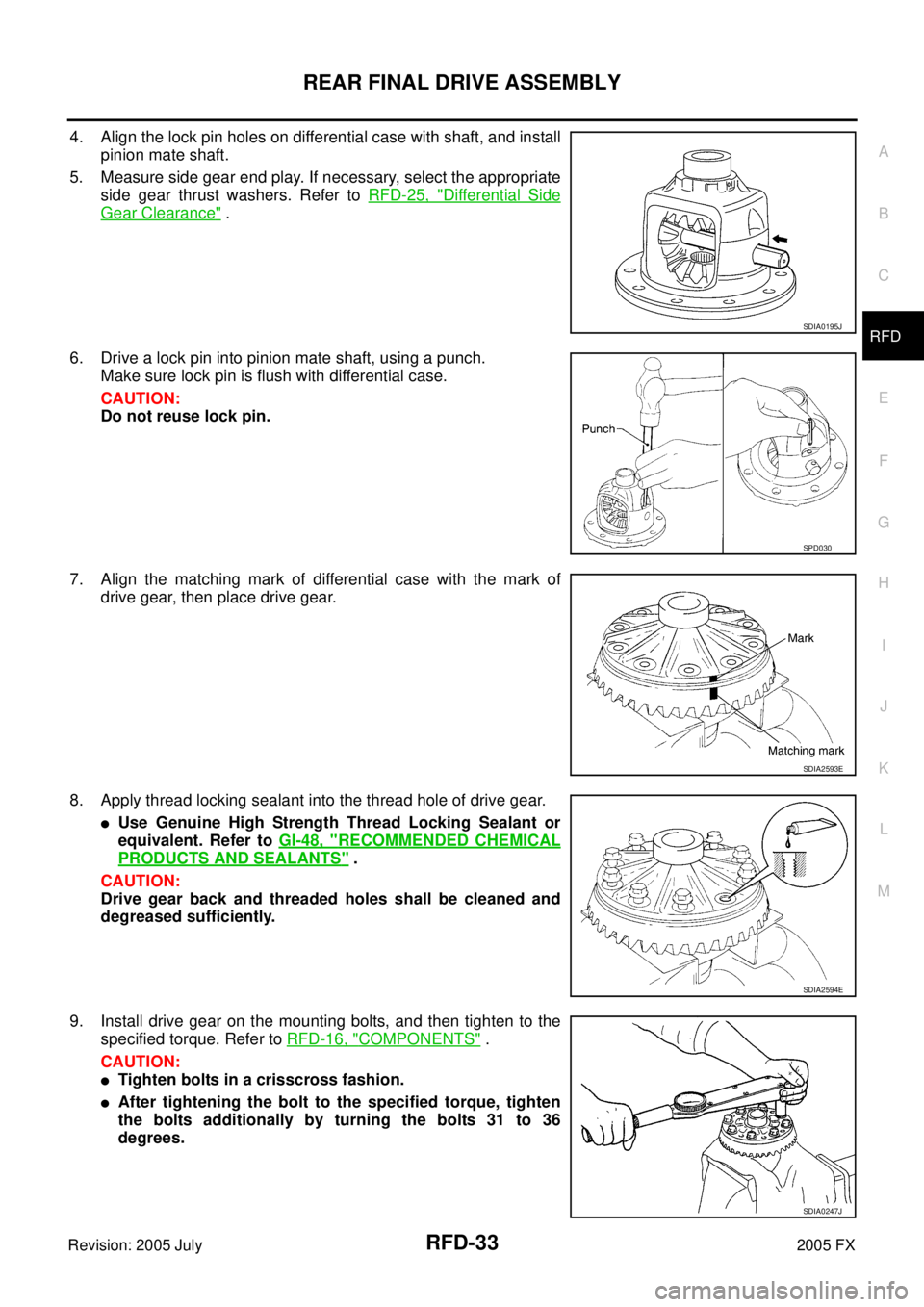
4. Align the lock pin holes on differential case with shaft, and install
pinion mate shaft.
5. Measure side gear end play. If necessary, select the appropriate side gear thrust washers. Refer to RFD-25, "
Differential Side
Gear Clearance" .
6. Drive a lock pin into pinion mate shaft, using a punch. Make sure lock pin is flush with differential case.
CAUTION:
Do not reuse lock pin.
7. Align the matching mark of differential case with the mark of drive gear, then place drive gear.
8. Apply thread locking sealant into the thread hole of drive gear.
�Use Genuine High Strength Thread Locking Sealant or
equivalent. Refer to GI-48, "
RECOMMENDED CHEMICAL
PRODUCTS AND SEALANTS" .
CAUTION:
Drive gear back and threaded holes shall be cleaned and
degreased sufficiently.
9. Install drive gear on the mounting bolts, and then tighten to the specified torque. Refer to RFD-16, "
COMPONENTS" .
CAUTION:
�Tighten bolts in a crisscross fashion.
�After tightening the bolt to the specified torque, tighten
the bolts additionally by turning the bolts 31 to 36
degrees.
SDIA0195J
SPD030
SDIA2593E
SDIA2594E
SDIA0247J
Page 4403 of 4731
RFD-34
REAR FINAL DRIVE ASSEMBLY
Revision: 2005 July 2005 FX
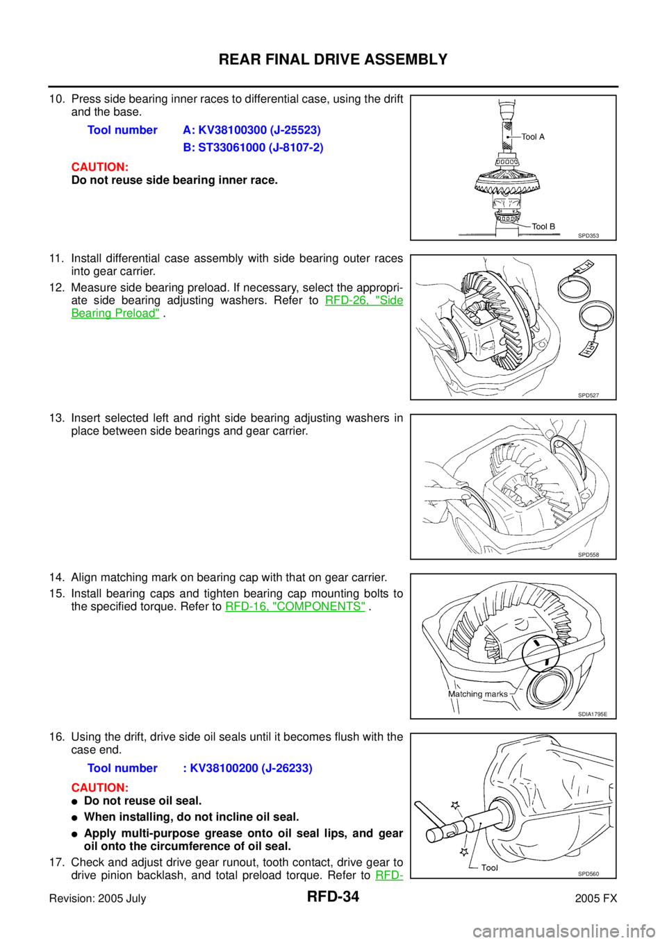
10. Press side bearing inner races to differential case, using the drift
and the base.
CAUTION:
Do not reuse side bearing inner race.
11. Install differential case assembly with side bearing outer races into gear carrier.
12. Measure side bearing preload. If necessary, select the appropri- ate side bearing adjusting washers. Refer to RFD-26, "
Side
Bearing Preload" .
13. Insert selected left and right side bearing adjusting washers in place between side bearings and gear carrier.
14. Align matching mark on bearing cap with that on gear carrier.
15. Install bearing caps and tighten bearing cap mounting bolts to the specified torque. Refer to RFD-16, "
COMPONENTS" .
16. Using the drift, drive side oil seals until it becomes flush with the case end.
CAUTION:
�Do not reuse oil seal.
�When installing, do not incline oil seal.
�Apply multi-purpose grease onto oil seal lips, and gear
oil onto the circumference of oil seal.
17. Check and adjust drive gear runout, tooth contact, drive gear to drive pinion backlash, and total preload torque. Refer to RFD-
Tool number A: KV38100300 (J-25523)
B: ST33061000 (J-8107-2)
SPD353
SPD527
SPD558
SDIA1795E
Tool number : KV38100200 (J-26233)
SPD560
Page 4422 of 4731
REAR LOWER LINK & COIL SPRING RSU-15
C
D
F
G H
I
J
K L
M A
B
RSU
Revision: 2005 July 2005 FX
REAR LOWER LINK & COIL SPRINGPFP:551B0
Removal and InstallationAES000MS
REMOVAL
1. Remove tire with power tool.
2. Set jack under rear lower link.
3. Loosen fixing bolt and nut of rear lower link in side of suspension member, and then remove fixing bolt and nut in side of axle with power tool.
4. Slowly lower jack, then remove upper seat, coil spring and rubber sheet from rear lower link.
5. Remove fixing bolt and nut in side of rear suspension member to remove rear lower link with power tool.
INSPECTION AFTER REMOVAL
Check rear lower link, bushing and coil spring for deformation, cracks, and damage. Replace rear lower link
and coil spring if necessary.
INSTALLATION
�Refer to RSU-7, "Components" for tightening torque. Install in the reverse order of removal.
NOTE:
Refer to component parts location and do not reuse non-reusable parts.
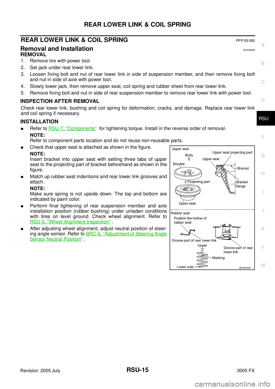
�Check that upper seat is attached as shown in the figure.
NOTE:
Insert bracket into upper seat with setting three tabs of upper
seat to the projecting part of bracket beforehand as shown in the
figure.
�Match up rubber seat indentions and rear lower link grooves and
attach.
NOTE:
Make sure spring is not upside down. The top and bottom are
indicated by paint color.
�Perform final tightening of rear suspension member and axle
installation position (rubber bushing) under unladen conditions
with tires on level ground. Check wheel alignment. Refer to
RSU-5, "
Wheel Alignment Inspection" .
�After adjusting wheel alignment, adjust neutral position of steer-
ing angle sensor. Refer to BRC-6, "
Adjustment of Steering Angle
Sensor Neutral Position" .
SEIA0333E